56
Final Report: Sooner/Exiss Trailers Jig Design May 4, 2013 Tanisha Hamm Kevin Roehm Kaden Wanger Prepared for: Sooner/Exiss Trailer

Final Report: Sooner/Exiss Trailers Jig Design
May 4, 2013
Tanisha Hamm
Kevin Roehm
Kaden Wanger
Prepared for: Sooner/Exiss Trailer

Spring Report
i
Contents
Customer Requirements & Quantitative Specifications ................................................................. 1
Statement of Work .......................................................................................................................... 1
Background ................................................................................................................................. 1
Current Setup............................................................................................................................... 2
Scope of Work ............................................................................................................................. 2
Physical Location ........................................................................................................................ 3
Period of Performance ................................................................................................................. 3
Delivery Requirements ................................................................................................................ 3
Detailed Work ............................................................................................................................. 3
Task List ...................................................................................................................................... 4
Work Breakdown ........................................................................................................................ 5
Payment Schedule ....................................................................................................................... 6
Acceptance Criteria ..................................................................................................................... 6
Special Requirements .................................................................................................................. 6
Technical Analysis .......................................................................................................................... 7
Patent Searches ............................................................................................................................ 9
Engineering Calculations ................................................................................................................ 9
Weight ......................................................................................................................................... 9
Deflection .................................................................................................................................. 11
Torsion ...................................................................................................................................... 12
Tipping ...................................................................................................................................... 13
Buckling .................................................................................................................................... 14
New Stand Deformation ............................................................................................................ 15
Current Design .............................................................................................................................. 17
Prototype Design ........................................................................................................................... 18
Prototype Manufacturing .............................................................................................................. 18
Cost Analysis ................................................................................................................................ 25
Recommendations ......................................................................................................................... 28

Spring Report
ii
Modifications ................................................................................................................................ 28
References ..................................................................................................................................... 28
Appendix 1 .................................................................................................................................... 29
Equations Used:......................................................................................................................... 29
Horizontal Deflection ............................................................................................................ 29
Torsional Deflection .............................................................................................................. 29
Tipping................................................................................................................................... 29
Buckling................................................................................................................................. 30
Appendix 2 .................................................................................................................................... 31
Gantt Chart- Microsoft Project .................................................................................................. 31
Appendix 3 .................................................................................................................................... 32
Flow Chart of Generated Design Options ................................................................................. 32
Appendix 4 .................................................................................................................................... 33
CAD Drawings: ......................................................................................................................... 33

Spring Report
1
Customer Requirements & Quantitative Specifications
KTK Engineering Solutions compiled a list of customer requirements for Sooner/Exiss Trailer’s
new welding jigs. The most important requirement is that the jig increases the quantity of trailers
manufactured from 7 trailers to 10 trailers per day. Another important requirement is that the
welders using it like it, and that the ergonomics are pleasing. Sooner/Exiss needs the jig to be
long enough to accommodate their longest trailers, which are 42’, but it must also be capable of
manufacturing trailer sides as short as 16’. The jig must also accommodate different heights,
ranging from 5’6” to 8’2” tall. In addition, the jig must accommodate all 72 different trailer side
designs which Sooner/Exiss has in production.
After speaking with the welders at Sooner/Exiss, their requirements were that the new jig be
shorter in height than it is now, but be able to accommodate the tallest trailers. Currently, the
welders have to climb on the jig; after the redesign this requirement will be eliminated. However,
the welders want dedicated footholds to prevent slipping and easily accessible clamps.
Additional horizontal cross members on the jig were another specification, purely for the welders
to easily clamp aluminum tubing to during placement.
KTK thinks that the requirements from both management and wage workers at Sooner/Exiss can
be accommodated with the exception of climbing which is clearly undesirable. The budget for
the redesign can be up to $20,000, according to management. KTK also had ideas for a jig that
has powered or manual rotation designs which can accommodate Sooner/Exiss funding
requirements.
KTK used rectangular steel tubing to build the jig, with it being adequately supported to prevent
the jig from sagging and therefore building sag into the sides of the trailer. The jig was built to
last, using quality materials and engineering design.
Statement of Work
Background
KTK Engineering Solutions was tasked to redesign a welding jig at Sooner/Exiss Trailer.
Sooner/Exiss needed to increase trailer production by 30% per day. The jig needed to be
ergonomic for workers while improving their safety. The jig needs to limit the number of
handheld measurements, which leads to inconsistencies in trailer manufacturing, resulting in
reworks.
Spring Report
2
Current Setup
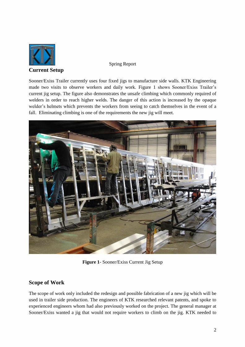
Sooner/Exiss Trailer currently uses four fixed jigs to manufacture side walls. KTK Engineering
made two visits to observe workers and daily work. Figure 1 shows Sooner/Exiss Trailer’s
current jig setup. The figure also demonstrates the unsafe climbing which commonly required of
welders in order to reach higher welds. The danger of this action is increased by the opaque
welder’s helmets which prevents the workers from seeing to catch themselves in the event of a
fall. Eliminating climbing is one of the requirements the new jig will meet.
Figure 1- Sooner/Exiss Current Jig Setup
Scope of Work
The scope of work only included the redesign and possible fabrication of a new jig which will be
used in trailer side production. The engineers of KTK researched relevant patents, and spoke to
experienced engineers whom had also previously worked on the project. The general manager at
Sooner/Exiss wanted a jig that would not require workers to climb on the jig. KTK needed to

Spring Report
3
make sure the jig did not deflect when a trailer side was being constructed. The jig needed to
increase accuracy of framing posts, window, and door placement so fewer trailers would need to
be reworked.
Physical Location
The construction of the project occurred in the Oklahoma State University Biosystems and
Agricultural Engineering (BAE) laboratory in Stillwater, OK and at the Sooner/Exiss Trailers
factory in El Reno, OK. Solidworks models were used to communicate ideas between
Sooner/Exiss Trailer and KTK Engineering. Design work was performed at Oklahoma State
University, also in Stillwater, OK.
Period of Performance
KTK Engineering Solutions’ engineers began the redesign of the jig in the Fall Semester of
2012. Design work was to be completed by December of 2012, and the final design review was
completed in the weeks of December 3rd
-14th
. The project was completed in April of 2013. The
final design was presented and the prototype delivered to the client on April 25, 2013.
Delivery Requirements
Table 1 – Delivery requirements by date and day of week
Monday 10/29/12 SOW Due
Friday 11/2/12 WBS Due
Monday 11/5/12 Task List Due
Monday 11/12/12 Engr Design Concepts Due
Monday 11/19/12 1st Draft Report Due
Monday-Friday
Friday
Monday
12/3-12/14/12
12/7/12
4/22/2013
Technical Presentation
Report due to Sooner/Exiss
Project Complete
Detailed Work
KTK began the redesign in the fall semester of 2012.
The jig needed to accommodate trailers between 5’6” and 8’6” tall and between 16’ and 42’
long. The jig needed to be structurally sound as to not deflect when in a horizontal position. The
jig also needed to accommodate the available floor space in the factory in El Reno.
The design selected is a table type jig with vertical and horizontal square tube for workers to
clamp to. The jig will rotate using an electrically powered DC motor. The jig will be balanced to
aid ease of movement. The jig will have a braking system utilizing a worm gear for workers to

Spring Report
4
be able to stop the jig in a desired position. The jig will rotate past horizontal to the backside for
welders to weld the top rail in place without having to climb on the jig. The jig will allow
workers to place components and weld without needing tape measures by incorporating a
measurement system into the jig. The welders will be able to weld in an ergonomic position,
without having to weld over their heads. The jig will accommodate moving welding hoses up off
the floor, eliminating trip hazards. The jig will also have a bottom rail or fixed toggle clamps for
welders to place the bottom rail of the trailer.
KTK spent time on this list of actions for the redesign.
Brainstorming for ideas for the redesign
Developing a scope of work
Drawing ideas in Solidworks
Calculating deflection in main center pipe
Calculating torsional deflection in center pipe
Selecting appropriate materials based on calculations
Developing different ideas for measurement system
Analyzing cost difference between different systems
Designing a 15’ prototype as a proof of concept piece
Production and testing of the prototype
Modification of the prototype based upon testing
Incorporating manager and wage workers wants and needs resulted in several design options.
Appendix 3 contains a chart of design options. This chart assisted KTK throughout the design
process.
Task List
KTK developed this task list to help organize thoughts and find the direction to pursue for the
redesign.
1) Jig Prototype
a. Redesign
i. Determination of Rotation Mechanism
1. Hydraulic
2. Counterweight
3. Manual Crank
4. Electric DC motor
ii. Create Alternative Measurement Solutions
1. Laser measurement
2. Laser projection
Spring Report
5
3. Adhesive ‘tape measure’
iii. Engineering Calculations
1. Material Determination
2. Deflection
3. # of pinions
4. Torsion
5. Tipping
6. Buckling
iv. Determine clamping locations
1. Type of clamp
2. Number of clamps
v. Solidworks Drawings
1. Create 3D model
2. Stress analysis
3. Deflection analysis
4. Create Standard Engineering Drawings
vi. Scale Model
1. Deflection Testing
2. Material Validation
3. Determine Number of Supports needed
b. Purchasing
i. Price Lasers/Measurement Systems
1. Design System suitable
ii. Center Pipe Material
iii. Table Materials
iv. Clamps
v. Measurement System
Work Breakdown
1) Jig Prototype
a. Redesign
i. Scale Model
1. Deflection Testing
2. Material Validation
3. Number of Supports needed
ii. Solidworks Drawings
1. Stress analysis
2. Deflection analysis
iii. Engineering Calculations
Spring Report
6
1. Material Determination
2. Deflection
3. # of pinions
4. Torsion
5. Tipping
6. Buckling
iv. Determine clamping locations
1. Type of clamp
2. Number of clamps
b. Rotation Jig
i. Rotation Mechanism
1. Hydraulic
2. Counterweight
3. Manual Crank
4. Electric DC Motor
c. Price Lasers/Measurement Systems
i. Design System suitable
d. Alternative Solutions
i. Everything that may not be financially feasible or practical
Payment Schedule
KTK did not receive compensation for the design work or the manufacturing of the jig. All
materials were purchased by Sooner/Exiss. Sooner/Exiss set a ceiling of $20,000 for all
expenses.
Acceptance Criteria
Sooner/Exiss required a jig that can produce at least 10 trailers per day, a 30% increase in
manufacturing, while being ergonomic and pleasing for workers. The jig must also improve
worker’s safety; the workers must not be required to climb on the jig, reducing injuries from
stepping down off the older version of the jig. In addition, welding cords need to be moved off
the ground, or away from walking spaces, reducing trip hazards.
Special Requirements
Due to the nature of the project, KTK was required to travel to Sooner/Exiss when a site visit
was necessary. Don Lake, Applications Engineering Extension Agent for Oklahoma State
University was accommodated by meeting half way, and meeting at times convenient to him
when he was in Stillwater, OK, KTK’s base location. In addition, KTK collaborated with Mike
Raymond with the Oklahoma Manufacturing Alliance, and Aaron Cain and Dr. Robert Taylor,

Spring Report
7
both with the New Product Development Center at Oklahoma State University. Biweekly,
conference calls were arranged with KTK, Dr. Paul Weckler, Larry Zahasky, Don Lake, and
Mike Raymond to discuss the progress being made on the project.
Technical Analysis
Existing jigs for trailer side framing consist of steel square and round tube welded into a table-
like apparatus. For example, Featherlite trailers has a set of jigs very similar to those found at
Sooner/Exiss Trailer’s manufacturing plant. However, Featherlite has positioning jigs (Figure 2).
It is worth mentioning that Featherlite does make use of a robotic welding system, which
precision welds the frame for the gooseneck. The pieces are placed upon a rotating jig with
clamps them in place before the robot welds them (Featherlite, 2009)
Figure 2 - Featherlight trailer side frame jig (Featherlite, 2009)
The jigs are made of heavy steel tube which is welded together. Considering this, there should
not be any maintenance costs associated with the jig, unless a cutting operation or other activity
performed by a welder was to damage it by melting or annealing the metal. Considering the
melting point of steel is greater than that of aluminum, (2600-2800 oF for steel, vs. 660
oF for
aluminum) it is unlikely that any welding or cutting operations should involve high enough
temperature to damage the jig. In addition, steel does not transform into austenite below 738 oC

Spring Report
8
(1360.4 oF), which provides evidence that the steel jig should not be in danger of annealing
(assuming cold rolled steel is used to build the jig). Due to these factors, KTK engineers chose to
use mainly steel components in the construction of the new welding jig.
It would be possible to create a framing jig which can rotate and translate, but only found
one working example of a jig which takes advantage of this ability. The example can be found in
Figure 3. It should be noted that any jig which incorporates moving components will require
more maintenance. At the very least, grease will need to be pumped into the collars holding the
rotating shaft.
Figure 3 - Hydraulic, movable trailer framing jig (http://www.mrtrailer.com/t_pic/titan157.jpg)
According to Sooner/Exiss Trailers employees, they did have a rotating jig that was in use at one
point in the past. However, the jig had unacceptable deformation when in the horizontal position.
Additionally, the jig was unpowered and had to be rotated by hand. The cost of production and
the space required to accommodate a jig which rotates is also an issue.
Several safety concerns have been associated with the current jigs in use. First, the welders are
often required to weld over their heads leading to rotator cuff injuries. Secondly, it creates the
potential for sparks to fall into the face of the welder. In addition, the welders must climb onto
the frame itself to reach some weld points, creating a hazard when stepping off the jig, as seen on
a site visit when KTK was told about an employee who suffered a broken foot from just this
hazard.

Spring Report
9
Any powered jig design will have to incorporate a solution to the trip hazard created by any
hoses or cords which provide power to the jig, unless it uses manual rotation. Along the same
lines, any pinch points and moving components of the jig will require shielding to prevent injury
to the welders and a failsafe will be required to prevent accidental operation of the jig (for
example, a cover over the operation switch might add protection against accidental contact).
Patent Searches
KTK found several relevant patents. The first is a patent for rail box car under frames which uses
clamps attached to the jig table to secure the side sills to the center sill. One of the most relevant
points made is that the non-fixed clamps used in design of the jig allow the rail car frame to be
removed despite expansion in the metal caused by the welding operations. This will need to be a
consideration which is examined, should any fixed dimension jigs be designed by KTK (Shipley,
1951).
The second patent, by Sellers, L. (1979), filed for a jig to fabricate side walls for houses.
Included in the patent are designs for movable, U-shaped guides which can be used to place
studs at the desired center distances. This could help KTK to design a system by which the trailer
side ribs can be placed at the desired center to center intervals quickly and precisely. This would
help KTK to meet one of the clients most fervently expressed design goals: reduction in the use
of measuring tapes and hand measurement.
The third patent found describes a hand-held jig which can be adjusted using a bolt and wing-nut
assembly to place framing studs at the proper center distances. This offers KTK a possible
alternative method for placing the trailer ribs which may or may not appeal more to the
manufacturing personnel at Sooner/Exiss Trailers. However, it is possible that any design
produced by KTK which was similar could violate the patent as it was issued in 1997 and is
therefore still in effect (Bingham and Stone, 1997).
Engineering Calculations
Weight
The weight of each component and the overall jig weight were calculated based on known
specific weights for each component, the values were then checked with Solidwork’s mass
properties tool, the hand calculations can be seen in Table 2 and

Spring Report
10
Table 3.
Table 2 – Weight breakdown for the prototype section jig (note: sheet metal components, the
gussets and sheet metal in the stands have a specific weight in lb/ft2 and the length field is the
area in ft2)
Type Specific Weight
(lb/ft) Length
(ft) Weight
(lb)
SCALE PROTOTYPE
Table (x1)
6x2x3/16 St. Tube 9.42 88.7 835
gusset 7.5 2.44 18.27
Total
853.27
Stand (x2)
2x2x3/16 St. Tube 4.32 23 99.4
Girdle
Half pipe (8" sch 40) 28.55 1 28.6
sheet metal 7.5 1.36 10.2
Total
138.2
Center Shaft (6" sch 40) 18.97 15 284.55
TOTAL 1276

Spring Report
11
Table 3 – Weight breakdown for the full jig (note: sheet metal components, the gussets and sheet
metal in the stands have a specific weight in lb/ft2 and the length field is the area in ft
2)
Type Specific Weight
(lb/ft) Length
(ft) Weight
(lb)
FULL JIG
Table (x1)
6x2x3/16 St. Tube 9.42 248.7 2342
gusset 7.5 6.09 45.66
total
2387.66
Stand (x5)
2x2x3/16 St. Tube 4.32 23 99.4
Girdle
Half pipe (8" sch 40) 28.55 1 28.6
sheet metal 7.5 1.36 10.2
total
138.2
Center Shaft (6" sch 40) 18.97 42 796.7
TOTAL 3323
Deflection
Deflection within the main beam was calculated to ensure that the jig would not sag more than
1/32” which satisfied the requirement that sidewalls built in a lay-flat configuration would not
exhibit unacceptable deformation from the welding jig. Equation 1, found in Appendix 1, was
used to simulate deflection in any free span of the jig as a simply supported beam with a
distributed load.
Microsoft Excel was then used to create an optimization sheet which would allow the user to
determine the maximum span of material which would not result in more than the maximum
allowed deflection (Figure 4).

Spring Report
12
Figure 4 - Output of deflection optimization calculation
As can be seen above, the run resulted in a 10 ft span meeting the 0.0026 ft (1/32 in) maximum
deflection allowance with a calculated deflection of 0.0022 ft within each 10 ft span.
Torsion
The torsion of the center pipe was calculated by hand and using computer software based finite
element analysis (FEA). Hand calculations showed that the torsional deflection of the center pipe
would be .988 degrees with a 250 pound point load on the top outer corner of the table, assuming
one side fixed with a brake. This torsional deflection relates into a 1.655 inch deflection total at
the outmost post of the table. Half of that deflection is the top of the table rotating down due to
the point load, and the other half is the bottom of the table rotating up. This torsional deflection
is considered worst case scenario, with a 42’ trailer being put on the table and a worker climbing
on the jig. Equations to find the torsional deflection can be found in Appendix 1. Solidworks was
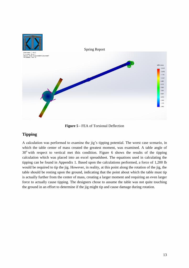
utilized to do a secondary analysis on the torsional deflection. A simplified model was used,
shown in Figure 5. The results from Solidworks are 1.1 inch total deflection, half from the top,
half from the bottom. This value was similar to that found by the hand calculations.
Spring Report
13
Figure 5 - FEA of Torsional Deflection
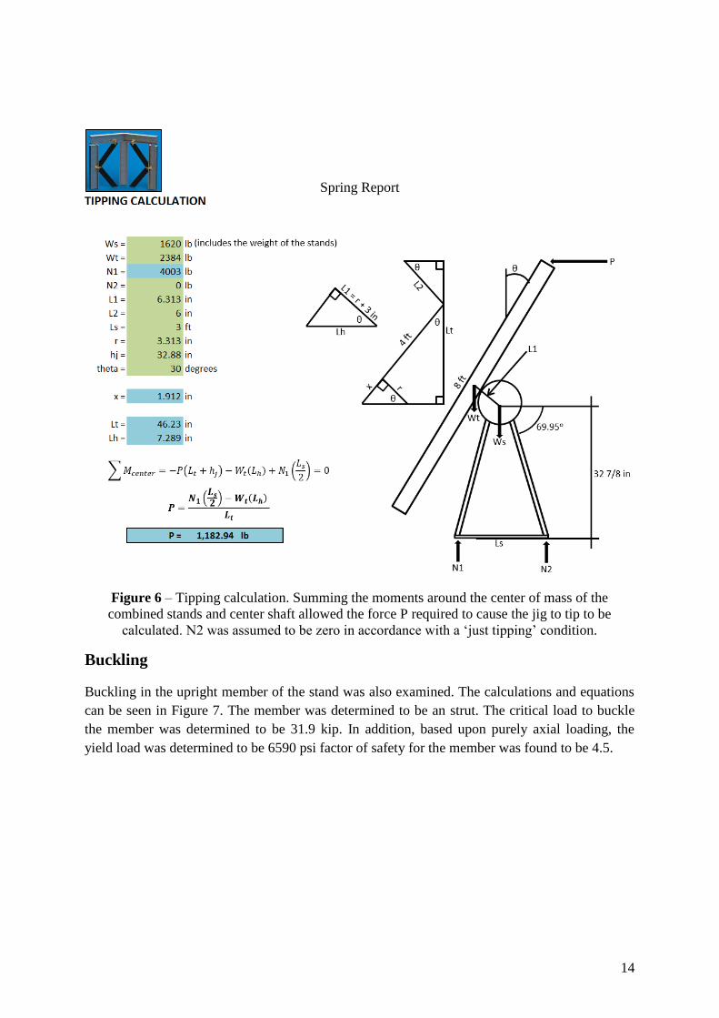
Tipping
A calculation was performed to examine the jig’s tipping potential. The worst case scenario, in
which the table center of mass created the greatest moment, was examined. A table angle of
30o with respect to vertical met this condition. Figure 6 shows the results of the tipping
calculation which was placed into an excel spreadsheet. The equations used in calculating the
tipping can be found in Appendix 1. Based upon the calculations performed, a force of 1,200 lb
would be required to tip the jig. However, in reality, at this point along the rotation of the jig, the
table should be resting upon the ground, indicating that the point about which the table must tip
is actually further from the center of mass, creating a larger moment and requiring an even larger
force to actually cause tipping. The designers chose to assume the table was not quite touching
the ground in an effort to determine if the jig might tip and cause damage during rotation.
Spring Report
14
Figure 6 – Tipping calculation. Summing the moments around the center of mass of the
combined stands and center shaft allowed the force P required to cause the jig to tip to be
calculated. N2 was assumed to be zero in accordance with a ‘just tipping’ condition.
Buckling
Buckling in the upright member of the stand was also examined. The calculations and equations
can be seen in Figure 7. The member was determined to be an strut. The critical load to buckle
the member was determined to be 31.9 kip. In addition, based upon purely axial loading, the
yield load was determined to be 6590 psi factor of safety for the member was found to be 4.5.

Spring Report
15
Figure 7 – Buckling calculations.
New Stand Deformation
The new girdle design was examined using FEA. The base of the stand was fixed and then a
distributed load of 328 lb directly downwards over the half pipe at the bottom of the girdle was
applied (the force applied can be seen in Figure 8.

Spring Report
16
Figure 8 – Fixture (left) and load (right) conditions applied to examine girdle yielding.
The results of the simulation using these conditions are as follows (Figure 9 and Figure 10):
Figure 9 – Simulation stresses found in the stand, max stress is 19.5 MPa (2.83 ksi)

Spring Report
17
Figure 10 – Simulated deformation within the stand. Deformation is at a scale of 3910.24:1. The
maximum deformation is 0.025 mm (9.84x10⁻⁴
in).
The maximum calculated stress was 2.83 ksi, well below the yield stress for steel (~30 ksi for
1020 HR, a mild, hot rolled steel). Moreover, the simulation results showed a deflection of 0.025
mm or 0.000984 in. In addition, our results demonstrated the middle plate shown in the analysis
above did not significantly aid in reducing deformation. Therefore, it was removed in the
subsequent design.
Current Design
Figure 11 displays the design that KTK Engineering has created for the base model jig.
Dimensions are 42’ long by 8’ wide. The table is made out of 2”x 6” x 3/16” rectangular steel
tubing. The stands are made out of 2” x 2” x 3/16” square tubing, welded together. The table will
be welded to the main rotating shaft, which will be 6” Schedule 40 pipe. There will be fixed
toggle clamps on the bottom of each vertical support. The table will rotate to the ground in the
front, and approximately 20 degrees past horizontal in the back. The back of the jig will have a
steel stop that prevents further rotation. The jig is powered by a DC electric motor and worm
gear.

Spring Report
18
Figure 11 - View of Rotating Jig Design
Prototype Design
KTK Engineering is producing a prototype in order for Sooner/Exiss to make an executive
decision to build a full scale jig. The prototype jig will be built to full length jig specifications,
but will only be 15 foot long, as opposed to 42 foot. The jig will be fully rotational. After it is
built it can be used in Sooner/Exiss’s facility to manufacture doors and windows, if desired.
Prototype Manufacturing
Base materials for the prototype were ordered by Sooner/Exiss through their distributor and were
shipped to Biosystems machine lab for assembly as shown in Figure 12.
Figure 12- Center shaft and tubing
Spring Report
19
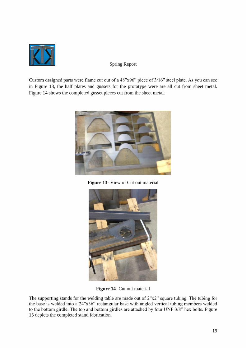
Custom designed parts were flame cut out of a 48”x96” piece of 3/16” steel plate. As you can see
in Figure 13, the half plates and gussets for the prototype were are all cut from sheet metal.
Figure 14 shows the completed gusset pieces cut from the sheet metal.
Figure 13- View of Cut out material
Figure 14- Cut out material
The supporting stands for the welding table are made out of 2”x2” square tubing. The tubing for
the base is welded into a 24”x36” rectangular base with angled vertical tubing members welded
to the bottom girdle. The top and bottom girdles are attached by four UNF 3/8” hex bolts. Figure
15 depicts the completed stand fabrication.

Spring Report
20
Figure 15- Initial stand height
The welding table is made out 2”x 6’x 3/16” rectangular tubing. The 15’ pieces of tubing were
placed on the ground and the distance between them were measured to drawing specifications.
The 8’ pieces of tubing were placed perpendicular to the 15’ pieces and measured to drawing
specs. The pieces were squared and tacked into place. Figure 16 shows the center shaft with the
gussets premounted being measured and tacked into place.
Figure 16- Laying out the center shaft into table
Spring Report
21
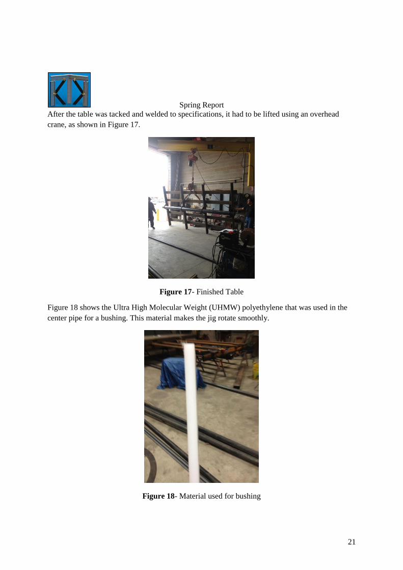
After the table was tacked and welded to specifications, it had to be lifted using an overhead
crane, as shown in Figure 17.
Figure 17- Finished Table
Figure 18 shows the Ultra High Molecular Weight (UHMW) polyethylene that was used in the
center pipe for a bushing. This material makes the jig rotate smoothly.
Figure 18- Material used for bushing

Spring Report
22
Figure 19 shows how the UHMW used for the bushing was form fitted to the center pipe stand.
The UHMW was heated such that it would form to the stand. The UHMW was then pressed
down with a pipe of the same size diameter of the center shaft. After the UHMW cooled the
sample center shaft was removed to place the full center shaft in.
Figure 19- Form fitting bushing to stand
Figure 20 depicts the sample center shaft holding the bushing material in place during cooling.
Figure 20- Initial bushing test
Spring Report
23
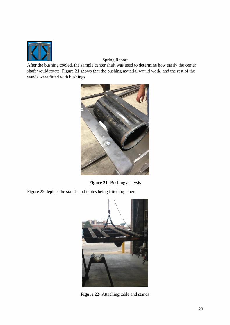
After the bushing cooled, the sample center shaft was used to determine how easily the center
shaft would rotate. Figure 21 shows that the bushing material would work, and the rest of the
stands were fitted with bushings.
Figure 21- Bushing analysis
Figure 22 depicts the stands and tables being fitted together.
Figure 22- Attaching table and stands

Spring Report
24
Figure 23 shows an error that was not diagnosed before manufacturing. The material of the
stands had been changed from pipe to tubing, and the same dimensions were used, making the
stands too tall. This was later fixed using simple engineering calculations.
Figure 23- Initial stand height comparison. 5’3” girl vs table height.
Figure 24 shows that the stands had been modified from the previous dimensions, to an
acceptable height. This modification required the stand legs to be notched at a 60 degree angle to
preserve the integrity of the degree of the table when it is sitting on the ground.
Figure 24- Modified legs of the table

Spring Report
25
Figure 25 depicts the table integrity while another senior design project needed to be worked on.
The table has been used for welding, before it was attached to the stands. The table showed no
visible deformation.
Figure 25- Testing
Cost Analysis
KTK performed an analysis of the materials costs for both the 15’ prototype jig (Table 4) and
the full 42’ final jig (Table 5). The full price for the prototype components came out to just over
$1,300.00 and the full jig material cost came up to $3,100.00, both significantly under the
original $20,000.00 budget.

Spring Report
26
Table 4 - Price of all materials for the 15’ prototype
Base and Table Prototype Original Materials
Parts List
Quantity
(ft) Price/ft Total
2x6in Rectangular
Tubing 92 $5.10 $469.20
6-5/8in Drill Stem Pipe 15 $40.00 $600.00
Drawn over mandrel Pipe 4 $48.90 $195.60
2-3/8in Pipe 47 $1.90 $89.30
1/2in Steel Rod 15 $0.78 $11.70
HH-225D Toggle Clamp 4 $25.00 $100.00
UHMW Plastic 16 $9.68 $154.88
40 Roller Chain 10 $3.53 $35.30
80 Tooth Sprocket 1 $74.22 $74.22
Idler Sprocket 1 $27.68 $27.68
Adhesive Backed Ruler 2 $29.70 $59.40
Total
$1,817.28
New Materials
Parts List
Quantity
(ft) Price/ft Total
2x6in Rectangular
Tubing 92 $5.10 $469.20
2x2in Square Tubing 47 $2.25 $105.75
6in Schedule 40 Pipe 15 $11.24 $168.60
8in Schedule 40 Pipe 2 $16.43 $32.86
3/16x48x96in Steel Plate 1 $101.00 $101.00
HH-225D Toggle Clamp 4 $25.00 $100.00
UHMW Plastic 16 $9.68 $154.88
40 Roller Chain 10 $3.53 $35.30
80 Tooth Sprocket 1 $74.22 $74.22
Idler Sprocket 1 $27.68 $27.68
Adhesive Backed Ruler 2 $29.70 $59.40
Total
$1,328.89

Spring Report
27
Table 5 – Price of all materials for the full jig
Base and Table Full Jig Original Materials
Parts List
Quantity
(ft) Price/ft Total
2x6in Rectangular
Tubing 248 $5.10 $1,264.80
6-5/8in Drill Stem Pipe 42 $40.00 $1,680.00
Drawn over mandrel Pipe 10 $48.90 $489.00
2-3/8in Pipe 120 $1.90 $228.00
1/2in Steel Rod 42 $0.78 $32.76
HH-225D Toggle Clamp 10 $25.00 $250.00
UHMW Plastic TBD
40 Roller Chain 10 $3.53 $35.30
80 Tooth Sprocket 1 $74.22 $74.22
Idler Sprocket 1 $27.68 $27.68
Adhesive Backed Ruler 2 $79.20 $158.40
Total
$4,240.16
New Materials
Parts List
Quantity
(ft) Price/ft Total
2x6in Rectangular
Tubing 248 $5.10 $1,264.80
2x2in Square Tubing 120 $2.25 $270.00
6in Schedule 40 Pipe 42 $11.24 $472.08
8in Schedule 40 Pipe 5 $16.43 $82.15
3/16x48x96in Steel Plate 2.5 $101.00 $252.50
HH-225D Toggle Clamp 10 $25.00 $250.00
UHMW Plastic 27 $9.68 $261.36
40 Roller Chain 10 $3.53 $35.30
80 Tooth Sprocket 1 $74.22 $74.22
Idler Sprocket 1 $27.68 $27.68
Adhesive Backed Ruler 2 $79.20 $158.40
Total
$3,148.49

Spring Report
28
Recommendations
KTK recommends that Sooner/Exiss Trailer purchase two basic jigs for their production line. We
also recommend that the jigs be motorized with adhesive rules and toggle clamps.
Modifications
After prototype demonstrations Sooner/Exiss recommended that some modifications be made to
the jig. They recommended that the stands be made vertically taller to increase the angle of the
jig when it is resting on the ground. The adhesive backed rules need to be recessed into the jig
itself to protect against abrasive damage from the trailer sides. The toggle clamps and bottom
vertical members should be recessed to allow for easy installation of the bottom rail.
References
Bingham, G. A. and V. C. Stone. 1997. Adjustable framing jig. U.S. Patent No. 5628119.
Featherlite Factory Tour, Ahead of the Curve. 2009. Mr. Truck. Available at
http://www.mrtrailer.com/featherlite_factory.htm. Accessed 12 October 2012.
Sellers, L. 1979. Wall component fabricating jig. U.S. Patent No. 4154436
Shipley, T. G. 1951. Welding Jig for car underframes. U.S. Patent No. 2553947
http://www.universaltrailer.com/
http://www.soonertrailers.com/
http://www.exiss.com/

Spring Report
29
Appendix 1
Equations Used:
Horizontal Deflection
( )
Torsional Deflection
G=Modulus of Rigidity
= Torsional Deflection T=Torque
l=length J=Polar moment of Inertia
Tipping
∑ ( ) ( ) (
)
(
) ( )
P= Force Normal Force
y = deflection
W = distributed load
E = Young’s modulus
I = Moment of inertia
x = location along beam
l = total length

Spring Report
30
Buckling
Euler Intermediate Strut
( )
(
)

Spring Report
31
Appendix 2
Gantt Chart- Microsoft Project

S
prin
g R
epo
rt
32
Ap
pen
dix
3
Flo
w C
ha
rt of G
enera
ted D
esign
Op
tion
s
No
Clim
bin
g
Mo
ve
Jig
Mo
ve
Pe
op
le
Mo
ve
Jig
Se
qw
ay
Pla
tform
with
La
dd
er
Lift
Ele
ctric
Hy
dra
ulic
Pn
eu
ma
tic
Ro
tatio
n
Ve
rtica
l Tra
nsla
tion
Ve
rtica
l Tra
nsla
tion
Ha
nd
Po
we
red
Ha
nd
Po
we
red
with
m
ech
an
ica
l assis
t
Po
we
red
Hy
dra
ulic
Pn
eu
ma
tic
Ele
ctric
Mo
ve
jig re
lativ
e to
flo
or
Hy
dra
ulic
Pn
eu
ma
tic
Ele
ctric
La
se
r Dis
tan
ce
M
ea
su
re
Atta
ch
Ru
ler(s
) to jig
With
Ta
ble
Sa
w
Fe
nce
Ha
nh
eld
Use
mo
va
ble
C-
cla
mp
s to
loca
te
Ve
rtica
l me
mb
ers
Use
two
rule
rs to
p
lace
co
mp
on
en
ts in
sq
ua
re

Spring Report
33
Appendix 4
CAD Drawings:

1
42
3
9
5
L
FRON
T VIEW
DETA
IL L SC
ALE 1 : 5
67
8
UNLESS O
THERWISE SPEC
IFIED:A
LL MA
TERIALS A
RE MILD
HOT
•RO
LLED STEEL
•PIPE IS SC
HEDULE 40
•
ITEM N
O.
PART N
UMBER
QTY.
1Stand
52
6.625 in x ~21 ft C
enter Pipe2
3table
14
Sprocket1
5gusset
106
UNF 3/8-24 1"
5
73/8" FLA
T WA
SHER5
8UN
F 3/8-24 LOC
KNUT
59
Bushing5
JIG - SIN
GLE SEC
TION
DO
NO
T SCA
LE DRA
WIN
GSHEET 1 O
F 20
2/3/13KD
R
UNLESS O
THERWISE SPEC
IFIED:
SCA
LE: 1:128WEIG
HT:
REVD
WG
. NO
.
A SIZE
TITLE:
NA
ME
DA
TE
CO
MM
ENTS:
Q.A
.
MFG
APPR.
ENG
APPR.
CHEC
KED
DRA
WN
FINISH
MA
TERIAL
INTERPRET G
EOM
ETRICTO
LERAN
CIN
G PER:
DIM
ENSIO
NS A
RE IN IN
CHES
TOLERA
NC
ES:FRA
CTIO
NA
LA
NG
ULAR: M
AC
H BEN
D
TWO
PLAC
E DEC
IMA
L THREE PLA
CE D
ECIM
AL
APPLIC
ATIO
N
USED O
NN
EXT ASSY
PROPRIETA
RY AN
D CO
NFIDEN
TIAL
THE INFO
RMA
TION
CO
NTA
INED
IN THIS
DRA
WIN
G IS THE SO
LE PROPERTY O
F<IN
SERT CO
MPA
NY N
AM
E HERE>. AN
Y REPRO
DUC
TION
IN PA
RT OR A
S A W
HOLE
WITHO
UT THE WRITTEN
PERMISSIO
N O
F<IN
SERT CO
MPA
NY N
AM
E HERE> IS PRO
HIBITED.
54
32
1
REVISIO
NB

25278
"
E
8.63
7
58"
DETA
IL E SC
ALE 1 : 5
6 IN SC
H 40CEN
TER SHAFT
DO
NO
T SCA
LE DRA
WIN
GSHEET 2 O
F 20
2/3/13KD
R
UNLESS O
THERWISE SPEC
IFIED:
SCA
LE: 1:64W
EIGHT:
REVD
WG
. NO
.
A SIZE
TITLE:
NA
ME
DA
TE
CO
MM
ENTS:
Q.A
.
MFG
APPR.
ENG
APPR.
CHEC
KED
DRA
WN
FINISH
MA
TERIAL
INTERPRET G
EOM
ETRICTO
LERAN
CIN
G PER:
DIM
ENSIO
NS A
RE IN IN
CHES
TOLERA
NC
ES:FRA
CTIO
NA
LA
NG
ULAR: M
AC
H BEN
D
TWO
PLAC
E DEC
IMA
L THREE PLA
CE D
ECIM
AL
APPLIC
ATIO
N
USED O
NN
EXT ASSY
PROPRIETA
RY AN
D CO
NFIDEN
TIAL
THE INFO
RMA
TION
CO
NTA
INED
IN THIS
DRA
WIN
G IS THE SO
LE PROPERTY O
F<IN
SERT CO
MPA
NY N
AM
E HERE>. AN
Y REPRO
DUC
TION
IN PA
RT OR A
S A W
HOLE
WITHO
UT THE WRITTEN
PERMISSIO
N O
F<IN
SERT CO
MPA
NY N
AM
E HERE> IS PRO
HIBITED.
54
32
1
REVISIO
NB

B
1
2
7
6
5
1/8TYP - 4 PLA
CES
DETA
IL B SC
ALE 1 : 1
3
4
ITEM N
O.
PART N
UMBER
DESC
RIPTION
QTY.
1G
irdle
SUBASSEM
BLY1
2Top_G
irdle
SUBASSEM
BLY1
3UN
F 3/8-24 HEX BOLT
44
UNF 3/8-24 HEX N
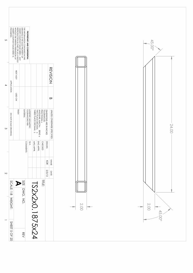
UT4
5TS2x2x3/16x24
26
TS2x2x0.1875x362
7TS2x2x3/16x40
4
STAN
D
DO
NO
T SCA
LE DRA
WIN
GSHEET 3 O
F 20
2/3/13KD
R
UNLESS O
THERWISE SPEC
IFIED:
SCA
LE: 1:24W
EIGHT:
REVD
WG
. NO
.
A SIZE
TITLE:
NA
ME
DA
TE
CO
MM
ENTS:
Q.A
.
MFG
APPR.
ENG
APPR.
CHEC
KED
DRA
WN
FINISH
MA
TERIAL
INTERPRET G
EOM
ETRICTO
LERAN
CIN
G PER:
DIM
ENSIO
NS A
RE IN IN
CHES
TOLERA
NC
ES:FRA
CTIO
NA
LA
NG
ULAR: M
AC
H BEN
D
TWO
PLAC
E DEC
IMA
L THREE PLA
CE D
ECIM
AL
APPLIC
ATIO
N
USED O
NN
EXT ASSY
PROPRIETA
RY AN
D CO
NFIDEN
TIAL
THE INFO
RMA
TION
CO
NTA
INED
IN THIS
DRA
WIN
G IS THE SO
LE PROPERTY O
F<IN
SERT CO
MPA
NY N
AM
E HERE>. AN
Y REPRO
DUC
TION
IN PA
RT OR A
S A W
HOLE
WITHO
UT THE WRITTEN
PERMISSIO
N O
F<IN
SERT CO
MPA
NY N
AM
E HERE> IS PRO
HIBITED.
54
32
1
REVISIO
NB

D D
1.00
SECTIO
N D
-D
SCA
LE 1 : 15
1/81-2
1/81.5
G
TYP - 4 PLAC
ES
STAN
D
DO
NO
T SCA
LE DRA
WIN
GSHEET 4 O
F 20
UNLESS O
THERWISE SPEC
IFIED:
SCA
LE: 1:24W
EIGHT:
REVD
WG
. NO
.
A SIZE
TITLE:
NA
ME
DA
TE
CO
MM
ENTS:
Q.A
.
MFG
APPR.
ENG
APPR.
CHEC
KED
DRA
WN
FINISH
MA
TERIAL
INTERPRET G
EOM
ETRICTO
LERAN
CIN
G PER:
DIM
ENSIO
NS A
RE IN IN
CHES
TOLERA
NC
ES:FRA
CTIO
NA
LA
NG
ULAR: M
AC
H BEN
D
TWO
PLAC
E DEC
IMA
L THREE PLA
CE D
ECIM
AL
APPLIC
ATIO
N
USED O
NN
EXT ASSY
PROPRIETA
RY AN
D CO
NFIDEN
TIAL
THE INFO
RMA
TION
CO
NTA
INED
IN THIS
DRA
WIN
G IS THE SO
LE PROPERTY O
F<IN
SERT CO
MPA
NY N
AM
E HERE>. AN
Y REPRO
DUC
TION
IN PA
RT OR A
S A W
HOLE
WITHO
UT THE WRITTEN
PERMISSIO
N O
F<IN
SERT CO
MPA
NY N
AM
E HERE> IS PRO
HIBITED.
54
32
1
2.00
2.00 45.00°
45.00°
24.00
REVISIO
NB
DO
NO
T SCA
LE DRA
WIN
GSHEET 5 O
F 20
2/3/13KD
R
UNLESS O
THERWISE SPEC
IFIED:
SCA
LE: 1:8W
EIGHT:
REVD
WG
. NO
.
A SIZE
TITLE:
NA
ME
DA
TE
CO
MM
ENTS:
Q.A
.
MFG
APPR.
ENG
APPR.
CHEC
KED
DRA
WN
FINISH
MA
TERIAL
INTERPRET G
EOM
ETRICTO
LERAN
CIN
G PER:
DIM
ENSIO
NS A
RE IN IN
CHES
TOLERA
NC
ES:FRA
CTIO
NA
LA
NG
ULAR: M
AC
H BEN
D
TWO
PLAC
E DEC
IMA
L THREE PLA
CE D
ECIM
AL
APPLIC
ATIO
N
USED O
NN
EXT ASSY
PROPRIETA
RY AN
D CO
NFIDEN
TIAL
THE INFO
RMA
TION
CO
NTA
INED
IN THIS
DRA
WIN
G IS THE SO
LE PROPERTY O
F<IN
SERT CO
MPA
NY N
AM
E HERE>. AN
Y REPRO
DUC
TION
IN PA
RT OR A
S A W
HOLE
WITHO
UT THE WRITTEN
PERMISSIO
N O
F<IN
SERT CO
MPA
NY N
AM
E HERE> IS PRO
HIBITED.
54
32
1
TS2x2x0.1875x24

2.00 45.00°
45.00°
36.00
2.00
BREV
ISION
TS2x2x0.1875x36
DO
NO
T SCA
LE DRA
WIN
GSHEET 6 O
F 20
2/3/13KD
R
UNLESS O
THERWISE SPEC
IFIED:
SCA
LE: 1:12W
EIGHT:
REVD
WG
. NO
.
A SIZE
TITLE:
NA
ME
DA
TE
CO
MM
ENTS:
Q.A
.
MFG
APPR.
ENG
APPR.
CHEC
KED
DRA
WN
FINISH
MA
TERIAL
INTERPRET G
EOM
ETRICTO
LERAN
CIN
G PER:
DIM
ENSIO
NS A
RE IN IN
CHES
TOLERA
NC
ES:FRA
CTIO
NA
LA
NG
ULAR: M
AC
H BEN
D
TWO
PLAC
E DEC
IMA
L THREE PLA
CE D
ECIM
AL
APPLIC
ATIO
N
USED O
NN
EXT ASSY
PROPRIETA
RY AN
D CO
NFIDEN
TIAL
THE INFO
RMA
TION
CO
NTA
INED
IN THIS
DRA
WIN
G IS THE SO
LE PROPERTY O
F<IN
SERT CO
MPA
NY N
AM
E HERE>. AN
Y REPRO
DUC
TION
IN PA
RT OR A
S A W
HOLE
WITHO
UT THE WRITTEN
PERMISSIO
N O
F<IN
SERT CO
MPA
NY N
AM
E HERE> IS PRO
HIBITED.
54
32
1
1
32
1/8TYP - 2 PLA
CES
1/83
TYP - 2 PLAC
ES
1/84
TYP - 2 PLAC
ES
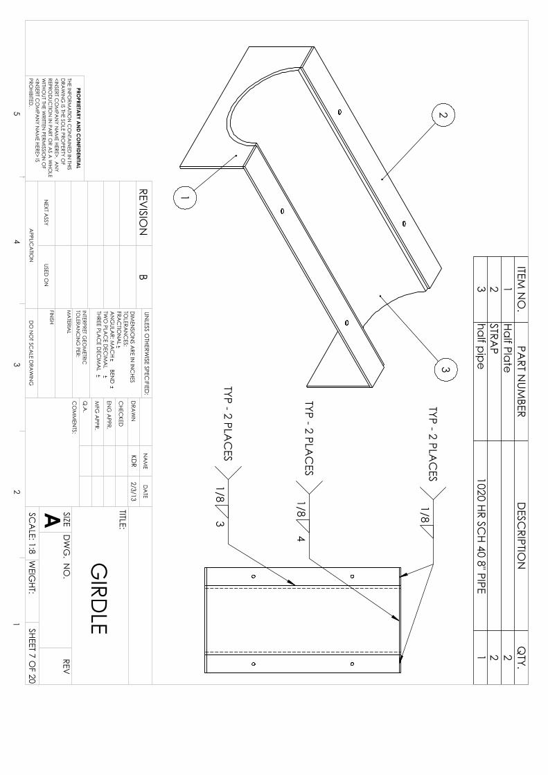
ITEM N
O.
PART N
UMBER
DESC
RIPTION
QTY.
1Half Plate
22
STRAP
23
half pipe1020 HR SC
H 40 8" PIPE1
GIRD
LE
DO
NO
T SCA
LE DRA
WIN
GSHEET 7 O
F 20
2/3/13KD
R
UNLESS O
THERWISE SPEC
IFIED:
SCA
LE: 1:8W
EIGHT:
REVD
WG
. NO
.
A SIZE
TITLE:
NA
ME
DA
TE
CO
MM
ENTS:
Q.A
.
MFG
APPR.
ENG
APPR.
CHEC
KED
DRA
WN
FINISH
MA
TERIAL
INTERPRET G
EOM
ETRICTO
LERAN
CIN
G PER:
DIM
ENSIO
NS A
RE IN IN
CHES
TOLERA
NC
ES:FRA
CTIO
NA
LA
NG
ULAR: M
AC
H BEN
D
TWO
PLAC
E DEC
IMA
L THREE PLA
CE D
ECIM
AL
APPLIC
ATIO
N
USED O
NN
EXT ASSY
PROPRIETA
RY AN
D CO
NFIDEN
TIAL
THE INFO
RMA
TION
CO
NTA
INED
IN THIS
DRA
WIN
G IS THE SO
LE PROPERTY O
F<IN
SERT CO
MPA
NY N
AM
E HERE>. AN
Y REPRO
DUC
TION
IN PA
RT OR A
S A W
HOLE
WITHO
UT THE WRITTEN
PERMISSIO
N O
F<IN
SERT CO
MPA
NY N
AM
E HERE> IS PRO
HIBITED.
54
32
1
BREV
ISION

1318
"
6.00
214
" 2
14"
R4.31
316
" HALF PLA
TE
DO
NO
T SCA
LE DRA
WIN
GSHEET 8 O
F 20
2/3/13KD
R
UNLESS O
THERWISE SPEC
IFIED:
SCA
LE: 1:4W
EIGHT:
REVD
WG
. NO
.
A SIZE
TITLE:
NA
ME
DA
TE
CO
MM
ENTS:
Q.A
.
MFG
APPR.
ENG
APPR.
CHEC
KED
DRA
WN
FINISH
MA
TERIAL
INTERPRET G
EOM
ETRICTO
LERAN
CIN
G PER:
DIM
ENSIO
NS A
RE IN IN
CHES
TOLERA
NC
ES:FRA
CTIO
NA
LA
NG
ULAR: M
AC
H BEN
D
TWO
PLAC
E DEC
IMA
L THREE PLA
CE D
ECIM
AL
APPLIC
ATIO
N
USED O
NN
EXT ASSY
PROPRIETA
RY AN
D CO
NFIDEN
TIAL
THE INFO
RMA
TION
CO
NTA
INED
IN THIS
DRA
WIN
G IS THE SO
LE PROPERTY O
F<IN
SERT CO
MPA
NY N
AM
E HERE>. AN
Y REPRO
DUC
TION
IN PA
RT OR A
S A W
HOLE
WITHO
UT THE WRITTEN
PERMISSIO
N O
F<IN
SERT CO
MPA
NY N
AM
E HERE> IS PRO
HIBITED.
54
32
1
BREV
ISION
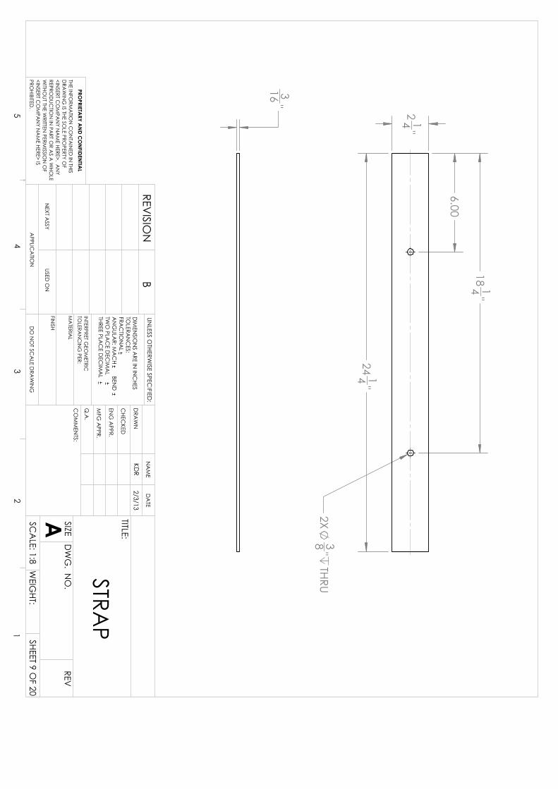
316
" 214
"
2414
"
6.00
1814
"
2X38
"THRU
STRAP
DO
NO
T SCA
LE DRA
WIN
GSHEET 9 O
F 20
2/3/13KD
R
UNLESS O
THERWISE SPEC
IFIED:
SCA
LE: 1:8W
EIGHT:
REVD
WG
. NO
.
A SIZE
TITLE:
NA
ME
DA
TE
CO
MM
ENTS:
Q.A
.
MFG
APPR.
ENG
APPR.
CHEC
KED
DRA
WN
FINISH
MA
TERIAL
INTERPRET G
EOM
ETRICTO
LERAN
CIN
G PER:
DIM
ENSIO
NS A
RE IN IN
CHES
TOLERA
NC
ES:FRA
CTIO
NA
LA
NG
ULAR: M
AC
H BEN
D
TWO
PLAC
E DEC
IMA
L THREE PLA
CE D
ECIM
AL
APPLIC
ATIO
N
USED O
NN
EXT ASSY
PROPRIETA
RY AN
D CO
NFIDEN
TIAL
THE INFO
RMA
TION
CO
NTA
INED
IN THIS
DRA
WIN
G IS THE SO
LE PROPERTY O
F<IN
SERT CO
MPA
NY N
AM
E HERE>. AN
Y REPRO
DUC
TION
IN PA
RT OR A
S A W
HOLE
WITHO
UT THE WRITTEN
PERMISSIO
N O
F<IN
SERT CO
MPA
NY N
AM
E HERE> IS PRO
HIBITED.
54
32
1
BREV
ISION
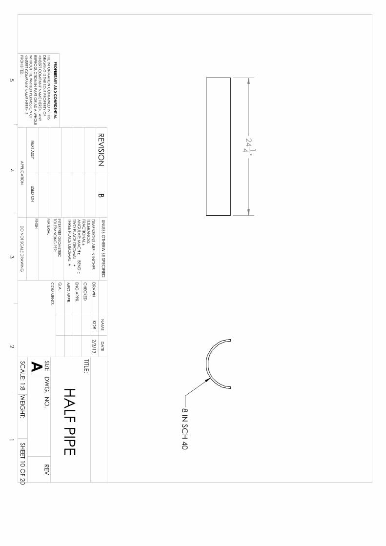
2414
"
8 IN SC
H 40
HALF PIPE
DO
NO
T SCA
LE DRA
WIN
GSHEET 10 O
F 20
2/3/13KD
R
UNLESS O
THERWISE SPEC
IFIED:
SCA
LE: 1:8W
EIGHT:
REVD
WG
. NO
.
A SIZE
TITLE:
NA
ME
DA
TE
CO
MM
ENTS:
Q.A
.
MFG
APPR.
ENG
APPR.
CHEC
KED
DRA
WN
FINISH
MA
TERIAL
INTERPRET G
EOM
ETRICTO
LERAN
CIN
G PER:
DIM
ENSIO
NS A
RE IN IN
CHES
TOLERA
NC
ES:FRA
CTIO
NA
LA
NG
ULAR: M
AC
H BEN
D
TWO
PLAC
E DEC
IMA
L THREE PLA
CE D
ECIM
AL
APPLIC
ATIO
N
USED O
NN
EXT ASSY
PROPRIETA
RY AN
D CO
NFIDEN
TIAL
THE INFO
RMA
TION
CO
NTA
INED
IN THIS
DRA
WIN
G IS THE SO
LE PROPERTY O
F<IN
SERT CO
MPA
NY N
AM
E HERE>. AN
Y REPRO
DUC
TION
IN PA
RT OR A
S A W
HOLE
WITHO
UT THE WRITTEN
PERMISSIO
N O
F<IN
SERT CO
MPA
NY N
AM
E HERE> IS PRO
HIBITED.
54
32
1
BREV
ISION

2.00
2.00
32.93
72.85°
72.85°
TS2x2x0.1875x40
DO
NO
T SCA
LE DRA
WIN
GSHEET 11 O
F 20
2/3/13KD
R
UNLESS O
THERWISE SPEC
IFIED:
SCA
LE: 1:8W
EIGHT:
REVD
WG
. NO
.
A SIZE
TITLE:
NA
ME
DA
TE
CO
MM
ENTS:
Q.A
.
MFG
APPR.
ENG
APPR.
CHEC
KED
DRA
WN
FINISH
MA
TERIAL
INTERPRET G
EOM
ETRICTO
LERAN
CIN
G PER:
DIM
ENSIO
NS A
RE IN IN
CHES
TOLERA
NC
ES:FRA
CTIO
NA
LA
NG
ULAR: M
AC
H BEN
D
TWO
PLAC
E DEC
IMA
L THREE PLA
CE D
ECIM
AL
APPLIC
ATIO
N
USED O
NN
EXT ASSY
PROPRIETA
RY AN
D CO
NFIDEN
TIAL
THE INFO
RMA
TION
CO
NTA
INED
IN THIS
DRA
WIN
G IS THE SO
LE PROPERTY O
F<IN
SERT CO
MPA
NY N
AM
E HERE>. AN
Y REPRO
DUC
TION
IN PA
RT OR A
S A W
HOLE
WITHO
UT THE WRITTEN
PERMISSIO
N O
F<IN
SERT CO
MPA
NY N
AM
E HERE> IS PRO
HIBITED.
54
32
1
BREV
ISION

1
2
1/8 1/8
ITEM N
O.
PART N
UMBER
DESC
RIPTION
QTY.
1Top Half Plate
22
STRAP
2
TOP G
IRDLE
DO
NO
T SCA
LE DRA
WIN
GSHEET 12 O
F 20
2/3/13KD
R
UNLESS O
THERWISE SPEC
IFIED:
SCA
LE: 1:8W
EIGHT:
REVD
WG
. NO
.
A SIZE
TITLE:
NA
ME
DA
TE
CO
MM
ENTS:
Q.A
.
MFG
APPR.
ENG
APPR.
CHEC
KED
DRA
WN
FINISH
MA
TERIAL
INTERPRET G
EOM
ETRICTO
LERAN
CIN
G PER:
DIM
ENSIO
NS A
RE IN IN
CHES
TOLERA
NC
ES:FRA
CTIO
NA
LA
NG
ULAR: M
AC
H BEN
D
TWO
PLAC
E DEC
IMA
L THREE PLA
CE D
ECIM
AL
APPLIC
ATIO
N
USED O
NN
EXT ASSY
PROPRIETA
RY AN
D CO
NFIDEN
TIAL
THE INFO
RMA
TION
CO
NTA
INED
IN THIS
DRA
WIN
G IS THE SO
LE PROPERTY O
F<IN
SERT CO
MPA
NY N
AM
E HERE>. AN
Y REPRO
DUC
TION
IN PA
RT OR A
S A W
HOLE
WITHO
UT THE WRITTEN
PERMISSIO
N O
F<IN
SERT CO
MPA
NY N
AM
E HERE> IS PRO
HIBITED.
54
32
1
BREV
ISION

1318
"
434
"
2916
" 2
916"
R3.99
316
" TOP HA
LF PLATE
DO
NO
T SCA
LE DRA
WIN
GSHEET 13 O
F 20
2/3/13KD
R
UNLESS O
THERWISE SPEC
IFIED:
SCA
LE: 1:4W
EIGHT:
REVD
WG
. NO
.
A SIZE
TITLE:
NA
ME
DA
TE
CO
MM
ENTS:
Q.A
.
MFG
APPR.
ENG
APPR.
CHEC
KED
DRA
WN
FINISH
MA
TERIAL
INTERPRET G
EOM
ETRICTO
LERAN
CIN
G PER:
DIM
ENSIO
NS A
RE IN IN
CHES
TOLERA
NC
ES:FRA
CTIO
NA
LA
NG
ULAR: M
AC
H BEN
D
TWO
PLAC
E DEC
IMA
L THREE PLA
CE D
ECIM
AL
APPLIC
ATIO
N
USED O
NN
EXT ASSY
PROPRIETA
RY AN
D CO
NFIDEN
TIAL
THE INFO
RMA
TION
CO
NTA
INED
IN THIS
DRA
WIN
G IS THE SO
LE PROPERTY O
F<IN
SERT CO
MPA
NY N
AM
E HERE>. AN
Y REPRO
DUC
TION
IN PA
RT OR A
S A W
HOLE
WITHO
UT THE WRITTEN
PERMISSIO
N O
F<IN
SERT CO
MPA
NY N
AM
E HERE> IS PRO
HIBITED.
54
32
1
BREV
ISION

2.25
24.25
6.00 18.25
2X 38
" THRU
TOP STRA
P
DO
NO
T SCA
LE DRA
WIN
GSHEET 14 O
F 20
2/3/13KD
R
UNLESS O
THERWISE SPEC
IFIED:
SCA
LE: 1:8W
EIGHT:
REVD
WG
. NO
.
A SIZE
TITLE:
NA
ME
DA
TE
CO
MM
ENTS:
Q.A
.
MFG
APPR.
ENG
APPR.
CHEC
KED
DRA
WN
FINISH
MA
TERIAL
INTERPRET G
EOM
ETRICTO
LERAN
CIN
G PER:
DIM
ENSIO
NS A
RE IN IN
CHES
TOLERA
NC
ES:FRA
CTIO
NA
LA
NG
ULAR: M
AC
H BEN
D
TWO
PLAC
E DEC
IMA
L THREE PLA
CE D
ECIM
AL
APPLIC
ATIO
N
USED O
NN
EXT ASSY
PROPRIETA
RY AN
D CO
NFIDEN
TIAL
THE INFO
RMA
TION
CO
NTA
INED
IN THIS
DRA
WIN
G IS THE SO
LE PROPERTY O
F<IN
SERT CO
MPA
NY N
AM
E HERE>. AN
Y REPRO
DUC
TION
IN PA
RT OR A
S A W
HOLE
WITHO
UT THE WRITTEN
PERMISSIO
N O
F<IN
SERT CO
MPA
NY N
AM
E HERE> IS PRO
HIBITED.
54
32
1
BREV
ISION

7.65 FT
56.00
506.00
112.00 168.00 224.00 253.00
280.00 336.00 392.00 448.00
12.00 30.00
60.00 78.00
1
2
ITEM N
O.
PART N
UMBER
DESC
RIPTION
QTY.
1TR6x2x3/16x180
6X2X1/8 253 IN STEEL TUBE
82
TR6x2x3/16x966X2X1/8 8 FT STEEL TUBE
103
2x2 Sq Tube10
TABLE
DO
NO
T SCA
LE DRA
WIN
GSHEET 15 O
F 20
2/3/13KD
R
UNLESS O
THERWISE SPEC
IFIED:
SCA
LE: 1:128WEIG
HT:
REVD
WG
. NO
.
A SIZE
TITLE:
NA
ME
DA
TE
CO
MM
ENTS:
Q.A
.
MFG
APPR.
ENG
APPR.
CHEC
KED
DRA
WN
FINISH
MA
TERIAL
INTERPRET G
EOM
ETRICTO
LERAN
CIN
G PER:
DIM
ENSIO
NS A
RE IN IN
CHES
TOLERA
NC
ES:FRA
CTIO
NA
LA
NG
ULAR: M
AC
H BEN
D
TWO
PLAC
E DEC
IMA
L THREE PLA
CE D
ECIM
AL
APPLIC
ATIO
N
USED O
NN
EXT ASSY
PROPRIETA
RY AN
D CO
NFIDEN
TIAL
THE INFO
RMA
TION
CO
NTA
INED
IN THIS
DRA
WIN
G IS THE SO
LE PROPERTY O
F<IN
SERT CO
MPA
NY N
AM
E HERE>. AN
Y REPRO
DUC
TION
IN PA
RT OR A
S A W
HOLE
WITHO
UT THE WRITTEN
PERMISSIO
N O
F<IN
SERT CO
MPA
NY N
AM
E HERE> IS PRO
HIBITED.
54
32
1
REVISIO
NB

4.25
4.25
1/81
TYP - 72 PLAC
ES1/8
1TYP - 72 PLA
CES
1/81-4.25
TYP - 8 PLAC
ES
TABLE - W
ELDS
DO
NO
T SCA
LE DRA
WIN
GSHEET 16 O
F 20
UNLESS O
THERWISE SPEC
IFIED:
SCA
LE: 1:48W
EIGHT:
REVD
WG
. NO
.
A SIZE
TITLE:
NA
ME
DA
TE
CO
MM
ENTS:
Q.A
.
MFG
APPR.
ENG
APPR.
CHEC
KED
DRA
WN
FINISH
MA
TERIAL
INTERPRET G
EOM
ETRICTO
LERAN
CIN
G PER:
DIM
ENSIO
NS A
RE IN IN
CHES
TOLERA
NC
ES:FRA
CTIO
NA
LA
NG
ULAR: M
AC
H BEN
D
TWO
PLAC
E DEC
IMA
L THREE PLA
CE D
ECIM
AL
APPLIC
ATIO
N
USED O
NN
EXT ASSY
PROPRIETA
RY AN
D CO
NFIDEN
TIAL
THE INFO
RMA
TION
CO
NTA
INED
IN THIS
DRA
WIN
G IS THE SO
LE PROPERTY O
F<IN
SERT CO
MPA
NY N
AM
E HERE>. AN
Y REPRO
DUC
TION
IN PA
RT OR A
S A W
HOLE
WITHO
UT THE WRITTEN
PERMISSIO
N O
F<IN
SERT CO
MPA
NY N
AM
E HERE> IS PRO
HIBITED.
54
32
1
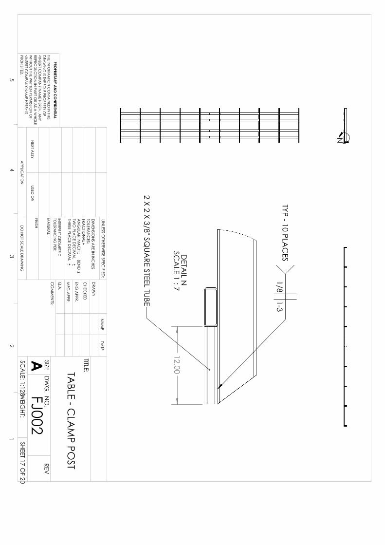
N
12.00 D
ETAIL N
SC
ALE 1 : 7
2 X 2 X 3/8" SQUA
RE STEEL TUBE
1/81-3
TYP - 10 PLAC
ES
TABLE - C
LAM
P POST
DO
NO
T SCA
LE DRA
WIN
G
FJ002SHEET 17 O
F 20
UNLESS O
THERWISE SPEC
IFIED:
SCA
LE: 1:128WEIG
HT:
REVD
WG
. NO
.
A SIZE
TITLE:
NA
ME
DA
TE
CO
MM
ENTS:
Q.A
.
MFG
APPR.
ENG
APPR.
CHEC
KED
DRA
WN
FINISH
MA
TERIAL
INTERPRET G
EOM
ETRICTO
LERAN
CIN
G PER:
DIM
ENSIO
NS A
RE IN IN
CHES
TOLERA
NC
ES:FRA
CTIO
NA
LA
NG
ULAR: M
AC
H BEN
D
TWO
PLAC
E DEC
IMA
L THREE PLA
CE D
ECIM
AL
APPLIC
ATIO
N
USED O
NN
EXT ASSY
PROPRIETA
RY AN
D CO
NFIDEN
TIAL
THE INFO
RMA
TION
CO
NTA
INED
IN THIS
DRA
WIN
G IS THE SO
LE PROPERTY O
F<IN
SERT CO
MPA
NY N
AM
E HERE>. AN
Y REPRO
DUC
TION
IN PA
RT OR A
S A W
HOLE
WITHO
UT THE WRITTEN
PERMISSIO
N O
F<IN
SERT CO
MPA
NY N
AM
E HERE> IS PRO
HIBITED.
54
32
1

24.00
7.96
6.65
BUSHING
DO
NO
T SCA
LE DRA
WIN
GSHEET 18 O
F 20
2/3/13KD
R
UNLESS O
THERWISE SPEC
IFIED:
SCA
LE: 1:8W
EIGHT:
REVD
WG
. NO
.
A SIZE
TITLE:
NA
ME
DA
TE
CO
MM
ENTS:
Q.A
.
MFG
APPR.
ENG
APPR.
CHEC
KED
DRA
WN
FINISH
MA
TERIAL
INTERPRET G
EOM
ETRICTO
LERAN
CIN
G PER:
DIM
ENSIO
NS A
RE IN IN
CHES
TOLERA
NC
ES:FRA
CTIO
NA
LA
NG
ULAR: M
AC
H BEN
D
TWO
PLAC
E DEC
IMA
L THREE PLA
CE D
ECIM
AL
APPLIC
ATIO
N
USED O
NN
EXT ASSY
PROPRIETA
RY AN
D CO
NFIDEN
TIAL
THE INFO
RMA
TION
CO
NTA
INED
IN THIS
DRA
WIN
G IS THE SO
LE PROPERTY O
F<IN
SERT CO
MPA
NY N
AM
E HERE>. AN
Y REPRO
DUC
TION
IN PA
RT OR A
S A W
HOLE
WITHO
UT THE WRITTEN
PERMISSIO
N O
F<IN
SERT CO
MPA
NY N
AM
E HERE> IS PRO
HIBITED.
54
32
1
BREV
ISION

7.50
R4.31
6.63
34.44°
6.31 3.31
316
"
GUSSET
DO
NO
T SCA
LE DRA
WIN
GSHEET 19 O
F 20
2/4/13KD
R
UNLESS O
THERWISE SPEC
IFIED:
SCA
LE: 1:4W
EIGHT:
REVD
WG
. NO
.
A SIZE
TITLE:
NA
ME
DA
TE
CO
MM
ENTS:
Q.A
.
MFG
APPR.
ENG
APPR.
CHEC
KED
DRA
WN
FINISH
MA
TERIAL
INTERPRET G
EOM
ETRICTO
LERAN
CIN
G PER:
DIM
ENSIO
NS A
RE IN IN
CHES
TOLERA
NC
ES:FRA
CTIO
NA
LA
NG
ULAR: M
AC
H BEN
D
TWO
PLAC
E DEC
IMA
L THREE PLA
CE D
ECIM
AL
APPLIC
ATIO
N
USED O
NN
EXT ASSY
PROPRIETA
RY AN
D CO
NFIDEN
TIAL
THE INFO
RMA
TION
CO
NTA
INED
IN THIS
DRA
WIN
G IS THE SO
LE PROPERTY O
F<IN
SERT CO
MPA
NY N
AM
E HERE>. AN
Y REPRO
DUC
TION
IN PA
RT OR A
S A W
HOLE
WITHO
UT THE WRITTEN
PERMISSIO
N O
F<IN
SERT CO
MPA
NY N
AM
E HERE> IS PRO
HIBITED.
54
32
1
REVISIO
NA
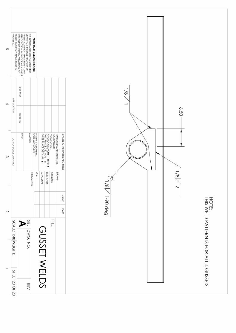
6.50 1/8
2
1/81
1/81-90 d
eg
NO
TE:THIS W
ELD PA
TTERN IS FO
R ALL 4 G
USSETS
GUSSET W
ELDS
DO
NO
T SCA
LE DRA
WIN
GSHEET 20 O
F 20
UNLESS O
THERWISE SPEC
IFIED:
SCA
LE: 1:48W
EIGHT:
REVD
WG
. NO
.
A SIZE
TITLE:
NA
ME
DA
TE
CO
MM
ENTS:
Q.A
.
MFG
APPR.
ENG
APPR.
CHEC
KED
DRA
WN
FINISH
MA
TERIAL
INTERPRET G
EOM
ETRICTO
LERAN
CIN
G PER:
DIM
ENSIO
NS A
RE IN IN
CHES
TOLERA
NC
ES:FRA
CTIO
NA
LA
NG
ULAR: M
AC
H BEN
D
TWO
PLAC
E DEC
IMA
L THREE PLA
CE D
ECIM
AL
APPLIC
ATIO
N
USED O
NN
EXT ASSY
PROPRIETA
RY AN
D CO
NFIDEN
TIAL
THE INFO
RMA
TION
CO
NTA
INED
IN THIS
DRA
WIN
G IS THE SO
LE PROPERTY O
F<IN
SERT CO
MPA
NY N
AM
E HERE>. AN
Y REPRO
DUC
TION
IN PA
RT OR A
S A W
HOLE
WITHO
UT THE WRITTEN
PERMISSIO
N O
F<IN
SERT CO
MPA
NY N
AM
E HERE> IS PRO
HIBITED.
54
32
1


