Page 1
SEMINAR REPORT ON
“VACCUM LIFTER’’
Submitted by
RAJU PATIL S/o BABASAHEB
GUIDED BY
Prof. SHINDE D.V.
ME (CAD/CAM/CAE)
Submitted in partial fulfillment of the requirement for the degree of Bachelor of
Engineering (Mechanical)
Department of Mechanical Engineering
SHRI TULJA BHAVANI COLLEGE OF ENGINEERING, TULJAPUR.
Dr. BABASAHEB AMBEDKAR MARATHWADA UNIVERSITY, AURANGABAD.
Year 2015-2016
i
Page 2
CERTIFICATE
This is to certify that the seminar report entitled
“VACCUM LIFTER”
SUBMITED BY
Mr. RAJU PATIL S/o BABASAHEB
Has completed as per the requirement of
Dr. BabasahebAmbedkarMarathwada University,
in partial fulfillment of degree
B.E. (MECHANICAL)
Guide Head of Department External
(Prof. SHINDE D.V.) (Prof. DOIJODE S. N.)
Principal
(Prof. PERGAD N.D.)
Department of Mechanical Engineering
SHRI TULJA BHAVANI COLLEGE OF ENGINEERING, TULJAPUR.
Year 2015-2016.
ii
Page 3
ABSTRACT
In piping related industries pipes are lifted and placed at desired places using
various techniques like lifting them using chains anchored at either open ends
or just by wrapping the chains around circumference of the pipes. But all
these techniques require extra manpower and consume lot of time also the
huge pipes are very difficult to balance there by requiring great skill to do the
job.
One way of over coming cons associated with this conventional working
method is to use vacuum based lifting techniques. In this technique a vacuum
suction pad is placed over the pipe to be lifted. This suction pad is connected
to a vacuum pump which then creates vacuum inside the pipe cavity which is
connected to the vacuum suction pad. Thus the pipe to be lifted gets attached
to the vacuum suction pad which can be lifted by a crane to get the pipe
lifted. The pipe thus lifted can be placed then at desired place just by letting
air inside the vacuum suction pad. This technique requires no extra human
power, the crane operated can place the suction pad over the pipe and lift and
put the same at desired place. Also this technique consumes less time.
iii
Page 4
The project work includes building a scale down model of vacuum lift
machine which includes a robotic crane that can maneuver over a flat
surface. This crane has got a robotic arm to which a vacuum suction pad is
connected; to this suction pad a vacuum pipe is connected which at the end id
fixed to a vacuum pump. This vacuum pump is a centrifugal blower that
blows out air and thus creates vacuum. The entire project works on battery
power. All motors used in the project work are DC motors and are controlled
through a wired remote. In the project work small specimen of pipe is lifted
and placed using vacuum power and robotic crane device and thus working
principle is exhibited.The project model is crafted out using aluminum, steel,
MDF, DC motors, controller switches, cables, nut & bolts, screws, plastic
pipes etc.
iv
Page 5
ACKNOWLEDGEMENT
Anything and everything in the world does not made byself-creation. It
requires so many supplementary things. It also requires a many hands, many
brains and so many efforts. We have great pleasure to representing this
seminar report on,
“VACCUM LIFTER”
We are indebted to our guide Prof. SHINDE D.V. for giving us an
opportunity to work under his guidance. Like a true mentor, he motivated,
inspired and increase somewhat may interest on this topic through the entire
duration of our work. We expressour gratitude towards our department HOD
Prof. DOIJODE S.N. for his support throughout the project work.
This is to acknowledgement thanks the entire friend group who played
defining role in shaping this seminar report. Without their constant support,
guidance and assistance this seminar report would not have been completed.
Without their coordination, guidance and reviewing this task could not be
completed alone.
v
Page 6
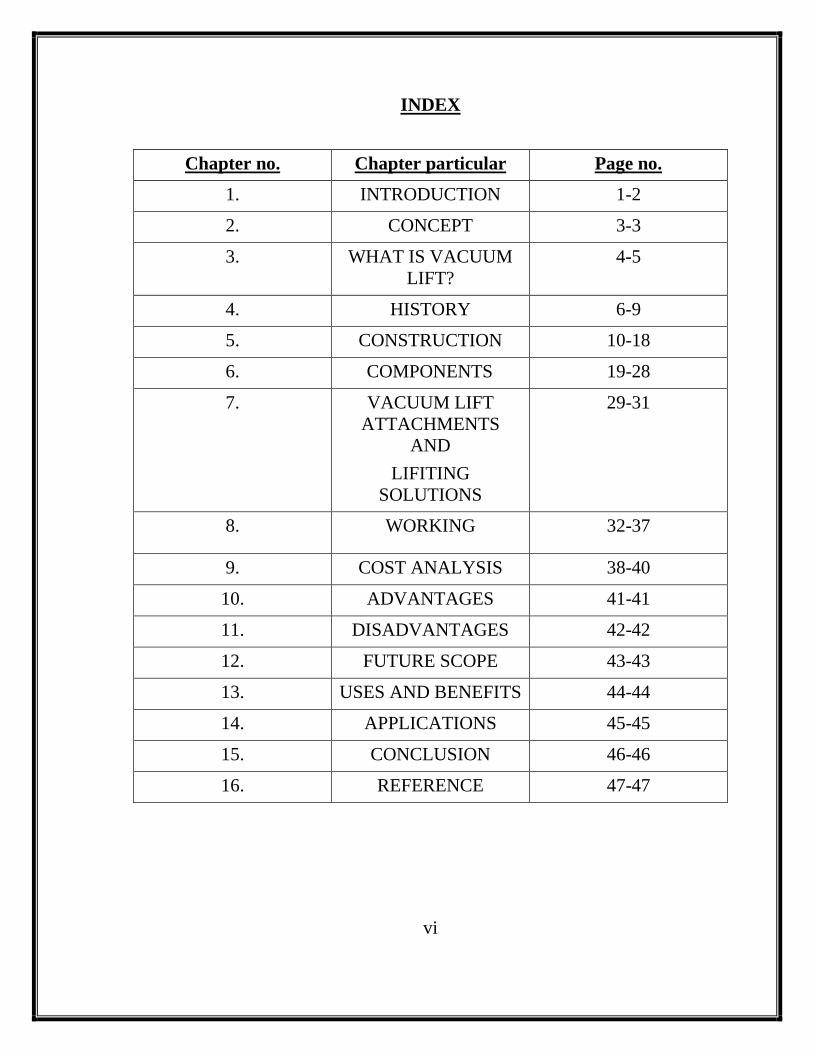
INDEX
Chapter no. Chapter particular Page no.
1. INTRODUCTION 1-2
2. CONCEPT 3-3
3. WHAT IS VACUUM
LIFT?
4-5
4. HISTORY 6-9
5. CONSTRUCTION 10-18
6. COMPONENTS 19-28
7. VACUUM LIFT
ATTACHMENTS
AND
LIFITING
SOLUTIONS
29-31
8. WORKING 32-37
9. COST ANALYSIS 38-40
10. ADVANTAGES 41-41
11. DISADVANTAGES 42-42
12. FUTURE SCOPE 43-43
13. USES AND BENEFITS 44-44
14. APPLICATIONS 45-45
15. CONCLUSION 46-46
16. REFERENCE 47-47
vi
Page 7
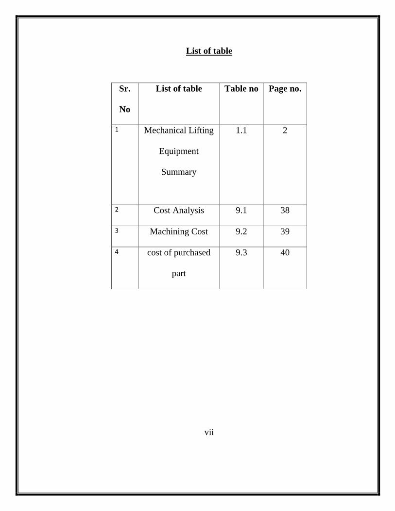
List of table
Sr.
No
List of table Table no Page no.
1 Mechanical Lifting
Equipment
Summary
1.1 2
2 Cost Analysis 9.1 38
3 Machining Cost 9.2 39
4 cost of purchased
part
9.3 40
vii
Page 8
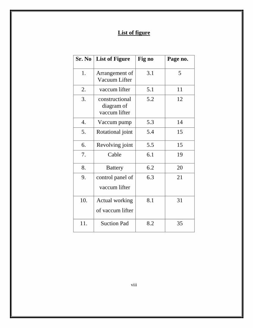
List of figure
Sr. No List of Figure Fig no Page no.
1. Arrangement of
Vacuum Lifter
3.1 5
2. vaccum lifter 5.1 11
3. constructional
diagram of
vaccum lifter
5.2 12
4. Vaccum pump 5.3 14
5. Rotational joint 5.4 15
6. Revolving joint 5.5 15
7. Cable 6.1 19
8. Battery 6.2 20
9. control panel of
vaccum lifter
6.3 21
10. Actual working
of vaccum lifter
8.1 31
11. Suction Pad 8.2 35
viii
Page 9
INTRODUCTION
In various industries lifting and pulling of something happens every
second in million count across this globe.
Much time is wasted in lifting of material with hoist or cranes etc. If
this time is reduced to minimal then whole handling of equipment can be
made more efficient.
A vacuum lifting apparatus is disclosed for lifting large, heavy objects,
wherein the lifting surface of the object deviates somewhat from a planar
configuration as in the case of manufacturing deficiencies or where the object
is of a flexible nature. A frame has opposed surfaces with a generally
peripheral deformable closed-cell resilient gasket partially secured to one
surface of the frame along the inner peripheral portions of the gasket in an
endless arrangement which defines an open chamber with the frame. A
source of reduced atmospheric pressure such as a vacuum pump, selectively
communicates with the chamber through a valve, such that positioning the
gasket member against the object and drawing a vacuum in the chamber thus
creates an atmospheric grip between the frame and the object whereby the
object may be lifted by lifting the frame. If the lifting surface is inaccurate, or
when the object flexes and assumes a curbed configuration, the partial
attachment of the gasket thus permits the gasket to decompress and to flex in
accordance with the curvature of the object, thereby maintaining the vacuum
within the chamber.
In this project an attempt is made to lower down this handling time
material by a new concept called VACUUM LIFT.
Page 10
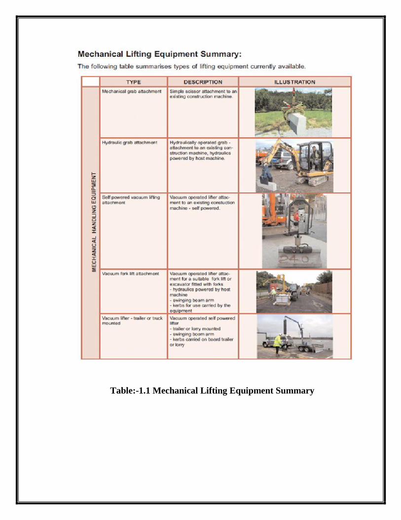
Table:-1.1 Mechanical Lifting Equipment Summary
Page 11
CONCEPT
Vacuum lift is nothing but as have suggest a technique that lifts and
places material with vacuum suction head is placed over a material to be lift
and vacuum pump stained due to vacuum created the material get stuck to
vacuum head which then can be lift by a conventional means like hoists, ram
and cranes etc.
The vacuum is created with the help of simple high speed blower type
pump. The project is carried out on a smaller / scale down version robot is
constructed which can be controlled using sensible controls that has a cam
and is made mobile using caterpillars. On this robot vacuum lift assembly is
mounted.
Page 12
WHAT IS VACUUM LIFT?
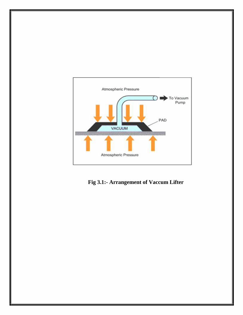
In fact everything on Planet Earth is resisting a force of 1 atmosphere
(101.3 Kpa.) at sea level. This means that a force of 101.3 KN is acting on
an area of 1 square meter. This constant energy force provided by nature is
utilized by Kilner Vacuum lifting devices. The power of vacuum is
harnessed by using specially designed vacuum pads to grip the load.
Vacuum pads can be used individually or in multiples to suit the lifting
operation and can be built into special lifting frames called Vacuum Beams.
These beams are suspended from overhead lifting gear, hoists, fork lift trucks
or built into special purpose vacuum transfer machines.
Another type of vacuum lifting device uses vacuum to lift and grip the
article or load, eliminating the need for a conventional hoist. This equipment
was specially designed for manual handling applications and is called
'LIFTMATE'. See manual handling in our product area.
Page 13
Fig 3.1:- Arrangement of Vaccum Lifter
Page 14
HISTORY
A vacuum tube lift device and a method for movement of a load by
means of a vacuum tube lift device FIFELD OF THE INVENTION THE
present invention relates to a vacuum tube lift device.
Background of the Invention and Prior Art:
Conventional vacuum tube lift devices have a flexible, vertically
disposed lifting tube, being suspended at its upper end and connected to a
vacuum source for regulating the pressure in the lifting tube. Some kind of
lifting attachment can be a book or a suction cup of the like which can be
coupled to a load which is to be lifted.
Further, the lifting tube is extendable and retractable, i.e. the lifting
tube can be compressed and extended in its longitudinal direction
(vertically). Accordingly, the lifting tube can be maneuvered by means of the
vacuum source so that the tube is compressed along is its point of suspension,
and the tube is extended when lowering the object. For this purpose the
lifting tube usually is constituted of a wire frame in the form of a helical
spring usually called a helical frame, and a cover of a substantially airtight,
flexible material enclosing the frame.
In one type of vacuum tube lift devices the lifting tube is provided with a
lifting attachment in the form of a suction foot, utilizing the vacuum in the
lifting tube for suctioning onto an object, which is to be lifted. Such a lifting
device has the advantage that an object, which is to be lifted, can be attached
to and released from, respectively, the lifting tube in a simple and reliable
way by means of regulating the pressure inside the lifting tube and the
suction foot.
Page 15
Regardless of the selection of lifting attachment, however the above
described vacuum tube lift device has the disadvantage that it has a large
installation height in relation to the lifting height capacity the lifting tube can
be compressed to a smallest possible length. The length of the lifting tube in
a state of maximum compression length, and the desired effective lifting
height substantially make up the total instillation height of the lifting device.
The relatively large compressed length, usually amounting to approx .25-
30of the installation height implies that a lifting device of the type in
question cannot be used in many spaces having a ceiling height, which is too
low in relation to the desired lifting height capacity
There is another type of vacuum tube lift devices in which the lifting
tube instead is arranged horizontally and is connected to additional vertical
component in order to take care of the vertical lifting movement. This
additional component can be a wire being provided with a hook, or the like,
for coupling to a load. In a order to achieve the vertical movement, the wire
is arranged to travel over a pulley.
Such a device, however, has the disadvantage that it instead occupies a
large space in the horizontally plane, as the entire length of the lifting tube
has to be oriented horizontally. This limits the possibility to get the desired
working areas in the horizontal plane, since the long lifting tube will be an
obstacle in certain positions. The lifting device becomes ungainly and slower
and less flexible to work with.
Another disadvantage with such a device is that a lifting attachment in the
form of suction foot cannot be used without special arrangements. The safety
of vacuum tube lift devices is based upon the fact the vacuum level in the
suction foot is the same as in the lifting tube.
Page 16
In this way, it is ensured that there is always a sufficient suction force
between the suction foot and the object, which is to be lifted.
In conventional vertical vacuum tube lift device, this is accomplished
by means of the suction foot being connected to the vacuum in the lifting
tube without any flow restriction between the lifting tube and the suction
foot. Therefore, the vacuum level will always be substantially same in both
the suction foot and the lifting tube.
In vacuum tube lift device having a horizontally arranged lifting tube,
the suction foot is connected to the wire and located at a relatively large
distance from the lifting tube, implying on one hand that relatively long
vacuum lines are required between the suction foot and the lifting tube and
on the other hand, that a time delay is created before the vacuum in the lifting
tube and the vacuum in the suction foot have assume the same level. In
certain cases, the vacuum level never assumes the same level, e.g. when
‘leaking’ goods are lifted. In that case, the flow restrictions between the
suction foot and the lifting tube being caused by the pressure drop of the
vacuum lines, results in vacuum level in the suction foot always being lower
than in the lifting tube. Since the air leaking reaches the suction foot before it
reaches the lifting tube via the vacuum lines. The result of forgoing can be
that suction force in the suction foot becomes too low in relation to the lifting
force so that suction foot come loose from the goods which are to be lifted.
In order to solve the problem with the vacuum level which is too low
in the suction foot the device can be provided with a valve arrangement, by
means of which vacuum level in the suction foot increase before it is
increased in the lifting tube and reduced in the suction foot, respectively.
Page 17
This design however, is relatively complicated in comparison to a
conventional vertical vacuum tube lift device the reason for this is the long
vacuum lines which bring about the flow restrictions, said flow restrictions in
its turn delaying the vacuum level from assuming the same value in the entire
system.
Page 18
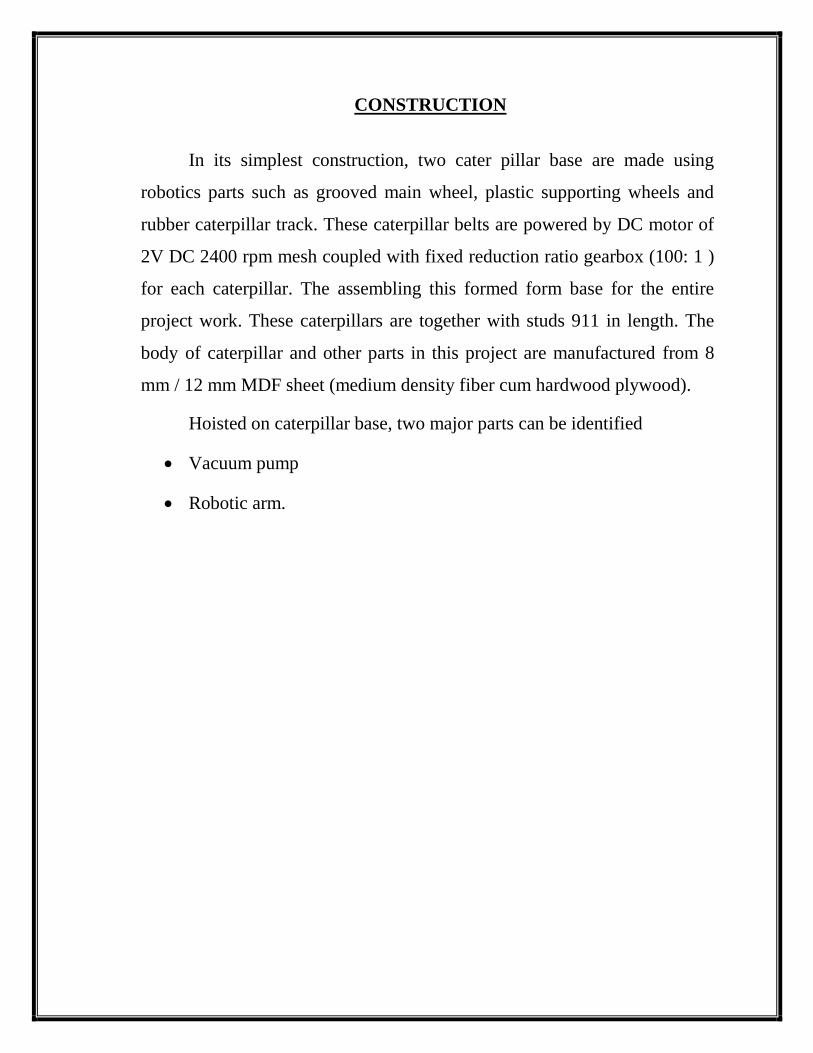
CONSTRUCTION
In its simplest construction, two cater pillar base are made using
robotics parts such as grooved main wheel, plastic supporting wheels and
rubber caterpillar track. These caterpillar belts are powered by DC motor of
2V DC 2400 rpm mesh coupled with fixed reduction ratio gearbox (100: 1 )
for each caterpillar. The assembling this formed form base for the entire
project work. These caterpillars are together with studs 911 in length. The
body of caterpillar and other parts in this project are manufactured from 8
mm / 12 mm MDF sheet (medium density fiber cum hardwood plywood).
Hoisted on caterpillar base, two major parts can be identified
Vacuum pump
Robotic arm.
Page 19
Fig 5.1:-vaccum lifter
Page 20
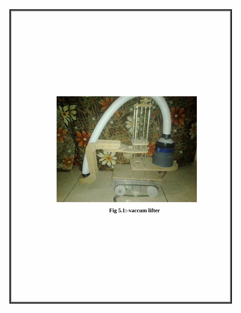
Fig 5.2:- constructional diagram of vaccum lifter
Page 21
1. Vacuum Pump:
Let us see the construction of Vacuum pump in detail - The vacuum
pump consists of a high speed 4000 rpm @ 12 V DC motor coupled directly
with a simple blower, fan blade. The whole assembly in of high density
PVC. 3" end in further reduced to 0.5" and tube is fitted having length
approximately'. The other end of tube is fixed to the arm end with vacuum
suction head which is approximately 0.5" x 211 x 0.5" in size and whole
counter are made in such a way to fit profile of that of a 211 pipe. The-
vacuum pump motor is made run a 12V DC 5 amp, so as to work with full
fledge.
Page 22
Fig 5.3:- Vacuum Pump
Page 23
2. Robotic Arm:
It is constructed from MDF, Studs, motor, gear boxes, pulleys, Belts,
ropes, etc. In all arm made is moved through five directions, the first one is
vertical having total travel of about 8`which is managed using lead screw
arrangements. The second one is circular motion which enables arm to move
through using belt and pulley arrangement. The fifth motion is swing
motion that can be managed through with an arm mounted on motor
shaft directly. The motion to every mechanism is given using a reduction
gear box meshed with DC motor.
For controlling a robot a control panel is made that encorporates
various switch to make each motor on and off the switch used for this
operation are push on type button except the vacuum pump motor each
motor revolve in reversible direction i.e. clockwise and anticlockwise using
six pins toggle switch for supplying power to each rotor a power supply is
managed.
1) Joints and Links:
A joint of an industrial robot is similar to a joint in the human body. It
provides relative motion between two parts of the body. Each joint or axis as
it is sometimes called provides the robot with a so-called degree-of-freedom
(d.o.f.) of motion. In nearly all cases, only one degree-of-freedom is
associated with a joint. Robots are often classified according to the total
number of degree-of freedom they possess. Connected to each joint are two
links, an input link and an output link. Links are the rigid components of the
robot manipulator. The purpose of the joint is to provide controlled relative
movement between the input link and the output link.
Page 24
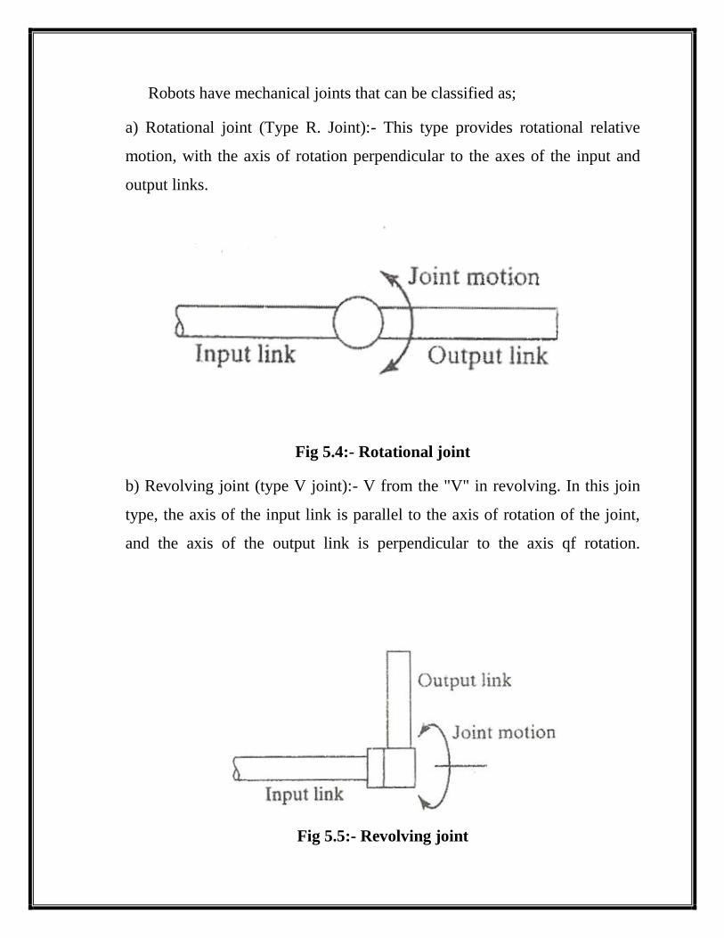
Robots have mechanical joints that can be classified as;
a) Rotational joint (Type R. Joint):- This type provides rotational relative
motion, with the axis of rotation perpendicular to the axes of the input and
output links.
Fig 5.4:- Rotational joint
b) Revolving joint (type V joint):- V from the "V" in revolving. In this join
type, the axis of the input link is parallel to the axis of rotation of the joint,
and the axis of the output link is perpendicular to the axis qf rotation.
Fig 5.5:- Revolving joint
Page 25
2)Body-and-Arm Configurations:
Given the five types of joints defined above, there are 5 x 5 x 5 = 125
different combinations of joints that can be used to design the body- and-
arm assembly for a three-degree-of-freedom robot manipulator. In addition,
there are design variations within the individual joint types (e.g., physical
size of the joint and range of motion). It is somewhat remarkable, therefore,
that there are only five basic configurations commonly available in
commercial industrial robots. These configurations are;
a) Jointed-Arm Robot :
This robot manipulator has the general configuration of a human arm.
the jointed arm consists of a vertical column that swivels about the base
using a T joint. At the top of the column is a shoulder joint (shown as an R
joint in our figure), whose output link connects to an elbow joint (another R
Joint).
Other part of robot is arm, which is constructed from MDF (medium density
fiber cum hardwood plywood), studs, motors, gearboxes, pulleys, belts,
ropes etc. In all the arm made is move through five degree or directions.
The first one is vertical having total travel of about 8' which is
managed by lead screw arrangement. The motor with reduction gearbox
(100 : 1) are attached vertically above column.
The second motor mounted on vertical column and through pulley and
belt arrangement moves the arm in circular motion. This motion enables to
arm move through 180°.
Page 26
All and every motion on mechanism given by using a constant mesh
compound dear train gearbox with reduction ratio (100 : 1). It is for provide
accuracy and to increase torque and load bearing capacity by retarding speed
of motor. All motors are DC motors directly mesh with gearbox.
For controlling a robot a control panel is made that incorporated
various switches to make each motor .ON and OFF. The switches used for
this operations are 'Push on' type buttons except the vacuum pump motor.
Each motor are made to work in reversible direction i.e. clockwise and
anticlockwise using 'Fix pin toggle switch'. For supply is managed.
Page 27
COMPONENTS
1) Motor :
The motors used in this project are permanent magnet type, DC
motor. They all are non regulated and are of two voltage type - 2V DC and
9V DC. Both types of motors are 2400 rpm motors at their relative
corresponding pick voltage value.
2) Pulley:
It is made up of 8 mm thick MDF sheet which is freely hinged on
vertical nut and bolt arrangement to supporting structure which move relative
to lead screw and nut arrangement.
3) MDF:
MDF is short form medium density fiber cum hardwood plywood.
Two types of MDF sheets are used one is 8 mm thick and other is 12 mm
thick. This is used for maximum body work. MDF sheet having high bearing
load capacity and also it is light in weight. It provides smooth finishing and
cut easily by cutting operations.
4) Studs:
Standard number stud is used having 5 mm diameter and 9" length
made up of steel.
Page 28
5) Lead Screw:
Lead screw having 5 mm diameter and 6" length lead screw and
operated circular motion in vertical axis by use of motor.
6) Gear Box:
Gear box used are reduction .type with 100: 1 reduction ratio. Whereas
first and last gears are solo gears and all are duplex one.
Advantages and disadvantages of gear box:
The two main disadvantages are
You lose speed
You have added weight for the gearbox.
Advantages to using gear reduction
You bring the boot down to a manageable speed
The motor doesn't have to work as hard to spin the wheel which means
it won't draw as much current from your batteries.
Along those lines, the torque produced by the output is inversely
proportional to the amount of reduction in the gear box. Say what?
Basically, if you have a 4:1 gear box then the bot moves 1/4 as fast but
has 4 times the torque! So you can have a 120 pound = 533 N robot
with the right gearing that will push a 400 pound = 1776 N load across
the floor.
Page 29
7) Cable:
All types of cables are made from FRC cable, ribbon wire and high
ampere rating cable for vacuum pump.
Fig 6.1:- Cable
Page 30
8) Aluminum Sheet:
This is 3 mm thick aluminum sheet used generally in arms.
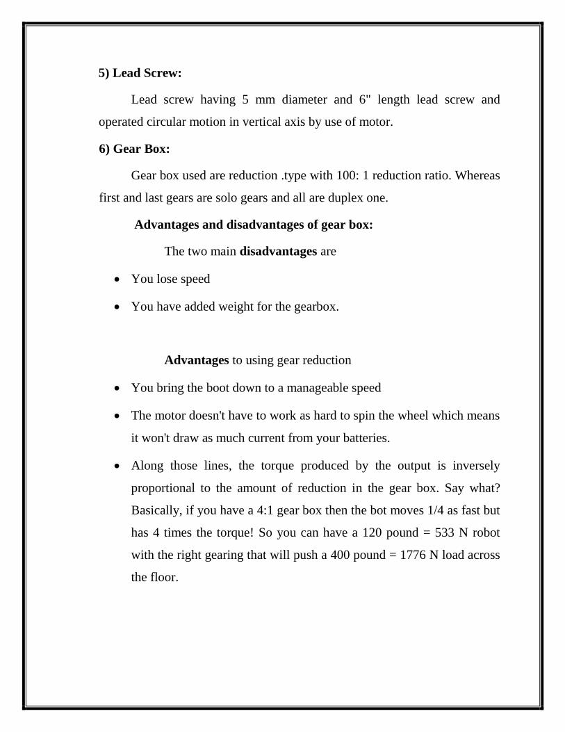
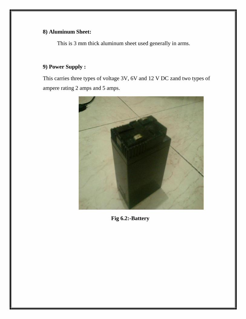
9) Power Supply :
This carries three types of voltage 3V, 6V and 12 V DC zand two types of
ampere rating 2 amps and 5 amps.
Fig 6.2:-Battery
Page 31
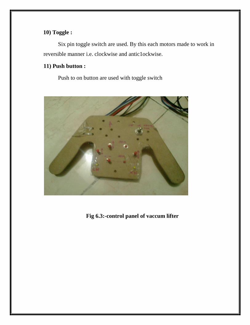
10) Toggle :
Six pin toggle switch are used. By this each motors made to work in
reversible manner i.e. clockwise and antic1ockwise.
11) Push button :
Push to on button are used with toggle switch
Fig 6.3:-control panel of vaccum lifter
Page 32
Main Component:
1. A vacuum lifter, comprising:
a. An overhead hose;
b. A housing;
c. At least one sealing plate; and.
d. At least one flexible arm having a first and a second end, the first end
attaching to an edge of the sealing plate, with a roller rotatable
attached to the second end, the flexible arm being adapted to
extending the roller connected there to a position adapted to
supporting the vacuum cleaner.
2. A flexible sealing ring located on a distal surface of each sealing plate.
3 .The sealing plate has a partially cylindrical cross section.
4. The vacuum lifter is adapted to rest and roll on the roller in response to the
vacuum holding an object being released.
5. A vacuum lifter, comprising:
a) An overhead hose;
b) A housing;
c) At least one sealing plate rigidly attached to the housing;
d) A flexible sealing ring located on a distal surface of each sealing plate;
e) A rigid arm, the arm having a first end attached to an edge of the housing
and having a second end;
Page 33
f) A roller rotatable attached to the second end of the arm, wherein a distal
extension of the sealing ring lies in a plane having a pre-selected clearance
from the roller.
6.A second roller fixed to the housing, the vacuum lifter being adapted to roll
on the two rollers.
7. A vacuum lifter, comprising : A least one sealing plate having first and
second surfaces and having a hole connecting the first surface to the second
surface; at least two arms having first and second ends, the first ends being
connected to the sealing plate, the arms projecting substantially perpendicular
to an edge of the sealing plate and substantially in the plane thereof; and at
least one roller being rotatable held between the second ends of the two arms
and having an axis of rotation substantially parallel to a line between said
second ends.
8. A flexible sealing ring having proximate and distal surfaces, the distal
surface being located on the second surface of the sealing plate.
9. A portion of the roller extends between the second surface of the sealing
plate and the distal surface of the sealing ring.
10. The roller has a pre-selected clearance with the second surface of the
sealing plate.
11. The arms are flexible and adapted to extending the roller more distal to
the second surface of the sealing plate than the sealing ring.
Page 34
12. The second surface of the sealing plate is substantially flat.
13. At least two additional arms having third and fourth ends, and projecting
substantially perpendicular to a second edge of sealing plate and substantially
in the plane of the sealing plate, the third ends being connected to the sealing
plate; and at least one additional roller being rotatable held between the
fourth ends of the two additional arms and having an axis of rotation
substantially parallel to a line drawn between said fourth ends.
14 The axis of rotation of the additional roller is substantially parallel to the
axis of rotation of the at least one roller.
15. A housing having at least one airtight passage between a first and a
second port thereof.
16. a) An overhead hose having first and second ends, the first end being
hermetically attached to the first port; and
b) At least one secondary hose having third and fourth ends, the third end
connecting to the second port and the fourth end connecting to an edge of the
hole, the edge being located on the first surface of the sealing plate, the
secondary hose for completing an airtight conduit between a second surface
of the sealing plate and the second end of the overhead hose.
17 a) A second sealing plate rigidly attached to the housing and having a
hole between third and fourth surfaces thereof; and
Page 35
b) A second secondary hose having fifth and sixth ends, the fifth end
connecting to the second port and the sixth end connecting to the edge of the
hole along the third surface of the second sealing plate, the second secondary
hose for completing an airtight conduit between the fourth surface of the
second sealing plate and the second end of the overhead hose said conduit
also open to the first secondary hose.
18. A sealing ring attached to the second surface of the sealing plate, the
sealing ring adapted to form an airtight seal between the second surface of
the sealing plate and the surface of the object responsive to being compressed
there between.
19. The second surface of the sealing plate has a partially cylindrical cross
section.
20. A vacuum lifter adapted to lifting an object, comprising:
a) A housing having at least one airtight passage between a first and a second
port thereof;
b) At least one sealing plate rigidly attached to the housing and having a hole
between first and second surfaces thereof; and
c) At least one roller rotatable attached to the vacuum lifter; wherein the
roller rotatable attaches to an edge of the sealing plate.
Page 36
21.An overhead hose having first and second ends, the first end being
hermetically attached to the first port; and at least one secondary hose having
third and fourth ends, the third end connecting to the second port and the
fourth end connecting to an edge of the hole, the edge being located on the
first surface of the sealing plate, the secondary hose for completing an
airtight conduit between a second surface of the sealing plate and the second
end of the overhead hose.
22 A sealing ring attached to the second surface of the sealing plate, the
sealing ring adapted to form an airtight seal between the second surface of
the sealing plate and the surface of the object responsive to being compressed
there between.
Page 37
VACUUM LIFT ATTACHMENTS AND
LIFITING SOLUTIONS
1. VACCUM LIFTER Lifting Attachments
Forklifts
Pay loaders
Excavators
Cranes, Jibs, Swivels, Gantries, Below-the-Hook,
Manipulators
Lorries
Your imagination is its only constraint.
2. VACCUM LIFTER the New Generation of lifting Attachments:
It is vacuum operated.
It requires no electrical or hydraulic connection to the working
machine.
It is mounted and dismantled from the forklift in minutes.
It can rotate or tilt the drum, plate or pipe 90° or 180°.
It complies with the strictest safety requirements.
The lifts drums, plates or pipes from all positions - vertically and
horizontally.
It uses virtually no electrical current and is battery powered.
It increases your production capacity rapidly and safely.
Page 38
It is cleanly operates with no hydraulic fluid and is environmentally
friendly.
3. VACCUM LIFTER the New Generation of Forklift
Attachments:
Decreases cargo damage and helps maintain the efficiency of your
machinery.
Fastens to the forklift by a simple system of bolts and chains.
Handles glass, steel sheeting and slabs, stone, plastics and wooden
products.
4. VACCUM LIFTER is delivered with CE sign for European
customers.
Curved Suction Pads Lift:
Drums : steel or plastic
Concrete pipes
Dense plastic pipes
Steel Pipes
Curved or rolled steel
Page 39
Straight Suction Pads Lift:
Glass with or without framing
Metal plates: Stainless, Carbon, Aluminium, Duplex, HRAP.
Blocks of stone: slate, granite, marble.
Plastic plates
Wooden products: plates of chips.
5. VACCUM LIFTER – Is Design To Lift All Type Of Steel And
Aluminium:
Galvanized, Stainless, and Carbon Steels
Hot Rolled Annealed and Pickled
Duplex Stainless
Hot Rolled Pickled Oiled
All types Aluminium
All types Stainless
All Stainless finishes
Page 40
WORKING
With the help of control panel the arm of this vacuum lift rob at is
made to get fixed over the object to be lift by making various combination of
toggle switches and moving arm with the help of push button.
Once the arm is over the material, the material to be lift the vacuum
pump made on as these objects lift. Again object is placed where derived by
moving arm to desired place. The object is place required position by turn off
vacuum pump. By used of caterpillar the object or robots are moved to
different location. This made it for multipurpose material handling
equipment. Thus entire project can exhibits in its working in fewer steps
only.
Page 41
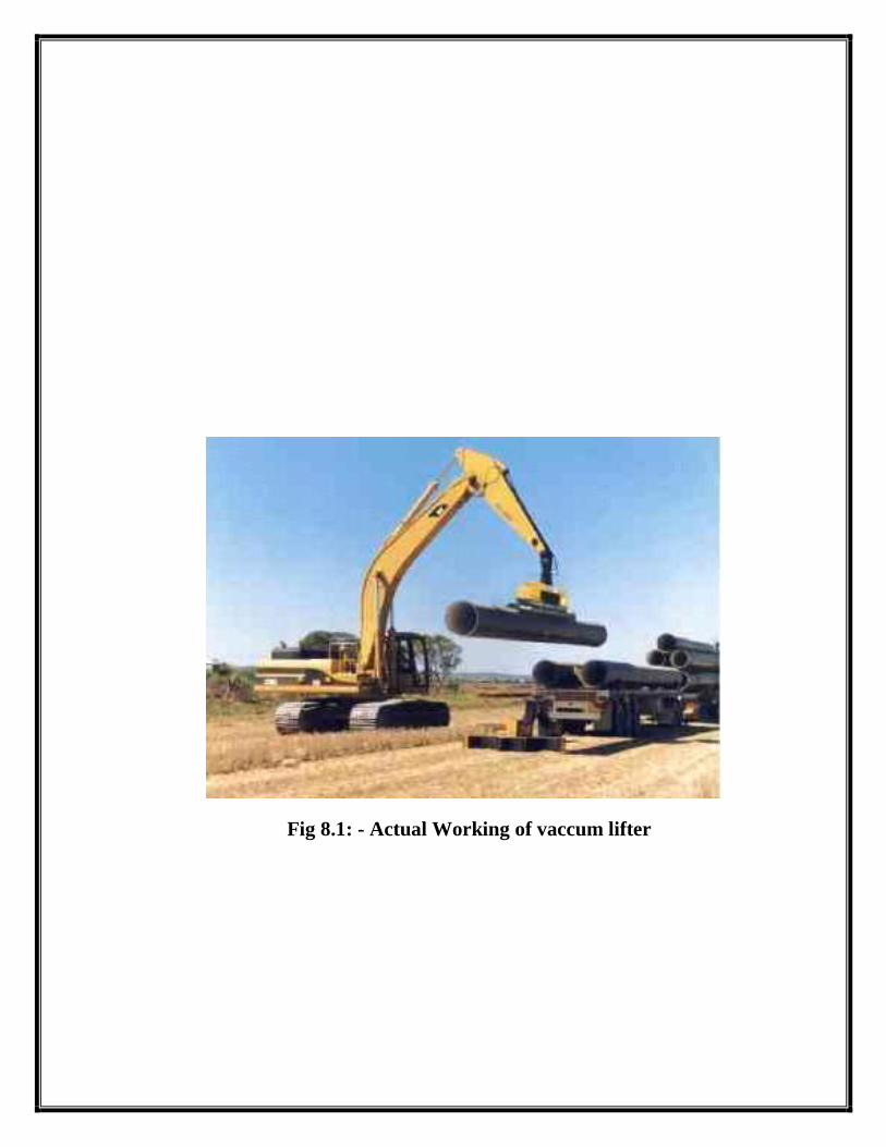
Fig 8.1: - Actual Working of vaccum lifter
Page 42
Air Suction Lifter:
The present invention concerns a air suction lifter, more precisely a
lifter for moving packages by means of the suction created inside a chamber
by a source of vacuum. In greater detail, the invention concerns a suction
lifter specially designed to be used safely and reliably on non-rigid packaging
such as cloth or paper sacks and the like. The suction lifters known at present
consist of a single suction chamber which is generally cylindrical in shape,
with one open end, across. which a part of the surface of the package is
subject to suction and deformation.
Inside the suction chamber, parallel to the open base, there is a
perforated plate, or limiter. This structure bears against and retains the area of
the upper face, subject to suction and deformation, of the package or sack to
be moved i.e. lifted, transported or deposited.
To try to conserve the high value of the low pressure inside the suction
chamber after the grip on the package has been established and maintained,
the lower edge of the outside walls of the suction chamber are fitted with air-
tight elements e.g. seals. Once the vacuum has been established and an area
of the surface of the package has been gripped, the package is moved as
desired and later released by interruption of the suction.
The main drawback of the traditional lifting device as above illustrated
is the ineffective seal obtained between the edge of the suction chamber and
the package, especially if the package is a sack (which is so in the majority of
cases).
Actually, creases or folds on the upper surface of the sack, especially
in the area involved in the suction, are formed which can extend into the area
Page 43
in contact with the aforementioned perforated plate and pass under the air-
tight seal means.
In this way the folds connect the suction chamber to the outside
atmosphere and drastically reduce the level of vacuum in the suction
chamber. Because of said reduction, the flow rate of air sucked from the
chamber has to be considerably increased to maintain the grip on the package
or sack in question. Despite this, the hold on the sack remains precarious and
it is often sufficient just to jolt the sack while it is suspended to alter
negatively the balance between the air entering the chamber and the sucked
air, thus causing the sack being lifted to fall. Further, because of the
difficulties described above, the equipment required to guarantee a sufficient
suction is so large that it can be moved only with great difficulty, thus
detracting from the flexibility required of similar devices.
Finally, because of the stated disadvantages, different sized suction chambers
are required depending on the kind of packages (sacks) to be moved.
There is then a necessity for a suction lifter which safely moves non rigid
packages, and in particular sacks of different sizes. Further, such lifter should
be operated by vacuum sources that are sufficiently small to be easily moved.
Accordingly, an object of the present invention is to solve the above
problems with the suction lifter which gives the maximum reliability in the
movement of non-rigid packages of various size and weight, and achieves a
high level of vacuum with a low suction flow rate.
Essentially, according to the invention a lifter of the suction, or
vacuum, type is provided, especially for the movement of products in non-
rigid packaging such as sacks or similar, characterized in that it comprises
two suction chambers, one of which, being smaller, is located inside the
Page 44
second chamber, both chambers being open at the end which contacts the
package to be moved, and Being provided, on the edge of said side, with air-
tight seal means on said package to be moved.
Page 45
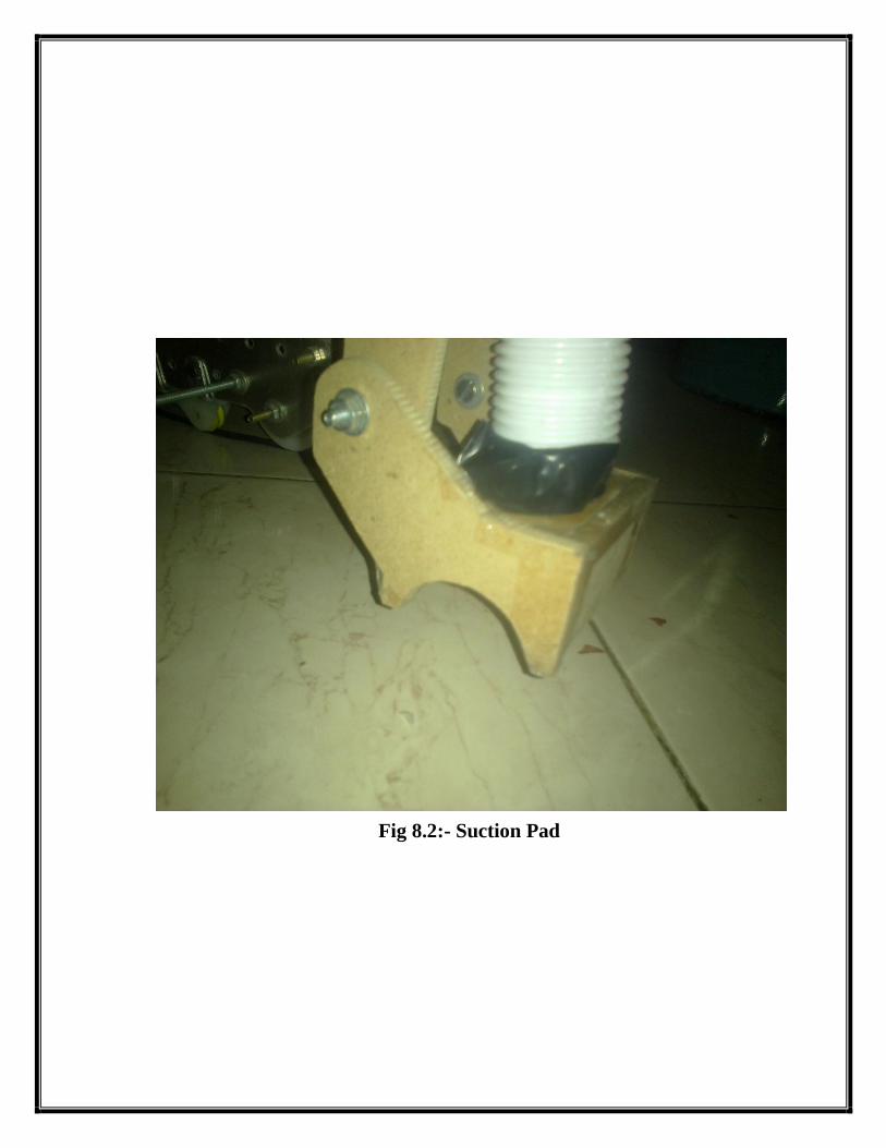
Fig 8.2:- Suction Pad
Page 46
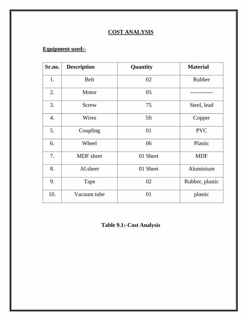
COST ANALYSIS
Equipment used:-
Sr.no. Description Quantity Material
1. Belt 02 Rubber
2. Motor 05 ------------
3. Screw 75 Steel, lead
4. Wires 5ft Copper
5. Coupling 01 PVC
6. Wheel 06 Plastic
7. MDF sheet 01 Sheet MDF
8. Al.sheet 01 Sheet Aluminium
9. Tape 02 Rubber, plastic
10. Vacuum tube 01 plastic
Table 9.1:-Cost Analysis
Page 47
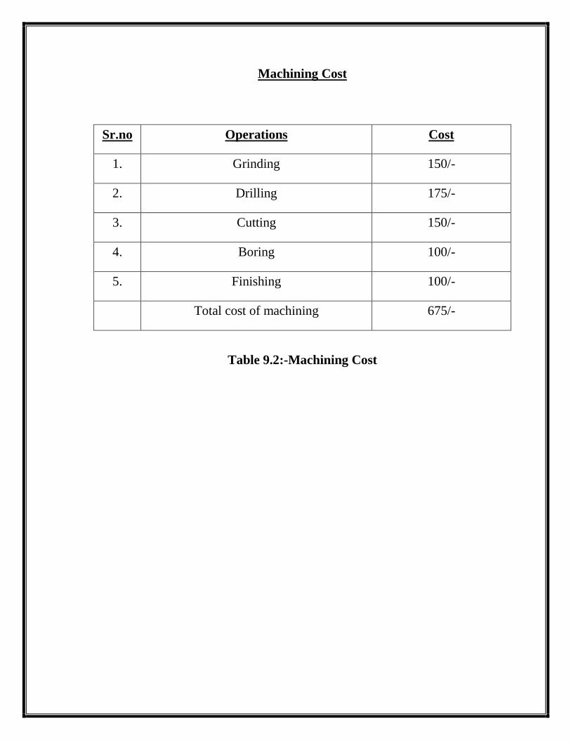
Machining Cost
Sr.no Operations Cost
1. Grinding 150/-
2. Drilling 175/-
3. Cutting 150/-
4. Boring 100/-
5. Finishing 100/-
Total cost of machining 675/-
Table 9.2:-Machining Cost
Page 48
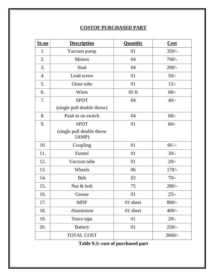
COSTOF PURCHASED PART
Sr.no Description Quantity Cost
1. Vaccum pump 01 350/-
2. Motors 04 700/-
3. Stud 04 200/-
4. Lead screw 01 50/-
5. Glass tube 01 15/-
6. Wires 05 ft 60/-
7. SPDT
(single pull double throw)
04 40/-
8. Push to on switch 04 60/-
9. SPDT
(single pull double throw
5AMP)
01 60/-
10. Coupling 01 60 /-
11. Funnel 01 30/-
12. Vaccum tube 01 20/-
13. Wheels 06 170/-
14. Belt 02 70/-
15. Nut & bolt 75 280/-
16. Grease 01 25/-
17. MDF 01 sheet 800/-
18. Aluminium 01 sheet 400/-
19. Tesco tape 01 20/-
20. Battery 01 250/-
TOTAL COST 3660/-
Table 9.3:-cost of purchased part
Page 49
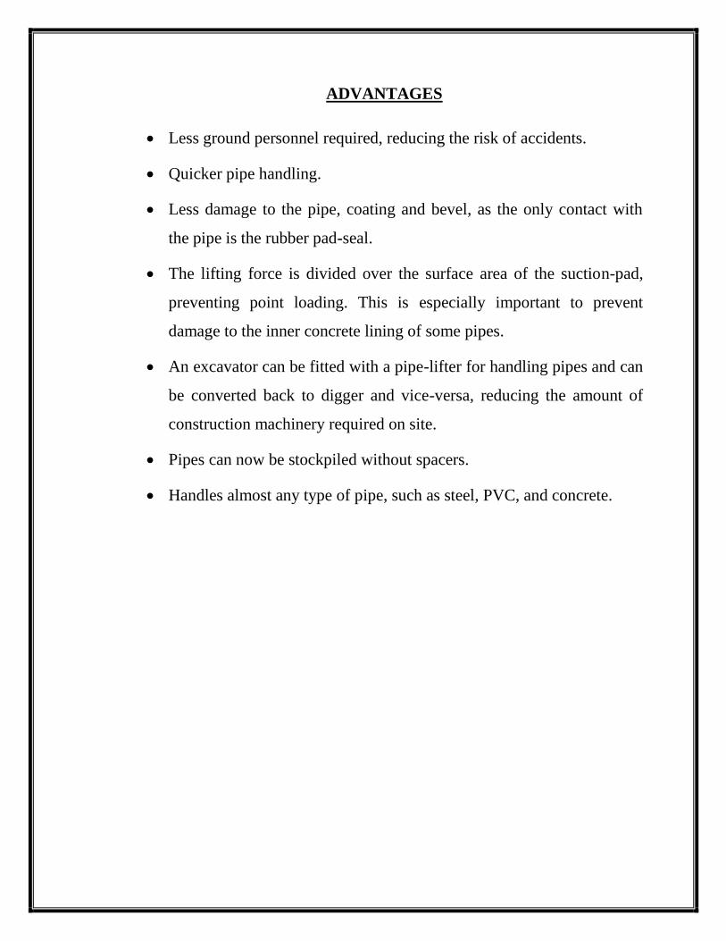
ADVANTAGES
Less ground personnel required, reducing the risk of accidents.
Quicker pipe handling.
Less damage to the pipe, coating and bevel, as the only contact with
the pipe is the rubber pad-seal.
The lifting force is divided over the surface area of the suction-pad,
preventing point loading. This is especially important to prevent
damage to the inner concrete lining of some pipes.
An excavator can be fitted with a pipe-lifter for handling pipes and can
be converted back to digger and vice-versa, reducing the amount of
construction machinery required on site.
Pipes can now be stockpiled without spacers.
Handles almost any type of pipe, such as steel, PVC, and concrete.
Page 50
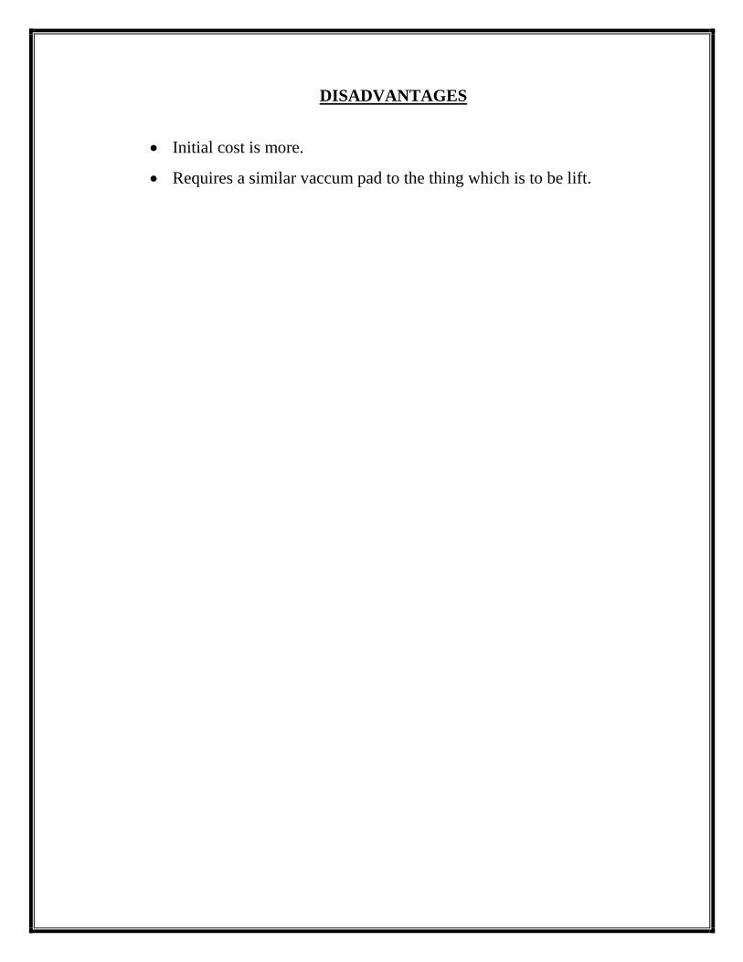
DISADVANTAGES
Initial cost is more.
Requires a similar vaccum pad to the thing which is to be lift.
Page 51
FUTURE SCOPE
This project can be improved of some fronts like the capacity of
suction pump and vacuum pump can be improved by using vane type blower
on centrifugal suction pump.
And additional suction pump can be mounted for handing, transferring
of liquid materials.
The robot can be made fully automated with predefine functionalities,
etc.
Page 52
USES AND BENEFITS
Vacuum lifting equipments can be designed to LIFT, HOLD, TURN,
TILT or ROTATE.
Almost anything can be handled such as steel, glass, concrete, plastics,
wood, aluminum, pipes, refrigerators, aircraft sections, drums, cartons,
round shaped profiled objects can be handled.
Life in safety
Gain increased productivity
Prevent back injury
Automate production
Reduce operator fatigue
Eliminate product damage
Improve working conditions
Handle delicate, hot awkward items.
Page 53
APPLICATIONS
This project can find its applications in various fields, as technique is simple
and workable. More over this technique reduces material handling time and
make tedious job easier in certain kind of material like pipe handling etc. The
probable industries where this project can be of very much use are as
follows: -
Pipe manufacturing
Pipe handling/ carrying
Glass manufacturing
Cylinder manufacturing
Manufacturing of any delicate items
General purpose manufacturing
Chemical plants
Warehouses
Logistics
Ship Building
Assembly of big parts such as Aircrafts and space ship
industries
Any manufacturing plants where isolation is required / foreign
interference is avoided.
Page 54
CONCLUSION
The project work done displaced results as expected with its immense
capabilities it may be said that this type of device may prove to be popular
material handling devices.
In Indian subcontinent this device may also be popular and it makes the
whole procedure of material handling efficient and as Indian economy is
booming, this may give a kind of beverage to implementation of such kind of
efficient device.
Page 55
REFERENCE
1. Hydraulics & Pneumatics – A technicians & engineering guide – Andrew
Parr- Jaico publishing house
2. Hydraulics and pneumatics, taraporwala publication
3. Industrial fluid power, C.P.Murgudkar, Nirali publication
4. Industrial fluid power, Dinesh V.Lohar tech max publication,
5. Pneumatic systems principles & maintenance S.R. Mujumdar, M.C.
Grawhilll
6. www.google.com
7. www.wikipedia.com
8. www.youtube.com