Department of Mechanical Engineering FACULTY OF ENGINEERING AND DESIGN FINAL YEAR MEng PROJECT Reprap Colour Mixing Project James Corbett 1 st May 2012 “I certify that I have read and understood the entry in the Student Handbook for the Department of Mechanical Engineering on Cheating and Plagiarism and that all material in this assignment is my own work, except where I have indicated with appropriate references. I agree that, in line with Regulation 15.3(e), if requested I will submit an electronic copy of this work for submission to a Plagiarism Detection Service for quality assurance purposes” Author’s signature: Supervisor: Adrian Bowyer Assessor: Andrew Dent
Transcript
Department of Mechanical Engineering
FACULTY OF ENGINEERING AND DESIGN
FINAL YEAR MEng PROJECT
Reprap Colour Mixing Project
James Corbett
1st May 2012
“I certify that I have read and understood the entry in the Student Handbook for the
Department of Mechanical Engineering on Cheating and Plagiarism and that all material
in this assignment is my own work, except where I have indicated with appropriate
references. I agree that, in line with Regulation 15.3(e), if requested I will submit an
electronic copy of this work for submission to a Plagiarism Detection Service for quality
assurance purposes”
Author’s signature:
Supervisor: Adrian Bowyer
Assessor: Andrew Dent
RepRap Colour Mixing James Corbett
Page | 2
Abstract:
With recent technological advances the cost of 3D printing has been driven down to
make the technology widely available for home users and projects such as RepRap have
become much more widespread. RepRap is an open source project started by Adrian Bowyer
of Bath University in 2005 which was designed around the ideal of creating a low cost home
printer that could self replicate a larger proportion of its own parts and is the only current
project of its type. The printing process uses a fused filament fabrication method which
melts a strand of plastic which is deposited in fine layers to build up a 3D object.
The current models of printers are rather limited to using the plastics that can be bought
from a supplier so a nozzle has been designed and developed in this report to enable the
home user to print in any colour from only having to purchase a few colours. Eventually
when this nozzle is fully developed it could be used for advanced engineering component
manufacture by using hard and soft plastics.
This report concentrates on developing the mixing properties of the nozzle to a high
standard of mixing of plastics and the final design incorporates an active mixing system using
a hex bar to generate the necessary shear in the viscous plastic to result in homogeneous
mixing.
Following this design, research should continue into its performance and development
of the software and firmware should be carried out to further implement the nozzle into the
RepRap design. Following the electronics being adapted to gain full independent control of
each filament, a colour space map can be calibrated for use with the machine to make
printing any colour possible.
RepRap Colour Mixing James Corbett
Page | 3
Acknowledgements:
I would like to thank the following people that without their help the project would have
been much more of a struggle to complete;
Dr Adrian Bowyer – for his inspiration, continuous encouragement, helpful advice and
support throughout the project.
Rhys Jones – for his unending technical support, ideas and advice with the project and
my personal machine build which both would have been significantly slower and more
painful without his help.
David Corbett, my father – for the use of his machines and workshop most weekends
until unearthly hours in the morning to produce the nozzles and complex inserts, also for his
help with providing suggestions and ideas for new designs.
Dr Andrew Dent – for his advice and help with new and existing ideas.
Submission Notes
This report concentrates on the specific design of the new nozzle where engineering
drawings can be found in the Appendix and fine details about the specific mounting to the
machine are omitted for the reason that this is very custom part of design and will vary
wildly from machine to machine.
Final Word Count : 14.884 excluding Headings and Appendices
Finally the firmware of the machine will need modification from the single extruder
command (E in the G-code see Appendix for G-code commands). Initially it is thought that 6
separate filaments may be required (Cyan, Magenta, Yellow, Black, White and Clear/Water
Soluble/Soft Filament) which will need 6 commands. For example A, B, C, D, J and K could be
used as commands (E is already standard control as is G & H, see Appendix) for each
individual filament drive but the firmware would have to check that a sum of all 6 drives
equate to that expected of E as if the machine were printing with a single filament.
The standard layout of G-code for the RepRap machine, instead of E, with the new extruder head the code will have A, B, C, D, J and K to control each filament and E will remain but will control all four filaments simultaneously [22].
Extruder Length
X & Y
Co-ordinates
Interpolation
Command
Line number
RepRap Colour Mixing James Corbett
Page | 30
4.5. Static Mixing Nozzles
4.5.1. Glue Mixing Nozzles
There is a vast supply of glue mixing nozzles available
which are used for mixing two part glues/epoxy resins,
this saves the messy process of stirring the compound
manually and also means that only the correct volume of
glue is used, thus minimising waste of the expensive
compounds. These types of nozzle use complicated
moulded plastic inserts within a (generally clear) outer
shell, from forcing the two separate glue components
through this ‘maze’ large amounts of shear are created within the viscous liquid causing
mixing to occur.
The glues used in these nozzles have a relatively high viscosity which would be similar if
not higher to that of molten plastic during printing, this means that for a mixing nozzle to
work well a similar amount of shear needs to be created within the mixing extruder nozzle as
a two part glue mixing nozzle.
Figure 4-12 - Alternating Helical Two Part Glue Mixing Nozzle [25]
Figure 4-11 - Staggered Mixing Two Part Glue Mixing Nozzle [24]
Figure 4-10 - Epoxy Resin Mixer Sketch [23].
Overall Length Approximately 150mm
RepRap Colour Mixing James Corbett
Page | 31
These inserts would be ideal for application in a plastic extrusion nozzle except for the
fact they are manufactured from plastics which would have a similar melting point or a glass
transition temperature to that of the operating temperature of the extruder nozzle. These
inserts are moulded as the shapes are very complicated and near impossible to machine,
therefore manufacturing them from a metal would be very difficult and costly.
4.5.2. Injection Moulding Mixing Nozzles
In Injection moulding there are many static mixing nozzles available used for filtering and
homogeneous mixing of a plastics during moulding. The designs of the filtering/mixing
elements vary dramatically across a large range of geometries, this suggests that there is no
real optimum design for general use in mixing and that some designs are favourable for
different purposes in the industry.
PPE Linear Edge Melt Filter Nozzle [26]
The relatively simple geometry of this filter nozzle (figure 4-12) enables easy cleaning and
minimises the possibility of the nozzle ahead becoming blocked. The relatively large flow
area of the filter in comparison to the nozzle area induces a minimal pressure loss during
use. In addition this filter can be used to homogenise and colour disperse a mix, the mixing is
caused by the high shear regions between the insert and the casing.
Figure 4-13 - PPE Melt Filter Design Nozzle [26]
RepRap Colour Mixing James Corbett
Page | 32
The filter design consists of longitudinal passages around the circumference, half of
which are open at one end and the other half to the opposite end. The centre of the filter
insert is a slightly smaller diameter than that of the casing which allows the flow of the
plastic from the entry channels to the exit (figure 4-13). The clearance between the casing
and the ‘land’ of the filter can be reduced to increased the filter performance, which creates
more shear and better mixing properties, but this would result in an increase in pressure loss
across the filter.
Figure 4-14 - Linear Melt Edge Filter [26]
Figure 4-15 - Drawing of smallest available Filter nozzle from PPE [27]
Overall Lengths Available 5 - 12”
RepRap Colour Mixing James Corbett
Page | 33
PPE Colour Mixing Nozzle [28]
In addition to the filter nozzle, specific colour mixing nozzles are available which are
somewhat more substantial in design and manufacture. The prime purpose of these nozzles
is to create maximum shear within the plastic to ensure homogenous mixing during
prolonged use.
The nozzle design (figure 4-15) uses a series of coarse pitch (1.5”) blades which are
alternate directions (left/right hand screw) to generate the shear required for mixing. These
nozzles are available with 3-18 separate blades, all the parts are fabricated from heat
treated stainless steel for abrasion and corrosive resistance.
Figure 4-16 - Cross-section of colour mixing nozzle from PPE [28]
RepRap Colour Mixing James Corbett
Page | 34
Other Static Mixing Nozzles
Nickerson Static Mixing Nozzle [29]
Nickerson has a similar concept to PPE in having multiple short mixing elements to
ensure a high level of homogenisation in the end product and are designed to be versatile
with different types including recycled plastic, the designs are specifically designed to
eliminate ‘spots, streaks and clouds of colorant’ [29] in the end product. This high level of
homogeneous addition of colour helps to reduce the quantity of colorant used which
reduces the quantity used in industry and the improvement between a standard and the
colour mixing nozzle can be seen in figure 4-16.
Figure 4-17 - Comparison between a standard nozzle (left), the Nickerson Static Mixing Nozzle (centre) using the same machine settings and a mixing element (right)
In 1998 Robocasting made advances in ceramic deposition which enabled multiple
materials to be extruded through a single orifice. The design could handle 4 separate feeds
and contained a 3mm mixing paddle which was turned when driving two feeds
simultaneously to ensure a constant consistency throughout the deposited material. This
enabled different ceramics to be mixed in a virtually infinite number of proportions and
printed in varying gradients across a single part (figure 4-9).
Figure 4-21 - Robocasting Multi-material Head (left) and deposited graded transition between two materials (right)
This head was designed as well for some reasons that are less relevant to today’s 3D
printing such as the ability to print overhangs which are possible with FFF without support
material (up to 45°) as the plastic starts to set as soon as the material leaves the nozzle but
ceramics remain soft until after they have been dried, burnout and sintered. For any degree
of overhang to be made using ceramics, support material has to be provided or the print will
simply ‘slump’ as the material is deposited at room temperature and doesn’t increase in
viscosity after having been extruded unlike FFF. An example of this sacrificial ‘fugitive’
support material can be seen in figure 4-22.
RepRap Colour Mixing James Corbett
Page | 37
Figure 4-22 - Robocasting a kaolin slurry with a support material to demonstrate 'freeform' printing [31]
4.7. Colour Space Background
Colour space is a map of all the visible colours that can be created using a method, the
two main colour spaces used are RGB (Red Green Blue) and CMYK (Cyan Magenta Yellow Key
(black)), which are used in displays and printing respectively. Additive colour (RGB) works on
the pretence that starts with black (i.e. no light) and adds wavelengths of light to create
colours which results in white light being visible when all wavelengths are emitted.
Subtractive colours (CMYK), used in printing, uses the opposite principle (as the name
suggests) and adding all three components results in black as all light wavelengths are
absorbed. Although a representation of black can be created using three components the
extra key is used as well to produce unsaturated, deeper black tones and dark colours.
Figure 4-23 - Colour Space represented in a horseshoe shape (left) [32] and representations of RGB and CMYK (right)
[33]
RepRap Colour Mixing James Corbett
Page | 38
For this nozzle development the CMYK colour space will be used but as the FFF method
does not print onto an object (i.e. paper/blank model etc), so there will need to be 5
filaments in total being Cyan, Magenta, Yellow, Black and White to obtain the full colour
spectrum, white being a used to create lighter shades and the absence of colour. Usually in
printing white is not needed as less ink is printed onto a page to achieve a lighter shade of
colour. In the programming of the nozzle with full colour capabilities white or an additional
clear filament would have to be defined as a default to fill in where colours are not required.
The analysis of colours produced using the mixer nozzle will be using CMYK values
(although the colours will only be compared with the original filaments used) as this will be
easier to relate printing methods and when the design is fully operational the programming
of colours to print with will be using CMYK based system.
Figure 4-24 - Colour wheel showing how RGB compares with CMYK [34]
RepRap Colour Mixing James Corbett
Page | 39
5. Aims and Objectives
The primary aim of this project is to enable the use of a single nozzle to print using
multiple colours, this can be achieved by driving a single feed or multiple feeds
simultaneously and mixing.
The main objectives of the project, which will initially be tested using black and white
filaments on two feeds to the new extruder head design, are;
To investigate the mixing properties of the extruder head when two colours are
fed simultaneously into the head. For example if blue and yellow are fed into the
head either; green will be fed out of the nozzle, or if the viscosity of the plastic
within the heating head is sufficient this may prevent mixing and result in a ‘stripy’
outcome. If the latter is the case then further investigation maybe required into
encouraging the mixing of the plastics.
To investigate the performance of the mixing head to print using single colours
and alternating between different feed sources.
To investigate the proportions of input feed rates to get a desired outcome of
colour.
Investigate the method for printing colour gradients across a component.
RepRap Colour Mixing James Corbett
Page | 40
5.1. Possible Additional Work
If time prevails further investigation that may be explored might include;
Investigate the possibility of using varying property plastics in the mixing nozzle to
get desired material properties.
Investigate the possibility of using water soluble plastics (such as PVA) together
with standard used plastic (PLA) to make more complicated geometries by printing
as a solid piece before dissolving the water soluble plastic to leave the standard
plastic.
RepRap Colour Mixing James Corbett
Page | 41
6. Mixer Extruder-Head Development
6.1. Design Methodology
Considerable research has gone into RepRap and other 3DP extruder designs which have
been tested thoroughly by the online community, therefore as the performance of other
extruder drives are well known, the incorporation of as many existing designs/parts as
possible is necessary to maximise the reliability of the drive mechanism to ensure the main
variable is the new mixing nozzle. Also if existing parts and designs are used, then upgrading
existing machines will require minimal effort.
6.1.1. Extruder Design
There are many different types of extruder available for RepRap machines but it was
decided at the onset of this research to use the Bowden tube extruder (section 4.2 &
Appendix C), the main reason for this was down to the separate mounting on the machine.
As the intention is to use 4/6 extruders for the final design the available space on any X-
carriage would not be sufficient to hold these, as well as the additional weight would cause
problems with the drive causing miss stepping and compromising on print quality. Having
the motors mounted on the frame of the machine would mean the weight of the X-carriage
is reduced and the accessibility of the nozzle is increased for maintenance. Finally the
extruder heated mass should be kept to a minimum to reduce warm up times and refrain
from upgrading to a more powerful heater resistor thus keeping the energy consumption of
the machine down.
6.1.2. Material Selection
Using the information from section 4.3 it was decided to use PLA for this particular
research project as it is more common in the laboratory at the moment due to ease of
RepRap Colour Mixing James Corbett
Page | 42
supply, lower printing temperatures and pleasant smell from the extrusion process. In
addition PLA has a lower viscosity than ABS so should be more easily and readily mixed. PLA
is available in different chain lengths (hard and soft) which if mixing was possible would
mean the user could define the hardness of the printed part. Also PLA is more widely
available in a variety of colours compared to ABS so close matching plastics to CMYK can be
found for printing a full colour spectrum. Finally the renewable source of this material makes
this plastic much more appealing and its biodegradability makes it environmentally friendly.
For initial experiments it was decided to use black and white filaments only to give the
biggest possible contrast in colour so it would be easily observed whether mixing of the two
plastics had taken place.
6.1.3. Design for Manufacture
A large part of the RepRap fundamentals is Design for Manufacture, as many of the parts
as possible that cannot be RP by the machine itself and are not standard parts should be
able to be manufactured by as few tools as feasible. If possible everything should be able to
be manufactured using a lathe (basic operations if possible), a pillar drill and standard hand
tools. Other considerations that should be made while designing parts is that they should be:
simple; easy to repair/replace; economical; reliable; strong and accurate.
6.2. Method
6.2.1. Mixing Performance Testing Method
This section describes the general method for testing the mixing properties of a nozzle,
each design requires variations in the testing procedure which are outlined in more detail in
the relevant nozzle section.
RepRap Colour Mixing James Corbett
Page | 43
For testing of the nozzle, first step is to analyse the performance of the head while being
fed manually. The nozzle should be rigged up to the electronics of the machine (thermistor
and heater resistor) and ensure that the correct thermistor look up table is selected in the
firmware of the machine (Appendix H), for these experiments the firmware used will be
Sprinter. The filament drive motors for these initial trials should be wired in series with one
another, this is done for two main reasons; the first being to ensure the motors are driven at
the same rate which results in a ratio of filament 1:1; the second being to keep the load
down on the machine electronics as the motors are driven by current (if the motors are
wired in parallel the total current required is approximately doubled). The sequence for
wiring is as follows ;
1B -- black -- motor1 -- green -- black -- motor2 -- green -- 1A
2A -- red -- motor 1 -- blue -- red -- motor2 -- blue -- 2B
Connect up two PTFE feed tubes (simply threaded into the nozzle block) and blank off
any other remaining feed holes using grub screws with PTFE tape around the threads. Then
blank off the mixing chamber hole on top of the block using the appropriate thread (leaving
approximately 5mm protruding) and PTFE tape to ensure no leaking. Finally attach the PEEK
insulating block onto the protruding thread from the mixing chamber blank thread and
clamp the PEEK in a vice to hold the nozzle for heating up to temperature. Carefully feed the
filaments down the PTFE tubes taking note of how much force is required for this, the force
should be easily done by hand if tools such as pliers are required then this will most probably
result in the drive motors stalling.
Following this initial trial and assuming the force required to feed the filament into the
nozzle is not excessive, the nozzle can be mounted via the PEEK insulator onto the X-carriage
RepRap Colour Mixing James Corbett
Page | 44
of the machine then the Bowden tubes can be connected up to the drive mechanism
(Appendix C), after this is done the nozzle is ready to be use for printing. To keep the
programming to a minimal amount at this time the two separate stepper drive motors were
wired up in series (hence driven at the same speed) meaning only a ratio of 1:1 is possible,
this means that the machine retains all its other functions (X, Y, and Z axis) and printing using
this nozzle requires minimal change to the software. The slic3r settings used for this initial
print can be seen in Appendix B-3.
Initially the temperature of the nozzle used for extrusion should be set to 200°C which is
common for printing with PLA, if the mixing is not entirely sufficient trials can take place at
up to 220°C to reduce the viscosity of the plastic which should aid mixing, unfortunately this
is nearly the limit of the plastic and further increase of temperature may cause thermal
decomposition of the plastic which could induce a colour change so the ending result will be
difficult to judge.
Following this method, inserts may be made to cause extra turbulence within the mixing
chamber, these shall be made to a comfortable fit (i.e. clear of the retaining thread and
easily fitted by hand into the mixing chamber, but a good enough fit that the plastic will not
easily flow around the insert). Then the same method as above should be repeated.
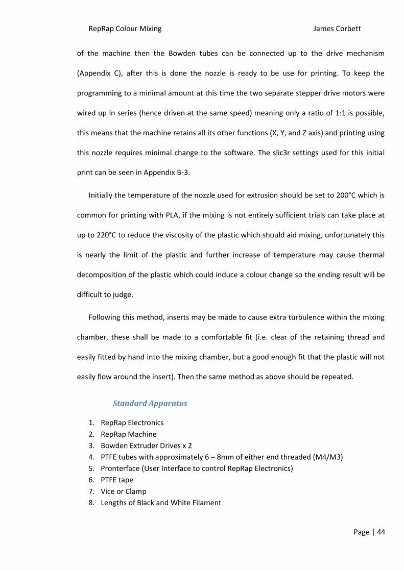
Standard Apparatus
1. RepRap Electronics
2. RepRap Machine
3. Bowden Extruder Drives x 2
4. PTFE tubes with approximately 6 – 8mm of either end threaded (M4/M3)
5. Pronterface (User Interface to control RepRap Electronics)
6. PTFE tape
7. Vice or Clamp
8. Lengths of Black and White Filament
RepRap Colour Mixing James Corbett
Page | 45
6.3. Initial Experimentation
6.3.1. Colour Mixing Trial
Summary
This short experiment was carried out to prove that the mixing of coloured PLA filament
is possible and produces expected effects (similar to mixing paint colours) and was designed
to roughly evaluate the relative pigment strengths to one another, so that when using a
mixer nozzle, the extruded filament colour should be easily predictable. This will help
identify whether both extruders are working properly during future experiments.
Introduction
Due to the limited literature found about the pigments used to colour PLA filament initial
trials were carried out to verify that the PLA plastics would mix and colours would behave as
expected (e.g. blue and yellow mix to produce green) and discover how much effort is
required to mix a small sample. Finally this trial would determine the relative strength of
pigments used in the PLA.
Apparatus and Material
1. Hotplate
2. Glass Beaker
3. Insulated Stirrer
4. Glove
5. Variety of Plastic Filament [35]
Method
1. Pre-heat the hotplate and glass beaker to just above the melting point of PLA ~150°C.
2. Pre-cut some equal lengths of two colours of PLA approximately 10mm should be ample.
3. Place two pieces (1 of each colour) of filament into the dish and allow to melt before
carefully stirring until a uniform colour is observed.
RepRap Colour Mixing James Corbett
Page | 46
4. If the one colour dominates the mix then add another piece of the opposite colour and mix.
5. Repeat step 4 until the resulting colour is a rather distinct colour between the two initial
colours.
Results and Discussion
The experiment was repeated 8 times using Faberdashery filament colours of Classic Black, Arctic
White, Fire Truck Red, Electric Blue, Lapis Blue and Mellow Yellow [35]. These colours were chosen as
they were to closest available comparison to CMYK and white from the company. The results can be
seen in the figure 6.1 for a 1:1 mix ration below.
Figure 6-1 - Mixing results from ratio of 1:1.
Further mixing and varying the mix ratios was not as successful as intended due to the
plastic melting to a lower viscosity causing adjacent colours to run and blend, despite the
Lapis Blue
Classic Black
Arctic White
Mellow Yellow
Lapis Blue Arctic White
Fire Truck Red
Mellow Yellow
Electric Blue Fire Truck Red
RepRap Colour Mixing James Corbett
Page | 47
experiment not working to a brilliant standard the results were still clear and figure 6-2
shows further mixing with respecting mix ratios. The samples were not fully mixed due to
the viscosity of the plastic, further mixing pulled extra plastic from the side hence it was
deemed acceptable to leave the ‘swirls’ in the sample.
Figure 6-2 - Mixing Results with different ratios of colour.
The mixing performed exactly as expected and produced uniformly mixed samples
(initially) with a short stirring time and some brightly coloured end products. This short
experiment proved that the two different filaments can be mixed to produce another colour
at a much lower temperature than that within the nozzle at printing temperature, thus more
viscous for this experiment, therefore the mixing within a nozzle should be feasible.
Light Blue
(1:1, Lapis Blue : White)
Orange
(4:1, Yellow : Red)
Light Yellow
(1:1, Yellow : White)
Grey
(3:1, White : Black)
Purple
(1:1,
Lapis Blue : Red)
Green
(2:1,
Yellow : Electric Blue)
Purple
(2:1, Electric Blue : Red)
Dark Maroon
(1:1, Red : Black)
RepRap Colour Mixing James Corbett
Page | 48
The relative strengths of the pigments were found to be as follows;
Strength Filament Colour
Strongest Classic Black
Fire Truck Red
Electric Blue
Lapis Blue
Mellow Yellow
Weakest Arctic White
Table 1- Relative colour pigment strengths in order (strongest at the top).
Conclusion
Progression with the mixing nozzle can now take place as this experiment has shown that
the plastics can be uniformly mixed. The relative strength of the plastic pigments have been
determined approximately so the colours to be expected from future experiments is known
which will help evaluate the level of mixing occurring within the nozzle. It is also now clear
that mixing black and white filament in a ratio 1:1 will result in a colour not very dissimilar to
that of solely black, this will make it easy to determine the level of mixing happening within
the nozzle as only a small amount of mixing will result in the white filament turning grey.
RepRap Colour Mixing James Corbett
Page | 49
6.3.2. Initial Testing of the Nozzle MkI designed by Bowyer
Introduction
It is necessary to assess the performance of the mixing nozzle without any static mixing
inserts as suggested in section 4.5. This will help identity how much extra mixing is required
to achieve the desired effect of the nozzle, the performance of the nozzle is completely
unknown and it is possible that no extra design is necessary although this outcome is very
unlikely.
This experiment can result in three separate outcomes; first being unlikely, and could be
a great impediment on the future of this idea if it is to be the case, is the force required to
drive the filaments into the nozzle is excessive which would cause the stepper motors to stall
if they were connected; the second possible outcome is that the two filaments (black and
white) will mix uniformly to produce a dark grey extruded material; finally the third and
most likely outcome is that the two filaments (black and white) will not mix and extrude out
of the nozzle to produce a stripy (‘toothpaste’) effect, half black and half white. The final
outcome may not be as undesirable as first thought as the nozzle diameter is only 0.5mm
and to the human eye the two separate strands may appear a uniform colour, but further
investigation will still be required to improve mixing quality of the nozzle.
Additional Apparatus
1. Mixing Nozzle MkI (Figure2-5 & Appendix D-1) with heater resistor and 100k bead
thermistor fire cemented in place.
2. 3mm OD (2mm ID) PTFE Tubes
3. Length of M4 threaded rod approx 12mm length and M4 nut
4. PEEK insulators (M4 internal thread)
5. M3 Grub Screws
RepRap Colour Mixing James Corbett
Page | 50
Method
Set up as in section 6.1.4, this can be seen in figure 6-3 with white filament being fed
from the left and black from the right. The mixing chamber blank is wrapped in PTFE to
create a good seal and is locked using an M4 nut to ensure the blank remains firm in place.
Figure 6-4 - Mixer nozzle mounted for printing.
Results and Discussion
The two separate filaments were easily observed in the extruded filament with a clear
distinction between the black and white filaments on either side. The extrusion forces were
Figure 6-3 - Initial set-up of mixer nozzle (left), nozzle mixing chamber plug, locking nut and PEEK insultator set-up (right).
RepRap Colour Mixing James Corbett
Page | 51
not significantly increased compared to normal extrusion therefore it was possible to rig the
nozzle up to the machine for a test print.
The first test print can be observed in figure 6-5 and produced some interesting results,
as stated above the filaments failed to mix and came out as two separate colours, in the
print this is apparent as two sides are almost completely black and two sides are white, on
the top and bottom of the print each pass of the printer can be seen with a streak of black
and white side by side.
Figure 6-5 - First mixer nozzle print with very different appearance from opposite sides
Figure 6-6 - Underside of first print, the extra shear caused between the nozzle and the print surface caused extra
shear thus better mixing qualities
The underside of the this first print was similar to the side and top, but with closer
inspection there was small evidence of mixing, this was believed to be caused by the extra
shear between the build surface and the nozzle tip, the distinction between the black and
white filaments were slightly blurred with a slight grey region between the two.
RepRap Colour Mixing James Corbett
Page | 52
Conclusion
From this initial trial is it clear that a significant amount of extra mixing is required to
reach the target of uniform colours. The extrusion forces were as per normal for a standard
nozzle and the printability with this new nozzle appeared unaffected from standard use, any
untidy edges seen in the figures could be cleaned up by more careful calibration of the
extruder steps and other settings within the Slic3r configuration file (Appendix B-3).
Figure 6-7 - MkI Nozzle print
Out of interest another print was tested and the result can be seen in figure 6-7 one side
was mostly black and the other was mostly white. It can also be observed how the colour
fades between the two. Another observation during the print was the failure of the white
filament feed which led towards the black streak in the centre of the print, initially this was
thought to be caused by the filament slipping on the hobbed bolt caused by the pressure
within the nozzle. After further inspection it was discovered that the clamping force on the
idle bearing was far too great for the filament which caused the filament to become
deformed and flattened which consequently the filament to become lodged in the PTFE tube
causing the hobbed bolt to slip on the filament, this could become a problem later if large
extrusion forces are required.
RepRap Colour Mixing James Corbett
Page | 53
6.4. Static Mixer Nozzle Development
6.4.1. MkII Nozzle Design
Introduction
Following the previous trial with the MkI mixer nozzle a similar nozzle was machined but
with a larger diameter mixing chamber, this enabled a brass insert to be placed within the
mixing chamber to cause extra turbulence. It may have been possible to fabricate an insert
for the MkI nozzle but the diameter of the chamber was very limited which would have
required precision engineering and fine tolerances, so for ease of manufacture and
experimental purposes this new nozzle was made so that inserts can be easily manufactured
to perfect the design then trials can be made to scale the insert down to reduce the size of
the final nozzle.
Figure 6-8 - MkII Brass mixing Nozzle with Mixing Chamber Brass Mixing Insert in Place
Apparatus
1. Mixing Nozzle MkII (Figure 6-8 & Appendix D-2) with heater resistor and 100k axial
thermistor in place.
2. 3mm OD (2mm ID) PTFE Tubes/4mm OD (2mm ID) PTFE Tubes
3. Length of M6 threaded rod 12mm/ Mixing Insert with M6 thread and locking nut.
4. PEEK insulators (M6 internal thread)
5. M3/M4 Grub Screws
RepRap Colour Mixing James Corbett
Page | 54
Method
This nozzle was first tested using the identical set up as with MkI to verify that the results
are similar with no insert (figure 6-9) which produced a virtually identical print as before
(figure 6-12), then repeated with four different brass inserts (figure 6-10 & Appendix E).
Figure 6-9 - Nozzle MkII set-up with blank (left) and mixing insert (right).
Figure 6-10 - Brass Inserts Tested; No.1 LH Thread Pitch-1.67mm Cut Depth-1mm (Far Left): No.2 LH Thread with Reversal to Right Hand Thread Pitch-1.67mm, Thread Depth-1.25mm (Left): No.3 Hollow Insert with 6 Holes (Ø1mm) equally spaced at 120° (Right): No.4 Hollow Insert with ridge and end blanked off (Far Right).
RepRap Colour Mixing James Corbett
Page | 55
Figure 6-11 - MkII Nozzle set up in vice for testing with mixing insert in place.
Results and Discussion
The initial testing on insert No. 1 (Figure 6-10) showed up a few problems with the set-up,
due to the reduced cross sectional within the mixing chamber, the pressure required to drive
the filament through the nozzle was greatly increased to the point that the 3mm OD PTFE
tube was forced out of the block due to the flexibility of the tube and minimal thread depth.
Before the tube was forced out of the block the end couple of millimetres of the PTFE tube
nearest the nozzle had a slight ballooning effect, this is down to the PTFE losing some rigidity
at higher temperatures. This ballooning and ‘blowing out’ from the nozzle was solved by
increasing the outer diameter of the PTFE tube to 4mm and retaining the inner diameter at
2mm. By using the larger diameter PTFE tube the volume of material is increased
approximately 2.4 times meaning the strength is more than doubled, this increase in
strength was enough to withstand the pressure in the nozzle.
After modifying the nozzle the experiment was re-attempted which saw little difference
from the original Mk1 nozzle, the two separate filaments could easily be depicted from the
extruded material. It was also noted that the force required to drive the filament was greatly
Slight ballooning
of the PTFE tube
RepRap Colour Mixing James Corbett
Page | 56
increased from the original nozzle although didn’t appear to be excessive. The nozzle was
then attached to the machine to test the print quality so a comparison can be made with
MkI.
After connecting the nozzle to the RepRap extrusions were attempted but due to the
large forces required to drive the filament the stepper motors stalled, therefore the power
was increased to the motors which subsequently caused the hobbed bolts to slip on the
filament. From these results it was deemed an unusable design so the experiment was
attempted with a second insert which incorporated a left hand thread which reversed into a
right hand thread, this reversal in thread direction was to try to induce extra shear into the
molten plastic to induce some further mixing. In addition to the thread reversal the thread
was made using a deeper cut of 1.25mm in an attempt to reduce the pressure within the
nozzle.
Using the second insert the hand feeding of filament into the nozzle force was not
significantly reduced and the mixing performance was unchanged, the same results were
yielded with the nozzle mounted on the machine with the stepper motors being unable to
drive the filament so no print was produced. This resulted in the design of the third insert
which tried an alternative method for mixing.
The third insert consisted of a hollow tube with a chamfered end which initially this was
left high from the bottom of the mixing chamber (approx 1mm gap), the hollow tube had 6 x
Ø1mm holes which the plastic would be forced through before heading down towards the
nozzle end. It was thought that forcing the filaments through a number of small diameter
holes would increase shear within the plastic inducing shear. The results can be seen in
RepRap Colour Mixing James Corbett
Page | 57
Figure 6-12, from sample No. 3 there was no real visible change in the mixing quality of the
nozzle and the prints were practically identical.
After print No. 3 was produced it was tested to see if increasing the temperature caused
any additional mixing due to the reduction in viscosity which produced sample No. 4, this
was in vain and no difference was noticed. This was thought because even though the
viscosity of the fluid is reduced the Reynolds number is still very low due to the minimal
velocity of the fluid as Reynolds number is a function of both these variables.
Figure 6-12 - Test prints from MkII nozzle; (From left to right) 2. Control Print with no insert, 3. Insert No.3 used at
200°C, 4. Insert No.3 used at 220°C, 5. Insert No. 3 used after tightening at 200°C, Insert No.4 used at 200°C.
The third insert was tested again after ensuring a seal with the bottom of the mixing
chamber was made, this would reduce the flow area towards the nozzle thus increasing the
pressure but the compromise could have paid off with the extra shear created by increasing
the velocity through the small diameter holes. This created a noticeably different print (No. 5
in figure 6-12), there was no clearly visible white filament remaining in the print, where
there had been white filament in previous prints now appeared a light grey, although the
black filament remained unchanged from previous test prints, it was hoped that the final
insert would create more mixing due to the plastic being forced through small diameter
holes twice before the nozzle, as the plastic is forced into, down and then out of the insert.
RepRap Colour Mixing James Corbett
Page | 58
The results from No. 4 insert can be seen in figure 6-12 sample No.6 which was almost
identical mixing quality to that from sample No.5, two further test prints were carried out
which consisted of a 15mm diameter cylinder with a dome top (figure 6-13).
Figure 6-13 - Test Dome Print Drawing (Left), 2/3 Black Dome Print (Top Right), 2/3 Grey Dome Print (Bottom Right).
The results were apparent from a quick observation, two prints were carried out with
exactly the same Machine settings but with the black and white filaments swapped over
between, thus changing the relative orientation of the insert. It was clear that one colour
dominated one side of each print which was reversed when the filaments were swapped.
Figure 6-14 shows the filament flow through the insert which causes approximately 2/3
of the print being dominated by one colour and 1/3 by the other. This effect would occur no
matter the number of holes or the orientation, the more holes in the insert would cause the
print to become identical to that with no insert.
Conclusion
It was clear from experimenting with the MkII nozzle that the screw threads inserts were
not a practical solution with the depth of cuts used as the cross-sectional area that the
plastic can flow through was too small, this resulted in a too high extrusion force which the
stepper motors could not produce in this current set-up resulting in the inability to print.
The last two inserts resulted in promising prints which clearly showed mixing potential
with the white filament not being visible in the end print as appeared grey. Although there
were still two distinct regions and there is much left to be desired in terms of mixing
properties. These two inserts showed that it is essential to induce a swirl in the mixing
chamber or these results will be repeated with one colour being biased on one side, also it is
necessary to in future nozzles to ensure that the insert orientation does not affect the
printing qualities.
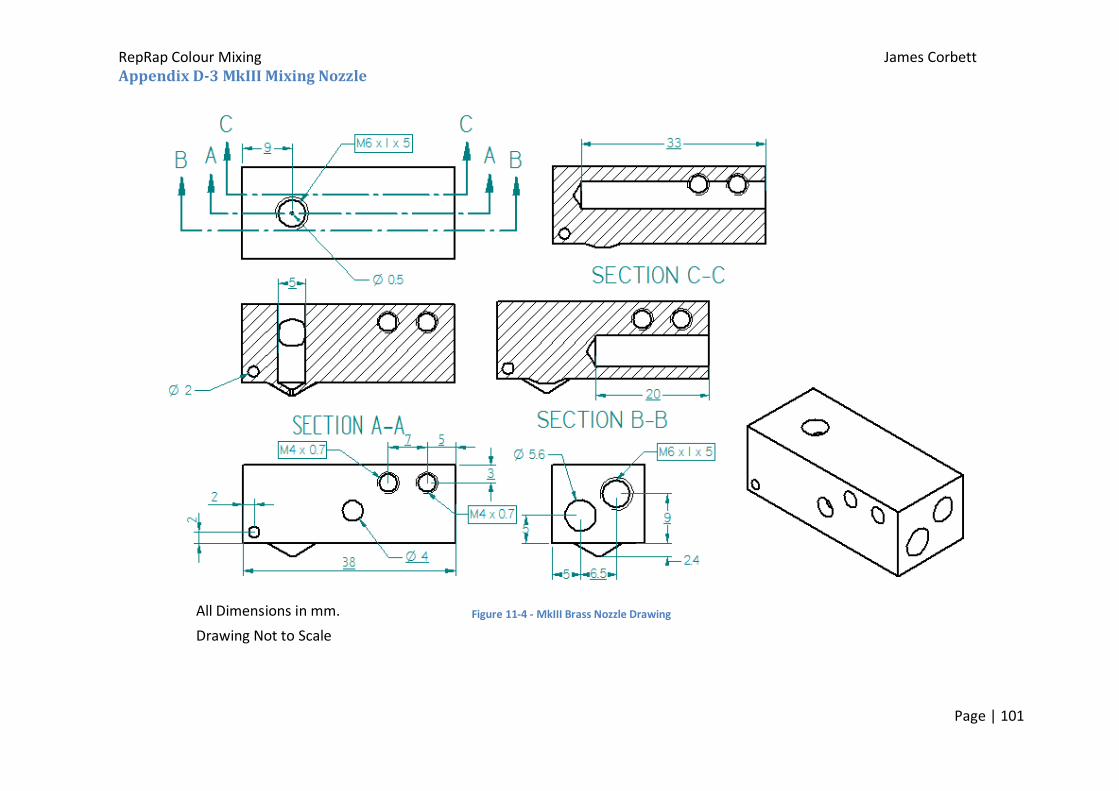
6.4.2. MkIII Nozzle Design
Introduction
Following the MkII nozzle results it was clear that a longer mixing length is needed to
start working towards homogeneous mixing and with this in mind the MkIII nozzle (figure 6-
15 and Appendix D-2) was designed with a horizontal mixing chamber with a length of 1 ¼”
and a vertical chamber the equivalent size to that within the MkII nozzle. This resulted in an
available mixing length of nearly 1 ½” in total. This longer mixing length will enable a coarser
RepRap Colour Mixing James Corbett
Page | 60
pitch thread to be used on the inserts which should result in lower extrusion forces
compared to the MkII design and screw thread inserts.
Figure 6-15 - MkIII nozzle with exploded parts, side view showing a long mixing insert (left) and end view showing the arrangement of the heater resistor and mixing insert (right)
Apparatus
1. Mixing Nozzle MkIII (Figure 6-15 & Appendix D-3) with heater resistor and 100k axial
thermistor in place.
2. 4mm OD (2mm ID) PTFE Tubes
3. Length of M6 threaded rod 12mm and locking nut.
4. Long Mixing Insert (overall length approx 1 ½”)
5. PEEK insulators (M6 internal thread)
6. M4 Grub Screw
Method
The MkIII nozzle was tested in an identical method to the MkII by first printing a control
print with just an empty mixing chamber, which as expected produced a print practically
identical to the previous prints figure 6-17. Following this, the brass inserts seen in figure 6-
16 were all tested with the nozzle held in a vice.
Mixing Chamber
Heater Resistor
Mixing Insert
Chamber Blank and PEEK Insulator
Axial Thermistor Hole
Heater Resistor Wiring Hole
Bowden Tube Threads
RepRap Colour Mixing James Corbett
Page | 61
-
Figure 6-16 – Brass Long Inserts, No.5 Single Reversal Insert Pitch-3.4mm Depth of Cut-1.5mm Tool-60° thread cutting tool (left), No.6 Multiple Reversal with a Pineapple (Left and Right Hand Thread cut together) Pitch-3.4mm Depth of Cut-1.5mm Tool-60° thread cutting tool at an angle of 20° to perpendicular (centre), No.7 Straight insert with multiple baffles and filed slots (right).
Results and Discussion
Manufacturing the inserts illustrated in figure 6-16 proved to be very difficult and a
cutting tool had to be ground to shape in order to achieve the coarse pitch of 3.4mm, the
problem encountered was due to the tool side relief angle (figure 6-18) was smaller than the
cutting angle on the material, this caused undue pressure on the material being cut causing
many failures during machining (figure 6-17).
Figure 6-17 - Two examples of the brass failing during thread cutting due to lack of relief angle on the tool.
RepRap Colour Mixing James Corbett
Page | 62
Figure 6-18 - Lathe Tooling Geometry [36]
All of the specialist custom threads for these inserts were cut by turning the lathe by
hand to reduce the forces on the piece, the relatively deep cuts mean the remaining
effective core is very small (approximately 2mm diameter) and any undue forces caused
failure of the piece. It was tried using aluminium instead of brass to fabricate the insert but
aluminium proved far too soft to cut deep threads on as the aluminium simply bent over the
tool.
No.5 insert was tested by hand first which immediately flagged up a problem with the
configuration of the design, having the mixing chamber to one side left the PTFE tubes on
the respecting side with very little retaining thread in the block and as soon as the pressure
was applied with the hand feeding this caused the PTFE tube to be forced out, rendering the
feed tubes holes on one side of the nozzle to be unusable. The feed tubes were blanked off
and experimentation was continued using the feed tubes on the opposite side which had
ample thread holding the tubes in place. The original hypothesis for using the layout of the
mixing chamber with the heater resistor on the same axis and staggered, as can be seen in
RepRap Colour Mixing James Corbett
Page | 63
the drawing (figure 6-19), was to reduce the thermal mass of the nozzle keeping the overall
depth of the nozzle to a minimum.
Figure 6-19 - MkIII nozzle drawing showing the internal arrangement
With both PTFE tubes mounted on the same side the testing using hand feeding was
continued with insert No. 5 (figure 6-20), the force required to drive the filament into the
nozzle was excessive and required the use of pliers to easily get the plastic flowing through
the nozzle tip. If too much force was applied to the filaments, by means of using pliers to
create much higher pressures, problems became apparent with the PTFE tubes as the
ballooning effect that was seen in early experiments became much more of a problem and
the tubes ruptured under these pressures (figure 6-21). It was apparent that the stepper
motors would be unable to create the pressure required to extrude the filament and when
this was tried the hobbed bolt simply stripped the plastic filament and failed to extrude
resulting in no print being produced.
From this No. 6 insert was made using the same cutting tool but at an angle to remove
more material creating a bigger cross section for the plastic to flow through thus reducing
the pressure required to feed the plastic through the nozzle. This was proved when hand
feeding which required significantly lower forces to drive the filament although still relatively
high compared to the MkII nozzle. The mixing performance of the nozzle was unchanged
RepRap Colour Mixing James Corbett
Page | 64
from before and still two distinct black and white streaks were produced in the extruded
plastic.
Figure 6-20 - MkIII Nozzle set up in a vice for manual testing.
Figure 6-21 - MkIV Nozzle with ruptured PTFE feed tube, Insert: close up picture of ballooning PTFE tube.
PTFE tube ruptured from
excessive pressure.
RepRap Colour Mixing James Corbett
Page | 65
When attempting to print the stepper motors struggled; drive of the filament was
intermittent and could not consistently drive the filament to produce a print, the
temperature was increased to 220°C to see if the reduced viscosity associated with the
increase in temperature aided the stepper motors but this created no noticeable difference.
Another attempt was made to print but at a much slower extrusion speed in the hope that
slower extrusion speed would allow time for the plastic to flow slower through the nozzle
but this caused no difference in the printing performance of the machine.
No. 7 insert concept was first thought up by Bowyer and was much simpler to
manufacture compared to previous designs of the screw thread concept, this new insert
consisted of a solid shaft with various baffles along the length with slots cut to allow the
plastic to flow to the next segment. With this insert in place hand testing proceeded and
resulted in much lower extrusion force compared to that of the previous inserts, although
the mixing quality was almost indifferent to that compared to the first print with no insert.
Conclusion
The MkIII nozzle was unsuccessful in attempting to cause a substantial amount of mixing,
it was unclear exactly how much was caused by inserts No. 6 & 7 due to the very high back
pressures meant that only very little amounts of plastic could be extruded there did appear
to be regions of grey in some of the extruded plastic but this was thought to be due to
thermal decomposition of the PLA as it only occurred when the nozzle was left at
temperature before attempting extrusion.
It was clear from early testing that the design of this nozzle was flawed as even if the
mixing inserts did work, the second filament would have been fed into the mixing chamber
¼” further down the mixing chamber than the first. This would result in subsequent
RepRap Colour Mixing James Corbett
Page | 66
filaments being fed into the chamber a ¼” further down, so if four filaments were intended
for use with this nozzle the final filament would have been almost feed into the very last
section of the mixing insert meaning that very little mixing could take place. Therefore it was
chosen to manufacture a larger design of nozzle where both filaments, or even up to four
filaments, could be fed into the very beginning of the mixing insert.
6.4.3. MkIV Nozzle Design
Introduction
The MkIV mixing nozzle was similar design to that of the MkIII except that the depth was
increased which enabled the heater resistor to be position perpendicular directly below the
mixing chamber which permitted the position of the mixing chamber central in the block,
giving equal thread depths for the PTFE feed tubes to achieve substantial purchase on the
nozzle. Consequently the thermal mass of the MkIV nozzle was substantially increased from
that of the MkIII, which in itself had a substantially long heat up time, this meant that the
nozzle would be benefitted with fibre glass insulation to minimise the heat loss due to
convection around the nozzle. In addition this nozzle was designed for the vertical mixing
chamber section to be expanded to M8 or M10 to enable the fitting of a gauze insert causing
finer mixing at a later stage.
With these modifications the nozzle would be tested as with previous designs and the
same inserts as with the MkIII nozzle to test whether mixing using these inserts is possible
when using their entire length. If mixing is achieved uniformly with these inserts then a new
filament drive system would have to be designed to create the forces required for extrusion.
RepRap Colour Mixing James Corbett
Page | 67
Apparatus
1. Mixing Nozzle MkIV (Figure 6-20 & Appendix D-4) with heater resistor and 100k axial
thermistor in place.
2. 4mm OD (2mm ID) PTFE Tubes
3. Length of M6 threaded rod 12mm and locking nut.
4. Long Mixing Inserts (overall length approx 1 ½”)
5. PEEK insulators (M6 internal thread)
6. Woven Fibreglass Thermal Insulation [37]
Method
The testing procedure was identical for the MkIV nozzle as with the MkIII nozzle except
for the nozzle was wrapped in PTFE insulating tape on all sides to reduce the heat loss from
the brass surface and the sides of the nozzle were wrapped once with woven fibreglass
insulation to further reduce heat loss. This was found to be necessary as the nozzle was
tested without insulation which proved the heater resistor could not dissipate enough heat
into the block to raise the temperature and maintain 200°C.
Figure 6-22 - MkIV Nozzle sketch showing the layout
Results and Discussion
It became apparent early on that the thermal mass of this nozzle caused excessively long
heat up times and took longer than the heated bed on a machine to warm up. Even with the
RepRap Colour Mixing James Corbett
Page | 68
thermal insulation the heater resistor was on permanently to maintain a temperature
between 195 – 200°C when not extruding, this would become problematic during printing as
the constant flow of plastic would take a certain amount of heat from the nozzle, which
would cause the temperature of the nozzle to drop to a less than optimum temperature.
All of the inserts from the MkIII nozzle were trialled with the MkIV nozzle and despite
both filaments being fed being forced down the entire length of the mixing inserts, the
mixing quality was still far from satisfactory and the two separate filaments formed a two
colour extruded plastic, which can be seen in figure 6-23.
Figure 6-23 - Manual Feed results for the MkIV nozzle, white and black are clearly unmixed.
Following this failure one final idea to use stainless steel gauze tightly coiled within the
mixing chamber was attempted which can be seen in figure 6-24. The theory behind the use
of gauze was that the amount of shear generated from passing through the small holes
would be much greater than that from the previously used threads, although the viscous
friction in theory should be increased due to the large surface area of contact between the
fluid and insert. The additional viscous friction was cancelled out by the very low velocity of
the fluid so this proved not to be a problem and the forces required to drive the filaments
RepRap Colour Mixing James Corbett
Page | 69
was much reduced from that required with the screw thread inserts which would be easily
Figure 6-25 - MkIV nozzle print with the stainless steel gauze inserts compared with the original print from the MkI nozzle (left) and the gauze insert from after the print (right)
The results from using the gauze were unchanged from the previous inserts which can be
seen in figure 6-25, two distinct colours can be seen in the print and from the removed
gauze after the print was finished it can be seen how each colour flowed down either side of
the gauze remaining completely separate from each other.
RepRap Colour Mixing James Corbett
Page | 70
Conclusion
It was clear from these results that there was little improvement in performance of the
nozzle from utilising the entire mixer insert length and that to achieve successful mixing
another approach should be taken.
6.4.4. Conclusions from Static Mixer Nozzle Development
Testing showed that using the concepts from plastic injection moulding, using static
mixer inserts, were flawed for this application into 3DP. None of the tested methods gave
results that were promising to reach homogeneous mixing, the length of mixer required to
achieve this is far greater than can be applied to the machine and the associated thermal
mass would be excessive, resulting in multiple heater resistors. The other associated
problems with a longer mixing nozzle are the pressures required to extrude the plastic
increase drastically far beyond that which can be produced by existing nozzle design, as well
as the PTFE tubing failing which would mean a direct extruder would have to be mounted on
the nozzle if the forces were to be achieved, even then the stepper motors would be likely to
stall.
From these trials the static mixer nozzle seemed impractical as non of the results were
remotely close to that desired, if there were better results then further development of
extruders and Bowden tubes may have been worthwhile to increase the feeding forces, but
the margins required were too great. Therefore it was decided to trial using an active mixing
system to generate the shear required for mixing the plastic within the nozzle, this would
solve any problems associated with high nozzle pressures as the shear energy would come
from an external source so the major components of the machine could remain.
RepRap Colour Mixing James Corbett
Page | 71
6.5. Active Mixer Nozzle Development
6.5.1. MkI Active Mixer Nozzle Design
Introduction
Active mixing creates many more problems and requires careful design, the main issue
surrounding this method would be sealing the mixing chamber to prevent leaks, this is
difficult due to the high operating temperature of the nozzle so the seal would have to be
able to withstand 200°C continuous use (as prints can take several hours to complete). One
advantage which could aid this sealing is the internal pressure within the nozzle is relatively
high so the design could incorporate this pressure to keep any seal on its seat. The most
obvious O-ring material to use was Silicone which is rated to operate at 200°C.
Initially a 12V geared down DC motor was selected to drive the mixer (as the RepRap
operates at 12V) so the torque available for a mixer was not immense so precautions should
be taken to reduce the drag from the mixer. The designs used for mixers were initially just be
a cylinder turning within a hole approximately 0.5mm diameter larger than the cylinder,
which would create plenty of mixing shear within the fluid, although this might cause to
much friction for the motor, or another option was to use a hexagonal bar within a hole
0.4mm diameter larger than that across the points of the bar, this would create higher shear
regions than the cylinder but less resistance to the motor. The direction of drive of the
mixing shaft was clockwise ensure the mixing camber sealing bolt could not be loosened by
friction on the shaft.
The design was based around the MkIV static mixing nozzle with a horizontal long mixing
chamber and a short vertical mixing chamber before the nozzle, the active mixer would be
located in the horizontal chamber and the vertical chamber was left in the design so that
RepRap Colour Mixing James Corbett
Page | 72
stainless steel gauze insert could be used if the final mix was not entirely homogeneous the
layout can is illustrated in figure 6-26.
-
Figure 6-26 - Cross Section View of Active Mixing Nozzle MkI
Figure 6-27 - Active Mixing Nozzle MkI in situ on the RepRap completing the first print
RepRap Colour Mixing James Corbett
Page | 73
Apparatus
1. Assembled Active Mixing Nozzle MkI (Figure 6-26/27 & Appendix D-5) with heater
From previous experiments it was clear that the pressure required to drive the filament
through this nozzle would be easily within the limits of the current extruder set-up, also the
12V motor was fixed to the X-carriage of the machine, so the nozzle was initially tested in
situ driven electronically to observe the results, first with the cylinder mixing insert then
repeat with the hex insert.
First the nozzle was heated up to 200°C before turning on the electric motor and then
the motors were told to extrude 25mm of filament at a time until the plastic was fed out of
the nozzle.
Following the initial trial, test prints can be carried out to see the dynamic performance
of the mixing nozzle. The nozzle must be preheated up to at least 185 degrees before the
mixing motor is turned on and the motor should be turned off when the nozzle is not in use
(i.e. not printing /extruding).
Results and Discussion
While using the cylindrical mixing insert the 12V DC motor stalled constantly and the
motor emerged to be underpowered to drive the mixing insert as the viscous friction of the
molten plastic appeared to be too much for the motor so the test was repeated with the hex
RepRap Colour Mixing James Corbett
Page | 74
mixing insert which gave promising results. Black and white filaments were fed
simultaneously and a consistent dark grey/black plastic was extruded from the nozzle, the
filament drive motors had no problem driving the filament and neither did the mixing motor,
which ran consistently whether or not filament was being driven. Following this result the
test print was carried out, which although was a poor quality print, showed very good mixing
qualities which appeared to the naked eye to be a homogeneous mix. The printer settings
were calibrated to produce a better quality print which can be seen compared to the first
print and the original control print from Bowyers mixer nozzle n figure 6-28. There was a
slight leaking issue from around the mixing shaft which accumulated to a single bead over a
15 minute print (figure 6-29) which will require a redesign of the O-ring arrangement with
the possible addition of a second O-ring.
Figure 6-28 - Comparison of Prints; (left) original print from the MkI Static Mixer Nozzle, (centre) First print from Active Nozzle MkI, (right) calibrated second print using the Active Mixing Nozzle
Figure 6-29 - First mixing print from the active nozzle
Single drop leaking from seal
RepRap Colour Mixing James Corbett
Page | 75
Figure 6-30 - Various colours mixes producing very identical quality prints with good mixing quality Appendix K
Conclusion
The active mixing nozzle performed well and produced well mixed prints as can be seen
from figure 6-30. It became apparent that the vertical part of the mixing chamber was
unnecessary as the quality of mixing was sufficient from the hex mixer, but there was a slight
leaking issue from the seal which should be addressed in the next design. This design was
primarily built to test the concept of using an active mixer and was less than ideal for
practical use, there were two main issues which were; the motor and mixer being mounted
horizontally meant that the X-travel of the machine was compromised and secondly the
motor and insulator shaft was very low relative to the nozzle tip which would foul on a print
with a large area.
RepRap Colour Mixing James Corbett
Page | 76
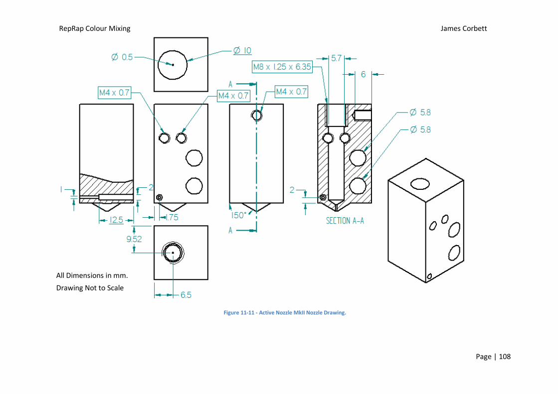
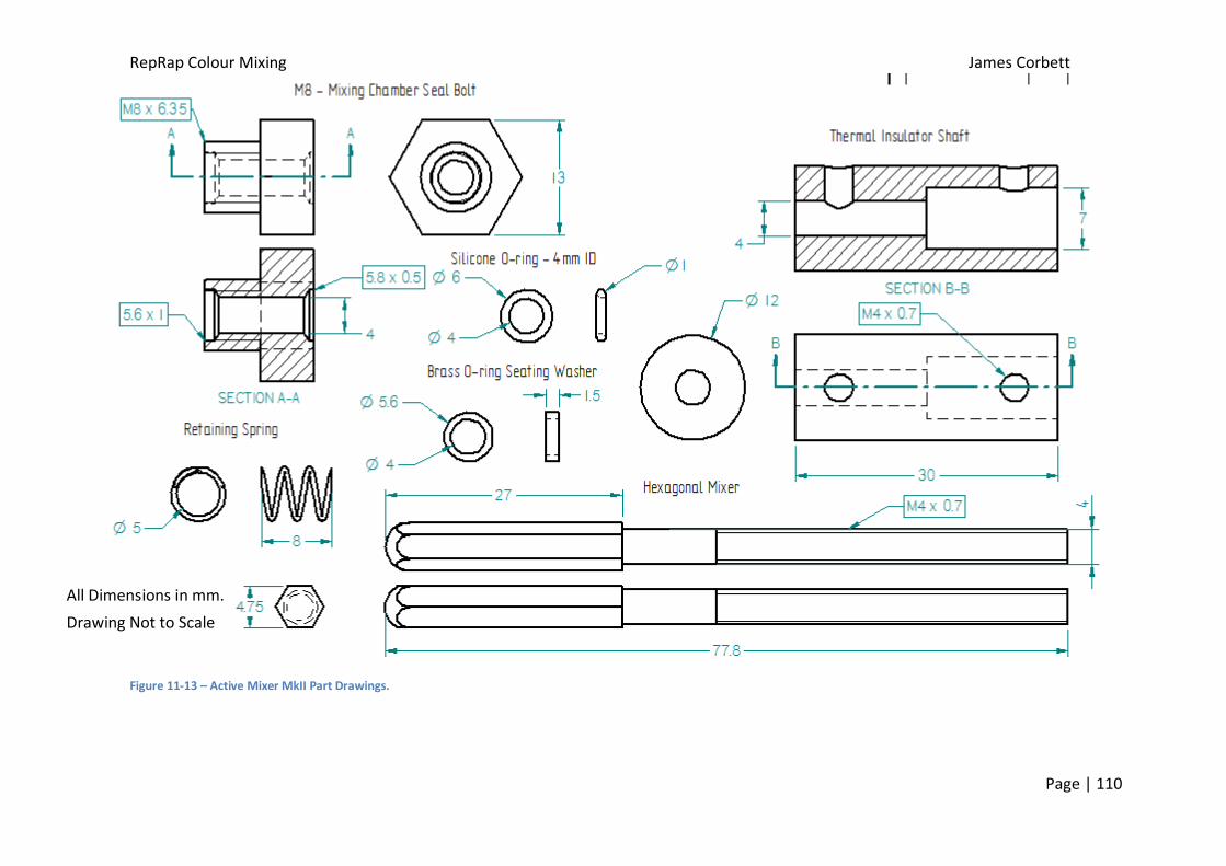
6.5.2. MkII Active Mixer Nozzle Design
Introduction
Following the results from the MkI Active Mixing Nozzle the design was reiterated with
various improvements; the extra section of mixing chamber was eliminated to reduce the
volume of plastic within the nozzle to minimise the plastic that has to be extruded to change
colour; the mixer was mounted vertically to restore the print area of the machine back to its
original size and reduce the chance of the motor and other parts fouling on the print due to
the limited clearance between the nozzle tip; the M8 mixing chamber seal bolt had an
improved seat for the O-ring to illuminate the leaking from the previous design. This design
incorporated two heater resistors to reduce the warm up time and enable higher
temperatures to be reached for printing. The MkII design can be seen in Appendix D-6 and
the set-up can be seen in figure 6-31, the second outer O-ring in this design was not
designed to act as a seal as the spring was very weak, this seal was put in place for the M4
washer to seat on and reduce wear, the spring was designed so that it could be removed and
the M4 nuts tightened on the outer O-ring to create a seal to stop any leaking if it becomes
an issue.
Figure 6-31 - MkII Active Nozzle Set-up
RepRap Colour Mixing James Corbett
Page | 77
Apparatus
1. Assembled Active Mixing Nozzle MkII (figure 6-31 & Appendix D-6) with heater
resistor x 2, 100k axial thermistor, Hex Mixer, Brass Washer, M4 Washer x 2, M4 Nut
x 2, Silicone O-ring x 2, PEEK Insulator, 12V DC geared motor and support all in place
as in figure 6-27.
2. 4mm OD (2mm ID) PTFE Tubes
3. Length of M6 threaded rod 12mm and locking nut.
4. PEEK insulator (M6 internal thread)
Method
This nozzle was tested using the same method as the MkI nozzle before testing
proceeded with printing performance testing (section 6.2.2)
Results and Discussion from Mixing Performance Testing
The mixing qualities of this nozzle were uncompromised from the previous design and
produced a practically identical print (figure 6-32). Following this result a larger print was
carried out (figure 6-33) to further test the performance of the nozzle, and the possible print
quality of the new design, which was unchanged from using a standard calibrated machine.
Figure 6-32 - MkI (left) and MkII (right) Active Nozzle prints with a 1:1 (black : white) ratio
RepRap Colour Mixing James Corbett
Page | 78
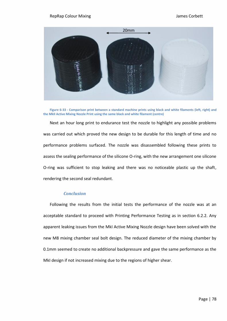
Figure 6-33 - Comparison print between a standard machine prints using black and white filaments (left, right) and the MkII Active Mixing Nozzle Print using the same black and white filament (centre)
Next an hour long print to endurance test the nozzle to highlight any possible problems
was carried out which proved the new design to be durable for this length of time and no
performance problems surfaced. The nozzle was disassembled following these prints to
assess the sealing performance of the silicone O-ring, with the new arrangement one silicone
O-ring was sufficient to stop leaking and there was no noticeable plastic up the shaft,
rendering the second seal redundant.
Conclusion
Following the results from the initial tests the performance of the nozzle was at an
acceptable standard to proceed with Printing Performance Testing as in section 6.2.2. Any
apparent leaking issues from the MkI Active Mixing Nozzle design have been solved with the
new M8 mixing chamber seal bolt design. The reduced diameter of the mixing chamber by
0.1mm seemed to create no additional backpressure and gave the same performance as the
MkI design if not increased mixing due to the regions of higher shear.
20mm
RepRap Colour Mixing James Corbett
Page | 79
7. Printing Performance Testing
Following the extruder development the printing performance of the nozzle needed to be
assessed more accurately to determine how the nozzle would perform under varying
printing conditions, mainly the altering the ratio of plastics fed into the nozzle.
7.1. Method of Testing
7.1.1. Single Colour Printing Method
With the printer set-up as before, disconnect one filament drive motor leaving
just one drive motor connected and change the extrusion multiplier in the Slic3r
settings to 1 from 0.5. White filament was left connected as small traces of black
would be easily visible.
Preheat the nozzle up to 200°C and extrude filament with the mixer motor
switched on until the single colour is cleanly extruded from the nozzle tip.
Upload a simple print into Pronterface (A cylinder diameter 20mm and height
15mm was used).
Send print and carefully monitor the machine to observe any problems that
emerge.
Analyse the print for defects/differences from a standard machine set up print.
Scan prints and analyse colours using Photoshop.
7.1.2. Mix Ratio Analysis Method
Firmware Alteration
For this method both filament drive motors should be connected but to different motor
outputs on the electronics board, one to E (extruder) and the other to Z (Y-axis). The
RepRap Colour Mixing James Corbett
Page | 80
firmware should be altered to accommodate this output to drive the extruder, changes
required for the Sprinter Firmware under the configuration tab are as follows (alterations
required will depend on the firmware used);
Change steps per mm of the Z-axis to equal the steps per mm of the E drive, in
this case 1050.
Invert Z-direction to false (will depend on the orientation of the motors and
wiring)
Increase Z max length to a large number such as 5000.
Testing Method
Pre-heat the nozzle up to 200°C and turn the mixing motor on.
By moving the Z-axis by hand, adjust the nozzle height to a couple of mm.
By typing a single line of G-code into Pronterface set the positioning system to
relative (G92 command).
Purge the nozzle with a filament ratio using the same method (e.g. for a ratio of
1:1 send G1 Z50 E50).
Clean the glass print surface, and then perform the same extrusion ratio onto the
glass plate.
Allow sample to cool and remove from print surface.
Repeat the purge with a different filament ratio, followed by an extrusion onto
the glass plate.
Repeat with as many ratios of filament as required.
Scan samples and analyse colour using Photoshop.
RepRap Colour Mixing James Corbett
Page | 81
7.2. Results and Discussion
7.2.1. Single Colour Prints
Initially the printing with one colour proved to be of good quality and showed minimal
problems, figure 7-1 shows the resulting prints with white and black being driven
independently for either print, these prints are compared to the quality from a standard set
up RepRap. The apparent poor quality finish of the prints from the mixer nozzle is due to
federate settings and can be solved by further calibration. This type of printing was enabled
by the PLA filament in the non-driven tube melting to a certain extent and effectively
blocking the tube opposing the internal pressure of the nozzle.
Figure 7-1 - Black only print with mixer nozzle (far left), black print from standard machine (left), white only print from mixer nozzle (right), white print from standard machine (far left)
Towards the end of the prints a problem arose with the PTFE feed tubes in the nearest
5mm to the hot end, with the prolonged heat and pressure from the mixing chamber the
feed tube ballooned as the PTFE at 200°C even though it does not melt, the strength is
greatly reduced allowing this stretching (figure7-2). This effect can be solved with further
development and insulation of the PTFE tube. A quick solution used for further experiments
was to use a PEEK sleeve approximately 10mm long with an internal diameter of 4mm which
provided extra hoop strength of the tube and stopped any rupturing of the PTFE tube. A
more permanent solution would be to incorporate the design used on the RepRapPro Huxley
RepRap Colour Mixing James Corbett
Page | 82
hot end [35] on which a stainless steel sleeve with a large heat sink and cooling fan are used,
this has the effect of minimising the transition region of the temperature.
Figure 7-2- 'Inflated' PTFE feed tube (left) which was shortly followed by the rupture (right)
The difference of 3% could easily be down to measurement variation from the scanning
or within the software, another cause of this error could be due to scanned surface not
being perfectly flat, and this can be most clearly seen on the mixer nozzle black print which
has light areas where the plastic was not in contact with the scanning glass. These regions
are quite small so the effect on the average colour measurement should not be affected
greatly.
7.2.2. Varying Mix Ratios of Filament
11 samples (figure7-5) were produced varying from 100% white to 100% black, the
samples were analysed and the results are plotted below (table 2). The graph shows how
much stronger the black pigment is compared to the white as the colour composition of the
samples is within 10% from pure black up to a ratio of 50% and it’s not until above 70%
where the difference is clearly noticeable in the colour of the samples.
The largest change in colour was at a ratio with more than 90% white, this would make
accurately predicting a colour composition of extruded plastic very difficult to calibrate as
the black filament needs to be very finely controlled and able to be driven at very slow rates.
The accurate driving of the filament is made harder by the Bowden tube as the hysteresis in
RepRap Colour Mixing James Corbett
Page | 84
the tube can build up and release causing fluctuations in the drive of the filament, due to the
sensitivity of the resulting colour being dependant on black these small fluctuations could
cause difficultly achieving a uniform colour. This could possibly be improved by mounting the
black filament drive on the X-carriage which would eliminate the hysteresis and give more
accurate control, the other filament drives could remain using Bowden tubes as their control
doesn’t have as much as effect as the black. Another solution to give the user more control
over the colour would be to use a black filament with a weaker/less pigment which would
mean each colour (black and white) would have a similar effect on the final colour.
Table 2 - Colour Composition of different proportions of black and white filament
Figure 7-5- Varying Colour Ratios samples, the slight light patches were due to thin parts of the sample or the sample not being in full contact with the scanning surface which had negligible effect on the average colour reading of the sample
0
10
20
30
40
50
60
70
80
90
100
0% 20% 40% 60% 80% 100%
Co
lou
r C
om
po
siti
on
(%)
Ratio of White Filament (%)
Cyan
Magenta
Yellow
Key
RepRap Colour Mixing James Corbett
Page | 85
8. Project Conclusions
Initial trials showed that the PLA plastic would mix to produce the expected colours
(similar to paints) and the relative strengths of the pigments in each filament were
approximately determined to be in the following order (strongest first); black, red, electric
blue, yellow then white. These colours were selected as they are the closest representation
to CMYK widely available.
This project showed that the use of a static mixing nozzle was impractical for this home
3D printer application due to the very high pressures required to drive the filament which
led to the drive mechanism stalling and slipping on the filament. Also the tests ran showed
no promising mixing results that deemed this method of inducing mixing impracticable to
pursue with development.
This led to the design of an active mixing system which consisted of a hexagonal bar
rotating within a cylinder 0.3mm larger diameter than that across the points on the bar, this
was driven by a 12V DC motor at a gear ratio of 200:1 and a turning speed of approximately
80rpm (max.). The results appeared to be homogeneously mixed with no visible streaks in
any of the prints produced, the nozzle was tested briefly with various combinations of two
filaments to produce a wider variety of colours.
Following these results a more practical configuration of the nozzle was fabricated to
simplify the design and eliminate initial minimal leaking problems, the new nozzle performed
faultlessly even over a longer print until the driven speed of the filaments were altered to
give different feed ratios. The slowing of one filament led to a build up of heat and pressure
in the end of the Bowden tubes which led to rupturing, this was temporarily solved using a
PEEK sleeve but will require further development to resolve the issue.
RepRap Colour Mixing James Corbett
Page | 86
While investigating the effect of varying the ratio of filament inputs it was made clear
how much stronger the black filament than white, the ratio of white to black had to be
30/40% before any noticeable difference in the colour can be seen to the eye and to make a
significant lightening to the black at least 80% white needs to be used. This would make
calibration very difficult as the colour printed is very dependent on the black filament and
any varying in the drive could cause large fluctuations in the colour printed, therefore the
black filament driver could be mounted closer (on the X-carriage) to increase the control of
the filament, or a weaker black filament could be developed which would give more control
of the colour as a greater change of ratio would be required to alter the colour.
Unfortunately time did not allow for detailed testing of colour proportion mixing and
alternating filament feeds to determine the purge volume of the nozzle and printability
which would lead into the investigation of the possibility of printing colour gradients. The
next stages of the development are outlined in the following section.
9. Further Work
The design of the nozzle leaves much to be desired with further development, firstly the
length of the mixer should be shortened in steps and subsequently tested at each length,
this will help determine the minimum length of mixing insert that can be used to produce
satisfactory mixing results. Following the optimisation of the length of the insert the original
nozzle can be shortened to the equivalent length of the insert, with the internal design of
the nozzle modified any excess material of the nozzle can be milled off. This modification will
reduce the thermal mass and the volume of plastic of the nozzle to a minimum which will
increase the thermal control and printability of the nozzle.
RepRap Colour Mixing James Corbett
Page | 87
As mentioned before the ballooning effect of the PTFE feed tubes needs to be addressed
possibly by using a stainless steel barrel connected to a heat sink being actively cooled by a
fan. This will require some careful design and manufacture to incorporate all the feed tubes
into one heat sink to result in the need for just a single fan, also the flow of air around the
nozzle will require special consideration to minimise the cooling of the nozzle which already
has compromised heating performance due to the large thermal mass.
With the previous modification in place the printability of the nozzle can be tested,
meaning the transition volume of plastic required to be extruded to alter between two mix
ratios. This can be tested by printing the Colour Transition Ladder G-code and using the
method found in Appendix J. The nozzle should be initially purged with black then the print
should be started and only white filament being driven. The colour of the extruded filament
should then be analysed to test at what stage of the print the colour has reached a
consistent composition. This will enable the determination of how much plastic needs to be
purged during a print to create a sharp colour transition.
Firmware and electrical modifications require the most development to accommodate
the new nozzle as they both need to incorporate the ability to independently control a
minimum of 5 separate filament drives (Black, White, Cyan, Magenta and Yellow) this may
be increased to also utilise colourless, water soluble or soft composition plastics. The
electronics and software development were far beyond the scope of this project but once
these modifications are in place it will enable the more comprehensive testing and
calibration of the nozzle drives. The control of the ratios of the filament drives would be
controlled using a widespread map across the full available colour space that could be
produced by the printer, this map would relate to CMYK percentage values as normal ink
printing does.
RepRap Colour Mixing James Corbett
Page | 88
Another feature that will be required of the firmware, will be a method to purge the
nozzle with the correct printing colour before applying the colour to the print, there are a
couple of theories to achieve this; the first is to print a block in tandem with the print which
will be used to purge material on, this method will be somewhat wasteful with having to
print this block for every print, also the size of this block will have to be increased for
multiple colour changes on the same layer. Another more economical solution would be to
use the infill of a part to purge the plastic to the correct colour, and possible the inner
boundary as the outer boundary will define the appearance of the object. This method will
create much less waste although will not be as practical if parts of an object are desired to
be clear as the infill will appear messy in terms of colour. Nor will this method be practical
when determining the hardness of an object by using hard and soft plastics or by printing
support material using water soluble material so a ‘purge print’ will have to be done
alongside prints with these features.
RepRap Colour Mixing James Corbett
Page | 89
10. References
1. The RepRap Kit Store Website. Products, The RepRapKitStore. [Online] [Cited : 27th
November 2011] http://www.thereprapkitstore.co.uk/products-2/