j ourna l ho me page: www.elsev ier .com/ locate /enbui ld
inancial analysis of the implementation of a Drain Water Heatecovery unit in residential housing
aniel Słys ∗, Sabina Kordanaepartment of Infrastructure and Sustainable Development, Rzeszów University of Technology, al. Powstanców Warszawy 12, 35-959 Rzeszów, Poland
r t i c l e i n f o
rticle history:eceived 24 May 2013eceived in revised form7 September 2013ccepted 23 November 2013
eywords:
a b s t r a c t
One of the ways of diminishing energy consumption for hot water heating is the use of Drain Water HeatRecovery (DWHR) units. The aim of the use of these devices is thermal energy recovery from warm drainwater and transferring it to incoming cold water. This paper presents the calculation model that allowsthe estimation of the financial efficiency of the project involving the construction of a shower DrainWater Heat Recovery system in a single-family dwelling house. The presented method of investmentrisk assessment can be used for decision making by individual users, designers and others. The study ofthe financial performance was carried out for the various parameters of the installation and the different
aste heat recoveryrain Water Heat RecoveryWHR unitinancial performancehower
heat recovery system configurations. From investors point of view the most beneficial option of heatrecovery system installation is the system in which preheated water is fed to both the hot water heaterand shower mixing valve. Additionally, it was proved that obtained financial results are affected byshowering time and water consumption. DWHR units will be therefore particularly beneficial to apply
ls, spo
ot water heaternergy conservation
in case of swimming poo
. Introduction
Energy efficiency has now become one of the indicators of eco-omic development, and the rationalization of its use is the subjectf numerous scientific studies [1–5]. Around the world, the aim is toinimize the negative impact of energy on the environment, espe-
ially in those industries that contribute most to its degradation.ata from the International Energy Agency [6] show that in 2010arbon dioxide emissions from the combustion of fuels in the worldmounted to 30,326 Mt. It was an increase of almost 94% in com-arison to 37 years earlier, that is to 1973, when the emissions werequal to 15,637 Mt. The increase in the amount of greenhouse gasesntering the atmosphere is a consequence of the increased energyemand resulting from population growth in the world, as well ashe ongoing development of civilization. Environmental pollutionaused by excessive CO2 emissions resulting from the combustionf fossil fuels, raises the need to seek solutions that will contributeo energy saving, and thereby also protect the atmosphere.
According to the Central Statistical Office of Poland [7], house-olds are responsible for about 32% of final energy consumption
n Poland. The result is that the interest in using unconventional
ethods of saving energy is becoming more evident also in the con-
truction sector. The most frequently considered methods are thosehat allow the reduction of energy consumption for space heating
[8–10], but it is also worth considering using methods whose usecontributes to reducing the energy demand for hot water which, asMeggers and Leibundgut suggest [11], may in some cases constituteup to 50% of the total demand.
The problem of saving the energy used to heat water for domes-tic usage has been observed in some countries such as the UnitedKingdom [12], Ireland [13], Algeria [14], Netherlands [15], Canada[16–18], Australia [19] and Brazil [20], where the effectiveness ofthe use of different technologies for saving energy used for heatingwater was analyzed.
Technologies used in order to reduce energy consumption forhot water heating include among others heat recovery from waste-water. Current development of technology makes it possible torecover heat from wastewater on every stage of its formation,transport and utilization. For instance, in works [21,22] installa-tions were described, in which wastewater flowing in collectors isthe lower energy source for heat pumps, whereas in publications[23–27] the systems were characterized, in which heat pumps areused in internal building installations. The above examples showthat with the use of heat pumps wastewater from various sani-tary facilities can be the only source of heat for hot water in theinstallation as well as used together with renewable sources such assolar energy or outside air. Additionally, the energy recovered fromwastewater may be also used for different purposes, for instance
for air conditioning or space heating.
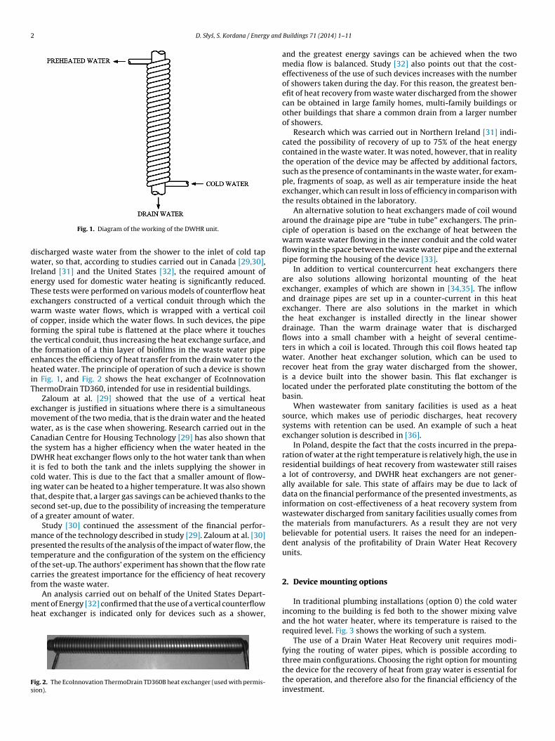
Another solution involves the installation of a Drain WaterHeat Recovery (DWHR) unit on the shower drain [16,17,28]. Withthis device there is a transfer of thermal energy contained in the
ischarged waste water from the shower to the inlet of cold tapater, so that, according to studies carried out in Canada [29,30],
reland [31] and the United States [32], the required amount ofnergy used for domestic water heating is significantly reduced.hese tests were performed on various models of counterflow heatxchangers constructed of a vertical conduit through which thearm waste water flows, which is wrapped with a vertical coil
f copper, inside which the water flows. In such devices, the pipeorming the spiral tube is flattened at the place where it toucheshe vertical conduit, thus increasing the heat exchange surface, andhe formation of a thin layer of biofilms in the waste water pipenhances the efficiency of heat transfer from the drain water to theeated water. The principle of operation of such a device is shown
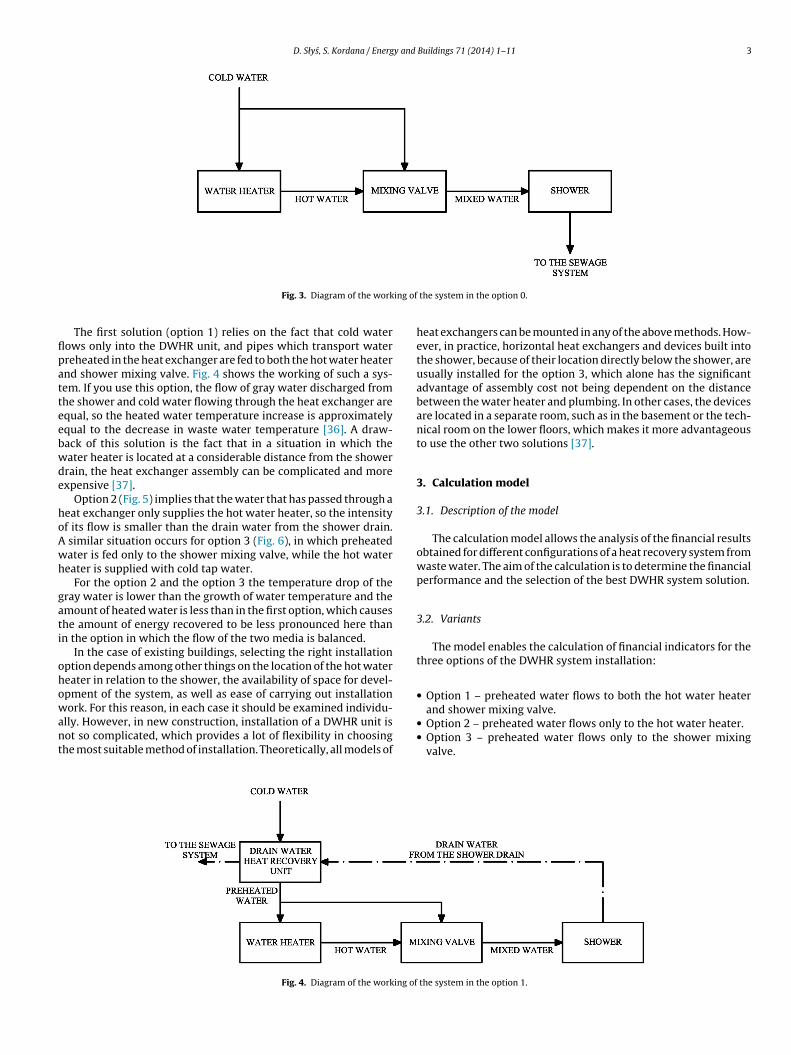
n Fig. 1, and Fig. 2 shows the heat exchanger of EcoInnovationhermoDrain TD360, intended for use in residential buildings.
Zaloum at al. [29] showed that the use of a vertical heatxchanger is justified in situations where there is a simultaneousovement of the two media, that is the drain water and the heatedater, as is the case when showering. Research carried out in theanadian Centre for Housing Technology [29] has also shown thathe system has a higher efficiency when the water heated in theWHR heat exchanger flows only to the hot water tank than when
t is fed to both the tank and the inlets supplying the shower inold water. This is due to the fact that a smaller amount of flow-ng water can be heated to a higher temperature. It was also shownhat, despite that, a larger gas savings can be achieved thanks to theecond set-up, due to the possibility of increasing the temperaturef a greater amount of water.
Study [30] continued the assessment of the financial perfor-ance of the technology described in study [29]. Zaloum at al. [30]
resented the results of the analysis of the impact of water flow, theemperature and the configuration of the system on the efficiencyf the set-up. The authors’ experiment has shown that the flow ratearries the greatest importance for the efficiency of heat recoveryrom the waste water.
An analysis carried out on behalf of the United States Depart-ent of Energy [32] confirmed that the use of a vertical counterflow
eat exchanger is indicated only for devices such as a shower,
ig. 2. The EcoInnovation ThermoDrain TD360B heat exchanger (used with permis-ion).
Buildings 71 (2014) 1–11
and the greatest energy savings can be achieved when the twomedia flow is balanced. Study [32] also points out that the cost-effectiveness of the use of such devices increases with the numberof showers taken during the day. For this reason, the greatest ben-efit of heat recovery from waste water discharged from the showercan be obtained in large family homes, multi-family buildings orother buildings that share a common drain from a larger numberof showers.
Research which was carried out in Northern Ireland [31] indi-cated the possibility of recovery of up to 75% of the heat energycontained in the waste water. It was noted, however, that in realitythe operation of the device may be affected by additional factors,such as the presence of contaminants in the waste water, for exam-ple, fragments of soap, as well as air temperature inside the heatexchanger, which can result in loss of efficiency in comparison withthe results obtained in the laboratory.
An alternative solution to heat exchangers made of coil woundaround the drainage pipe are “tube in tube” exchangers. The prin-ciple of operation is based on the exchange of heat between thewarm waste water flowing in the inner conduit and the cold waterflowing in the space between the waste water pipe and the externalpipe forming the housing of the device [33].
In addition to vertical countercurrent heat exchangers thereare also solutions allowing horizontal mounting of the heatexchanger, examples of which are shown in [34,35]. The inflowand drainage pipes are set up in a counter-current in this heatexchanger. There are also solutions in the market in whichthe heat exchanger is installed directly in the linear showerdrainage. Than the warm drainage water that is dischargedflows into a small chamber with a height of several centime-ters in which a coil is located. Through this coil flows heated tapwater. Another heat exchanger solution, which can be used torecover heat from the gray water discharged from the shower,is a device built into the shower basin. This flat exchanger islocated under the perforated plate constituting the bottom of thebasin.
When wastewater from sanitary facilities is used as a heatsource, which makes use of periodic discharges, heat recoverysystems with retention can be used. An example of such a heatexchanger solution is described in [36].
In Poland, despite the fact that the costs incurred in the prepa-ration of water at the right temperature is relatively high, the use inresidential buildings of heat recovery from wastewater still raisesa lot of controversy, and DWHR heat exchangers are not gener-ally available for sale. This state of affairs may be due to lack ofdata on the financial performance of the presented investments, asinformation on cost-effectiveness of a heat recovery system fromwastewater discharged from sanitary facilities usually comes fromthe materials from manufacturers. As a result they are not verybelievable for potential users. It raises the need for an indepen-dent analysis of the profitability of Drain Water Heat Recoveryunits.
2. Device mounting options
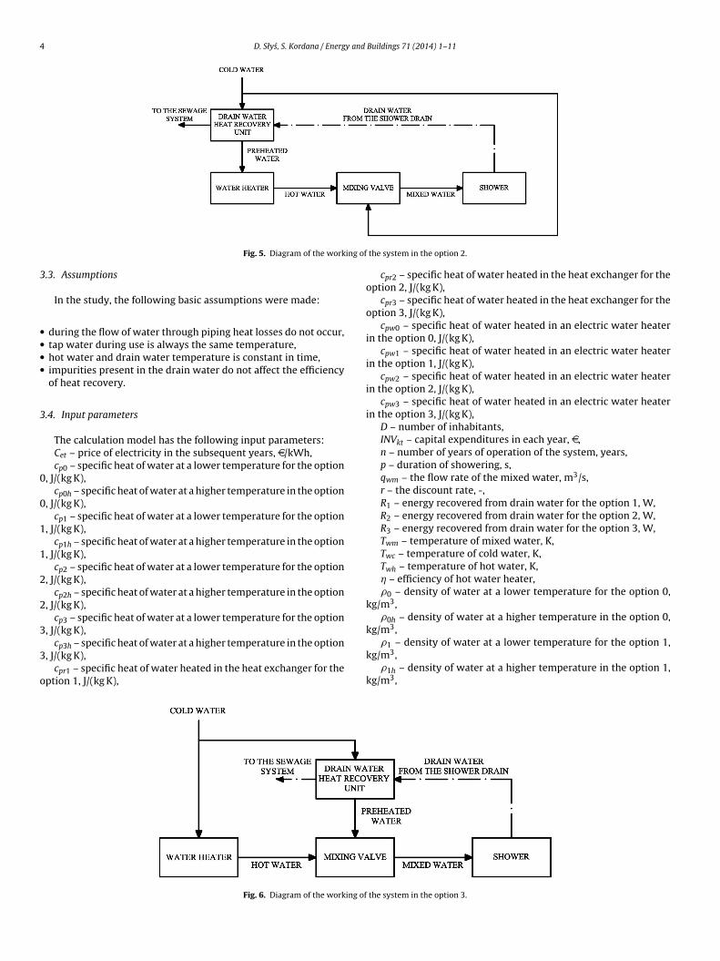
In traditional plumbing installations (option 0) the cold waterincoming to the building is fed both to the shower mixing valveand the hot water heater, where its temperature is raised to therequired level. Fig. 3 shows the working of such a system.
The use of a Drain Water Heat Recovery unit requires modi-fying the routing of water pipes, which is possible according to
three main configurations. Choosing the right option for mountingthe device for the recovery of heat from gray water is essential forthe operation, and therefore also for the financial efficiency of theinvestment.
D. Słys, S. Kordana / Energy and Buildings 71 (2014) 1–11 3
ing of
flpatteebwde
hoAwh
gati
ohowant
Fig. 3. Diagram of the work
The first solution (option 1) relies on the fact that cold waterows only into the DWHR unit, and pipes which transport waterreheated in the heat exchanger are fed to both the hot water heaternd shower mixing valve. Fig. 4 shows the working of such a sys-em. If you use this option, the flow of gray water discharged fromhe shower and cold water flowing through the heat exchanger arequal, so the heated water temperature increase is approximatelyqual to the decrease in waste water temperature [36]. A draw-ack of this solution is the fact that in a situation in which theater heater is located at a considerable distance from the showerrain, the heat exchanger assembly can be complicated and morexpensive [37].
Option 2 (Fig. 5) implies that the water that has passed through aeat exchanger only supplies the hot water heater, so the intensityf its flow is smaller than the drain water from the shower drain.
similar situation occurs for option 3 (Fig. 6), in which preheatedater is fed only to the shower mixing valve, while the hot watereater is supplied with cold tap water.
For the option 2 and the option 3 the temperature drop of theray water is lower than the growth of water temperature and themount of heated water is less than in the first option, which causeshe amount of energy recovered to be less pronounced here thann the option in which the flow of the two media is balanced.
In the case of existing buildings, selecting the right installationption depends among other things on the location of the hot watereater in relation to the shower, the availability of space for devel-pment of the system, as well as ease of carrying out installation
ork. For this reason, in each case it should be examined individu-
lly. However, in new construction, installation of a DWHR unit isot so complicated, which provides a lot of flexibility in choosinghe most suitable method of installation. Theoretically, all models of
Fig. 4. Diagram of the working of
the system in the option 0.
heat exchangers can be mounted in any of the above methods. How-ever, in practice, horizontal heat exchangers and devices built intothe shower, because of their location directly below the shower, areusually installed for the option 3, which alone has the significantadvantage of assembly cost not being dependent on the distancebetween the water heater and plumbing. In other cases, the devicesare located in a separate room, such as in the basement or the tech-nical room on the lower floors, which makes it more advantageousto use the other two solutions [37].
3. Calculation model
3.1. Description of the model
The calculation model allows the analysis of the financial resultsobtained for different configurations of a heat recovery system fromwaste water. The aim of the calculation is to determine the financialperformance and the selection of the best DWHR system solution.
3.2. Variants
The model enables the calculation of financial indicators for thethree options of the DWHR system installation:
• Option 1 – preheated water flows to both the hot water heater
and shower mixing valve.
• Option 2 – preheated water flows only to the hot water heater.• Option 3 – preheated water flows only to the shower mixing
valve.
the system in the option 1.
4 D. Słys, S. Kordana / Energy and Buildings 71 (2014) 1–11
ing of
3
••••
3
0
0
1
1
2
2
3
3
o
Fig. 5. Diagram of the work
.3. Assumptions
In the study, the following basic assumptions were made:
during the flow of water through piping heat losses do not occur,tap water during use is always the same temperature,hot water and drain water temperature is constant in time,impurities present in the drain water do not affect the efficiencyof heat recovery.
.4. Input parameters
The calculation model has the following input parameters:Cet – price of electricity in the subsequent years, D/kWh,cp0 – specific heat of water at a lower temperature for the option
, J/(kg K),cp0h – specific heat of water at a higher temperature in the option
, J/(kg K),cp1 – specific heat of water at a lower temperature for the option
, J/(kg K),cp1h – specific heat of water at a higher temperature in the option
, J/(kg K),cp2 – specific heat of water at a lower temperature for the option
, J/(kg K),cp2h – specific heat of water at a higher temperature in the option
, J/(kg K),cp3 – specific heat of water at a lower temperature for the option
, J/(kg K),
cp3h – specific heat of water at a higher temperature in the option
, J/(kg K),cpr1 – specific heat of water heated in the heat exchanger for the
ption 1, J/(kg K),
Fig. 6. Diagram of the working of
the system in the option 2.
cpr2 – specific heat of water heated in the heat exchanger for theoption 2, J/(kg K),
cpr3 – specific heat of water heated in the heat exchanger for theoption 3, J/(kg K),
cpw0 – specific heat of water heated in an electric water heaterin the option 0, J/(kg K),
cpw1 – specific heat of water heated in an electric water heaterin the option 1, J/(kg K),
cpw2 – specific heat of water heated in an electric water heaterin the option 2, J/(kg K),
cpw3 – specific heat of water heated in an electric water heaterin the option 3, J/(kg K),
D – number of inhabitants,INVkt – capital expenditures in each year, D,n – number of years of operation of the system, years,p – duration of showering, s,qwm – the flow rate of the mixed water, m3/s,r – the discount rate, -,R1 – energy recovered from drain water for the option 1, W,R2 – energy recovered from drain water for the option 2, W,R3 – energy recovered from drain water for the option 3, W,Twm – temperature of mixed water, K,Twc – temperature of cold water, K,Twh – temperature of hot water, K,� – efficiency of hot water heater,�0 – density of water at a lower temperature for the option 0,
kg/m3,�0h – density of water at a higher temperature in the option 0,
kg/m3,
�1 – density of water at a lower temperature for the option 1,
kg/m3,�1h – density of water at a higher temperature in the option 1,
kg/m3,
the system in the option 3.
y and
k
k
k
k
1
2
3
o
o
o
o
3
•••
cwtaa
N
wdd
d
•
••
C
wi
d
S
D. Słys, S. Kordana / Energ
�2 – density of water at a lower temperature for the option 2,g/m3,
�2h – density of water at a higher temperature in the option 2,g/m3,
�3 – density of water at a lower temperature for the option 3,g/m3,
�3h – density of water at a higher temperature in the option 3,g/m3,
�r1 – density of water heated in the heat exchanger for the option, kg/m3,
�r2 – density of water heated in the heat exchanger for the option, kg/m3,
�r3 – density of water heated in the heat exchanger for the option, kg/m3,
�w0 – density of water heated in an electric water heater in theption 0, kg/m3,
�w1 – density of water heated in an electric water heater in theption 1, kg/m3,
�w2 – density of water heated in an electric water heater in theption 2, kg/m3,
�w3 – density of water heated in an electric water heater in theption 3, kg/m3.
.5. Output and auxiliary variables
Numerical model output variables are financial indicators:
NPV – Net Present Value, DIRR – Internal Rate of Return, %DPP – Discounted Payback Period, years.
The Net Present Value (NPV) is the difference between dis-ounted revenues and expenses incurred for the undertakingithin an adopted time-scale. Cash flows are discounted as on
he investment starting moment [38,39]. The NPVk value, underssumption of the discount rate being fixed throughout the wholenalyzed period, is determined by formula (1).
here, NPVk – Net Present Value of the project option k, D, CFkt –esignated cash flow for the year t and the investment option k, D,t – the discount factor set for the year t,
t = 1
(1 + r)t(2)
NPV variable can have the following values:
NPV > 0 – discounted income from the project exceeds the valueof its capital expenditures and the project is cost-effectiveNPV = 0 – incomes equal capital expendituresNPV < 0 – capital expenditures are higher than the income fromthe investment and the project should be rejected because it isunprofitable.
CFkt cash flows for each year can be calculated from Eq. (3).
Fkt = −INVkt + Skt (3)
here, Skt – savings resulting from the use of a heat recovery systemn the coming years, D.
Savings in subsequent years of the system’s working can beetermined from the formula (4).
kt = (Cr0t − Crkt) · Cet (4)
Buildings 71 (2014) 1–11 5
where, Cr0t – electricity consumption for the option 0 without usingthe Drain Water Heat Recovery unit in year t, kWh, Crkt – electricityconsumption in the option k using the Drain Water Heat Recoveryunit in year t, kWh.
Amount of electricity consumed in a year by a water heater notinteracting with a Drain Water Heat Recovery unit can be deter-mined according to (5).
Cr0t = 365 · D · q0h · p · �w0 · cpw0 · (Twh − Twc)
� · 3.6 × 10⁶(5)
where, q0h – flow of water heated in an electric water heater for theoption 0, m3/s.
The annual demand for electricity consumed by an electric waterheater interacting with a DWHR unit installed in accordance withthe option 1, can be expressed by formula (6).
Cr1t = 365 · D · q1h · p · �w1 · cpw1 · (Twh − Twp1)
� · 3.6 × 10⁶(6)
where, q1h – flow of water heated in an electric water heater forthe option 1, m3/s, Twp1 – temperature of pre-heated water for theoption 1, K.
The annual demand for electricity consumed by an electricheater interacting with a DWHR unit, which is configured for theoption 2, can be expressed by formula (7).
Cr2t = 365 · D · q2h · p · �w2 · cpw2 · (Twh − Twp2)
� · 3.6 × 10⁶(7)
where, q2h – flow of water heated in an electric water heater forthe option 2, m3/s, Twp2 – temperature of pre-heated water for theoption 2, K.
The annual demand for electricity consumed by an electric waterheater interacting with a DWHR unit mounted under the option 3is described by formula (8).
Cr3t = 365 · D · q3h · p · �w3 · cpw3 · (Twh − Twc)
� · 3.6 × 10⁶(8)
where, q3h – flow of water heated in an electric water heater for theoption 3, m3/s.
The flow rate of hot water and cold water, which should be takento a shower in order to obtain a defined temperature of the mixedwater is calculated based on a heat balance equation, according towhich the amount of heat given out by the hot water is equal to theamount of heat taken by the cold water. If the hot water heater doesnot work with a DWHR unit, these relationships can be describedby the following system of equations (9).{
here, q3 – flow of pre-heated water for the option 3, m3/s, Twp3 –emperature of pre-heated water for the option 3, ◦C.
The amount of water that must be heated to a temperature of0 ◦C, and the temperature difference between the hot water andhe water supplied to the water heater and shower taps can beeduced by installing a DWHR unit on the outflow of the drain waterrom the sanitary facility. The temperature which the tap waterill be pre-heated to is determined by the efficiency of the heat
xchanger (Fig. 7) or the amount of energy recovered (Fig. 8), whichepends on the flow rate of water from the shower and durationf showering. In the latter case, the heated water temperature Twpk
ig. 8. Recovered energy as function of cold inlet and drain flow for model ECO-GFX340-A by EcoInnovation Technologies Inc. (used with permission).
Buildings 71 (2014) 1–11
is determined using the formula (14), (15) or (16) depending onassembly option k being used.
Twp1 = R1
�r1 · cpr1 · qhe1+ Twc (14)
Twp2 = R2
�r2 · cpr2 · qhe2+ Twc (15)
Twp3 = R3
�r3 · cpr3 · qhe3+ Twc (16)
where, qhe1 – the flow rate of water flowing through the heatexchanger in the option 1, m3/s, qhe2 – the flow rate of water flow-ing through the heat exchanger in the option 2, m3/s, qhe3 – the flowrate of water flowing through the heat exchanger in the option 3,m3/s.
The presented models show that with an increase of the discountrate the Net Present Value of the project decreases. The size of thediscount rate for which NPV = 0 is called the Internal Rate of Returnand labeled IRR [40], and its approximate value for the option k canbe calculated from equation (17).
IRRk1 = rk1 + NPVk1 · (rk2 − rk1)
NPVk1 +∣∣NPVk2
∣∣ (17)
where, NPVk1 – the Net Present Value of the project, determinedon the basis of rk1, D, NPVk2 – the Net Present Value of the project,determined on the basis of rk2, D, rk1 – the discount rate for theoption k for which NPV > 0, rk2 – the discount rate for the option kfor which NPV < 0.
Another output parameter of the model is the Discounted Pay-back Period DPP, which for the option k can be determined from Eq.(18).
DPPk = Yk +∣∣NPVkY
∣∣CFk(Y+1)
(18)
where, Yk – the number of full years before the complete returnof capital, determined for the option k, years, CFk(Y+1) – discountedcash flow in year (Y + 1), determined for the option k, D, |NPVkY| –unrecovered expenditures set at the beginning of the year (Y + 1),determined for the option k, D.
This value is defined as the number of years after which theproceeds from the project will offset capital expenditures [41].
4. Case study
4.1. Description case
Research into the financial efficiency of the use of a heat recoverysystem from gray water discharged from the shower was carriedout for a single-family dwelling house, located in south-easternPoland, in which each inhabitant takes a shower once a day, andhot water is prepared using an electric water heater. It was assumedthat a vertical counterflow heat exchanger will be installed on theshower drain, built with a vertical pipe in which the warm wastewater flows, and a vertical wound copper coil through which heatedtap water flows.
The manufacturer of the analyzed device declares that theequipment will function properly for 30 years, but the warrantyon the vertical heat exchanger is 10 years. For this reason, the cal-culation included this working life of the heat recovery system andthe financial analysis time. Calculations were performed for vari-
ous combinations of the duration of showering and the flow rateof water from the shower head. In addition, the effect of the deviceinstallation option on the financial performance of the project wasanalyzed.
D. Słys, S. Kordana / Energy and Buildings 71 (2014) 1–11 7
Table 1The values of the input parameters in the calculation model.
Parameter Unit Parameter value
Capital expenditures for the base year (year 0) INVk0 D 972.4Capital expenditures in the subsequent years INVkt , t = 1–10 D 0Price of electricity for the base years (year 0) Ce0 D/kWh 0.14Price of electricity in the subsequent years Cet , t = 1–10 D/kWh Assumed in the range of 0.14–0.18Specific heat of water cp0, cp0h , cp1, cp1h , cp2, cp2h , cp3, cp3h , cpr1, cpr2, cpr3, cpw0, cpw1, cpw2, cpw3 J/(kg K) Assumed in the range of 4174–4185Number of years of operation of the system n Years 10Number of inhabitants D 4Density of water �0, �0h , �1, �1h , �2, �2h , �3, �3h , �r1, �r2, �r3, �w0, �w1, �w2, �w3 kg/m3 Assumed in the range of 987.6–998.7The discount rate r – 0.08Duration of showering p s Assumed in the range of 210–720The flow rate of the mixed water qwm m3/s Assumed in the range of 8.33 × 10⁻⁵–20.00 × 10⁻⁵
Temperature of mixed water Twm K 315.15Temperature of hot water Twh K 333.15
foApb
mwttt
4
r
4
shoo
htrawteewths5c
pilvet
water consumption, the shorter the payback period, what confirmsthat the particularly favorable conditions for the use of the DWHRunit can be found in buildings with high demand for hot water.
Temperature of cold water Twc
Efficiency of hot water heater �
Energy recovered from drain water R1, R2, R3
The price of electricity in year 0 of the analysis was based on dataor 2012 [42], while prices in the subsequent years of operationf the system were estimated based on projections contained inppendix 2 to draft “Energy Policy of Poland until 2030” [43]. Waterroperties, such as specific heat and density, were assumed on theasis of tables of the physical properties of water [44].
The temperature to which water will be pre-heated was deter-ined based on the amount of energy recovered from the grayater discharged from the shower. This value was determined from
he graph of the relation of energy recovered from waste water tohe flow of drain water and cold inlet, developed by the manufac-urer.
.2. Model data
Calculations of financial performance of investment were car-ied out for the input data whose values are shown in Table 1.
.3. Results and discussion
The analysis of yields from the use of the DWHR unit in aingle-family residential building showed that the viability of theeat recovery from the drain water is determined by the durationf showering, the water flow rate, and especially the installationption.
The results of the calculations show that the temperature ofeated water, and thus the efficiency of the device is the greater,he smaller the flow rate of water through the heat exchanger inelation to the volume flow of waste water. The energy savingsre, however, in this situation, lower, due to the fact that lessater is heated. The result is that regardless of the use of water,
he option 1 is always the most financially advantageous. How-ver, the question of which method of the installation of the heatxchanger is the least beneficial is dependent on the flow rate ofater from the shower head. The option 3 may be more favorable
han the option 2 only when there are used water-efficient showereads, from which the water flow is low. In the analyzed cases,uch a situation occurs only when the flow rate of water used is
dm3/min, while in other cases the use of the option 3 is the leastost-effective.
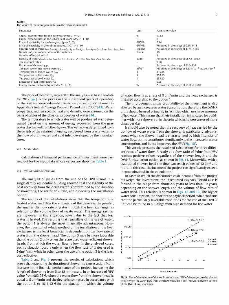
Table 2 and Fig. 9 present the results of calculations whichrove that extending the duration of showering causes a significant
ncrease in the financial performance of the project. Increasing the
ength of showering from 5 to 12 min results in an increase of NPValue from 953.98 D, when the water flow from the shower head isqual to 5 dm3/min and the device is connected in accordance withhe option 2, to 1816.12 D for the situation in which the volume
K 283.15– 0.95W Assumed in the range of 5100–11,600
of water flow is at a rate of 9 dm3/min and the heat exchanger isinstalled according to the option 1.
The improvement in the profitability of the investment is alsoaffected by an increase in water consumption, therefore the DWHRunits should be used primarily in facilities which use large amountsof hot water. This means that their installation is indicated for build-ings with more showers or in those in which showers are used moretimes per day.
It should also be noted that the recovery of heat carried by theoutflow of waste water from the shower is particularly advanta-geous when the shower head is characterized by high intensity ofwater flow, as this contributes significantly to the increase in waterconsumption, and hence improves the NPV (Fig. 10).
This article presents the results of calculations for three differ-ent rates of water flow. Already at a flow ratio of 9 dm3/min NPVreaches positive values regardless of the shower length and theDWHR installation option, as shown in Fig. 11. Meanwhile, with atraditional shower head the flow can reach values of 12 dm3 andmore. In this case, the income of the project can significantly exceedincome obtained in the calculation.
In cases in which the discounted cash incomes from the projectoutweigh the investment, the Discounted Payback Period DPP isformed in the range from about 2.5 years to less than 10 years,depending on the shower length and the volume of flow rate ofwater used. This relation is shown in Figs. 12 and 13. The higher
Fig. 9. Plot of the relation of the Net Present Value NPV of the project to the showerlength when the water flow from the shower head is 7 dm3/min, for different optionsof the DWHR unit assembly.
8 D. Słys, S. Kordana / Energy and Buildings 71 (2014) 1–11
Table 2Summary of the results of calculations for different durations of showering.
Parameters Variant Value
Shower length = 5 minWater flow from the showerhead (dm3/min) 5 7 9
Net Present Value NPV (D) 1 −136.19 117.55 332.182 −283.11 −42.79 130.803 −248.77 −78.97 123.36
D. Słys, S. Kordana / Energy and Buildings 71 (2014) 1–11 9
Fou
hsdhiwsmd
Flo
Fos
ig. 10. Plot of the relation of the Net Present Value NPV of the project to the ratef water flow from the shower during a five-minute shower for a variety of DWHRnit installation options.
On the basis of the calculations it was found that in the averageousehold, in which 35 dm3 of water are consumed during eachhower, the profitability of using the DWHR unit depends on theuration of the shower and the flow rate of water from the showeread, which makes it impossible to exactly determine whether the
nvestment should be carried out. The economic benefits increaseith decreasing water flow rate, which is equivalent to the exten-
ion of the duration of showering. The NPV is also affected by theethod of mounting the heat exchanger. Calculation results for
ifferent options of the use of the DWHR unit, when showering
ig. 11. Plot of the relation of the Net Present Value NPV of the project to the showerength for different values of the flow rate of water from the shower head for theption 1.
ig. 12. Plot of the relation of Net Present Value NPV of the project to the time ofperation of the system for different shower lengths when the water flow from thehower head is 7 dm3/min for the option 3.
Fig. 13. Plot of the relation of the Net Present Value NPV of the project to the timeof operation of the system for different values of the flow rate of water from theshower head when showering time is 5 min, for the option 1.
consumes 35 dm3 of water, are summarized in Table 3. They showthat the NPV reaches values in a range from −153.20 D when theunit is installed in accordance with the mounting option 3 and theshower length is 3.5 min, to 195.49 D, when the shower length isequal to 7 min and the heat exchanger is connected according tothe option 1. In the latter case, the Discounted Payback Period DPPwill be less than 8 years and the IRR is equal to 12.11%.
For some options of the use of the system of the heat recoveryfrom the wastewater discharged from the shower, the assessmentof project profitability was further supplemented by sensitivityanalysis. To this effect the NPV for various levels of percentagechanges in electricity prices and the amount of investment weredetermined, and the results were plotted on graphs shown inFigs. 14 and 15, thus obtaining the sensitivity curves.
Fig. 14 shows the results of the analysis for a situation where theuse of water during showering is 35 dm3 and the device is mountedunder the option 1. The safety margin for electricity prices in thiscase is −10.86%, while for the investment is equal to 12.18%. Therisk of investment failure is therefore high. It is unlikely that theprice of electricity in Poland and around the world will be reduced,what is associated with the need to purchase permits to emit green-house gases, but the capital expenditure may rise, especially for acomplex installation of the device in an existing facility or in caseof transportation costs unforeseen in the calculation. This is dueto the fact that the devices described are available only in certaincountries.
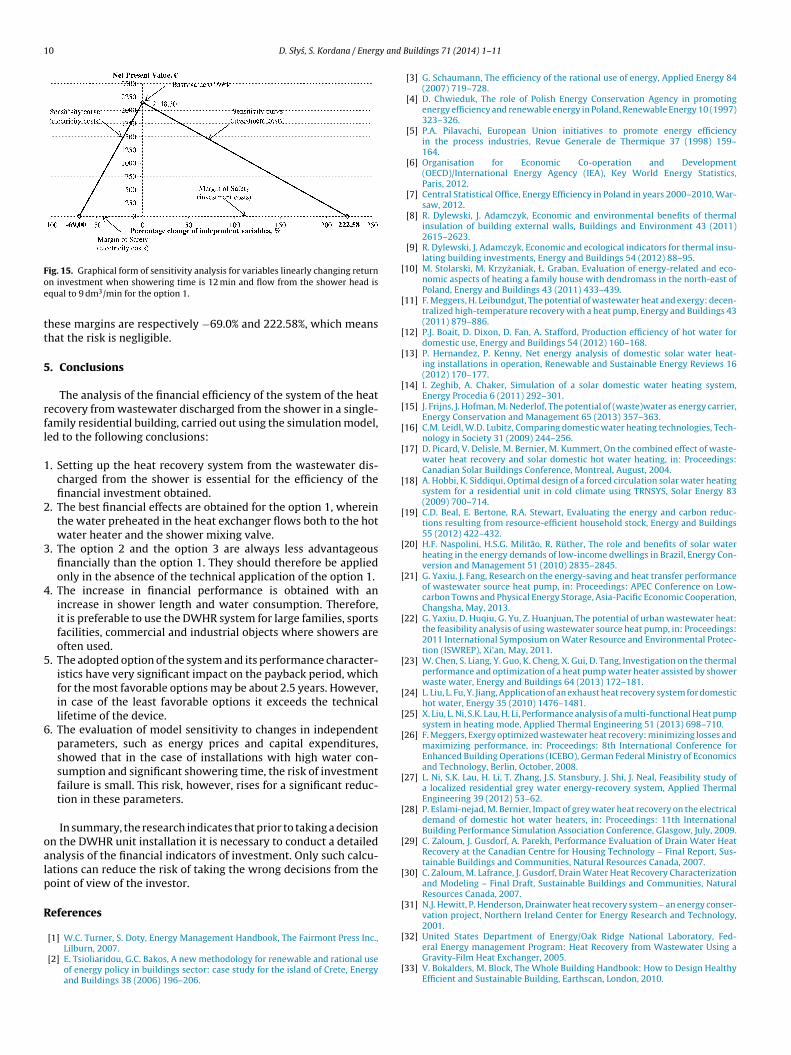
The financial risk of the project decreases with increasing wateruse for showering. In the most preferred of the analyzed cases(Fig. 15), that is when 108 dm3 of water at 42 ◦C is consumed dur-ing each shower and the unit is installed according to the option 1,
Fig. 14. Graphical form of sensitivity analysis for variables linearly changing returnon investment when showering time is 5 min and flow from the shower head isequal to 7 dm3/min for the option 1.
10 D. Słys, S. Kordana / Energy and
Foe
tt
5
rfl
1
2
3
4
5
6
oalp
R
[
[
[
[
[
[
[
[
[
[
[
[
[
[
[
[
[
[
[
[
[
[
ig. 15. Graphical form of sensitivity analysis for variables linearly changing returnn investment when showering time is 12 min and flow from the shower head isqual to 9 dm3/min for the option 1.
hese margins are respectively −69.0% and 222.58%, which meanshat the risk is negligible.
. Conclusions
The analysis of the financial efficiency of the system of the heatecovery from wastewater discharged from the shower in a single-amily residential building, carried out using the simulation model,ed to the following conclusions:
. Setting up the heat recovery system from the wastewater dis-charged from the shower is essential for the efficiency of thefinancial investment obtained.
. The best financial effects are obtained for the option 1, whereinthe water preheated in the heat exchanger flows both to the hotwater heater and the shower mixing valve.
. The option 2 and the option 3 are always less advantageousfinancially than the option 1. They should therefore be appliedonly in the absence of the technical application of the option 1.
. The increase in financial performance is obtained with anincrease in shower length and water consumption. Therefore,it is preferable to use the DWHR system for large families, sportsfacilities, commercial and industrial objects where showers areoften used.
. The adopted option of the system and its performance character-istics have very significant impact on the payback period, whichfor the most favorable options may be about 2.5 years. However,in case of the least favorable options it exceeds the technicallifetime of the device.
. The evaluation of model sensitivity to changes in independentparameters, such as energy prices and capital expenditures,showed that in the case of installations with high water con-sumption and significant showering time, the risk of investmentfailure is small. This risk, however, rises for a significant reduc-tion in these parameters.
In summary, the research indicates that prior to taking a decisionn the DWHR unit installation it is necessary to conduct a detailednalysis of the financial indicators of investment. Only such calcu-ations can reduce the risk of taking the wrong decisions from theoint of view of the investor.
eferences
[1] W.C. Turner, S. Doty, Energy Management Handbook, The Fairmont Press Inc.,Lilburn, 2007.
[2] E. Tsioliaridou, G.C. Bakos, A new methodology for renewable and rational useof energy policy in buildings sector: case study for the island of Crete, Energyand Buildings 38 (2006) 196–206.
[
[
Buildings 71 (2014) 1–11
[3] G. Schaumann, The efficiency of the rational use of energy, Applied Energy 84(2007) 719–728.
[4] D. Chwieduk, The role of Polish Energy Conservation Agency in promotingenergy efficiency and renewable energy in Poland, Renewable Energy 10 (1997)323–326.
[5] P.A. Pilavachi, European Union initiatives to promote energy efficiencyin the process industries, Revue Generale de Thermique 37 (1998) 159–164.
[6] Organisation for Economic Co-operation and Development(OECD)/International Energy Agency (IEA), Key World Energy Statistics,Paris, 2012.
[7] Central Statistical Office, Energy Efficiency in Poland in years 2000–2010, War-saw, 2012.
[8] R. Dylewski, J. Adamczyk, Economic and environmental benefits of thermalinsulation of building external walls, Buildings and Environment 43 (2011)2615–2623.
[9] R. Dylewski, J. Adamczyk, Economic and ecological indicators for thermal insu-lating building investments, Energy and Buildings 54 (2012) 88–95.
10] M. Stolarski, M. Krzyzaniak, Ł. Graban, Evaluation of energy-related and eco-nomic aspects of heating a family house with dendromass in the north-east ofPoland, Energy and Buildings 43 (2011) 433–439.
11] F. Meggers, H. Leibundgut, The potential of wastewater heat and exergy: decen-tralized high-temperature recovery with a heat pump, Energy and Buildings 43(2011) 879–886.
12] P.J. Boait, D. Dixon, D. Fan, A. Stafford, Production efficiency of hot water fordomestic use, Energy and Buildings 54 (2012) 160–168.
13] P. Hernandez, P. Kenny, Net energy analysis of domestic solar water heat-ing installations in operation, Renewable and Sustainable Energy Reviews 16(2012) 170–177.
14] I. Zeghib, A. Chaker, Simulation of a solar domestic water heating system,Energy Procedia 6 (2011) 292–301.
15] J. Frijns, J. Hofman, M. Nederlof, The potential of (waste)water as energy carrier,Energy Conservation and Management 65 (2013) 357–363.
16] C.M. Leidl, W.D. Lubitz, Comparing domestic water heating technologies, Tech-nology in Society 31 (2009) 244–256.
17] D. Picard, V. Delisle, M. Bernier, M. Kummert, On the combined effect of waste-water heat recovery and solar domestic hot water heating, in: Proceedings:Canadian Solar Buildings Conference, Montreal, August, 2004.
18] A. Hobbi, K. Siddiqui, Optimal design of a forced circulation solar water heatingsystem for a residential unit in cold climate using TRNSYS, Solar Energy 83(2009) 700–714.
19] C.D. Beal, E. Bertone, R.A. Stewart, Evaluating the energy and carbon reduc-tions resulting from resource-efficient household stock, Energy and Buildings55 (2012) 422–432.
20] H.F. Naspolini, H.S.G. Militão, R. Rüther, The role and benefits of solar waterheating in the energy demands of low-income dwellings in Brazil, Energy Con-version and Management 51 (2010) 2835–2845.
21] G. Yaxiu, J. Fang, Research on the energy-saving and heat transfer performanceof wastewater source heat pump, in: Proceedings: APEC Conference on Low-carbon Towns and Physical Energy Storage, Asia-Pacific Economic Cooperation,Changsha, May, 2013.
22] G. Yaxiu, D. Huqiu, G. Yu, Z. Huanjuan, The potential of urban wastewater heat:the feasibility analysis of using wastewater source heat pump, in: Proceedings:2011 International Symposium on Water Resource and Environmental Protec-tion (ISWREP), Xi’an, May, 2011.
23] W. Chen, S. Liang, Y. Guo, K. Cheng, X. Gui, D. Tang, Investigation on the thermalperformance and optimization of a heat pump water heater assisted by showerwaste water, Energy and Buildings 64 (2013) 172–181.
24] L. Liu, L. Fu, Y. Jiang, Application of an exhaust heat recovery system for domestichot water, Energy 35 (2010) 1476–1481.
25] X. Liu, L. Ni, S.K. Lau, H. Li, Performance analysis of a multi-functional Heat pumpsystem in heating mode, Applied Thermal Engineering 51 (2013) 698–710.
26] F. Meggers, Exergy optimized wastewater heat recovery: minimizing losses andmaximizing performance, in: Proceedings: 8th International Conference forEnhanced Building Operations (ICEBO), German Federal Ministry of Economicsand Technology, Berlin, October, 2008.
27] L. Ni, S.K. Lau, H. Li, T. Zhang, J.S. Stansbury, J. Shi, J. Neal, Feasibility study ofa localized residential grey water energy-recovery system, Applied ThermalEngineering 39 (2012) 53–62.
28] P. Eslami-nejad, M. Bernier, Impact of grey water heat recovery on the electricaldemand of domestic hot water heaters, in: Proceedings: 11th InternationalBuilding Performance Simulation Association Conference, Glasgow, July, 2009.
29] C. Zaloum, J. Gusdorf, A. Parekh, Performance Evaluation of Drain Water HeatRecovery at the Canadian Centre for Housing Technology – Final Report, Sus-tainable Buildings and Communities, Natural Resources Canada, 2007.
30] C. Zaloum, M. Lafrance, J. Gusdorf, Drain Water Heat Recovery Characterizationand Modeling – Final Draft, Sustainable Buildings and Communities, NaturalResources Canada, 2007.
31] N.J. Hewitt, P. Henderson, Drainwater heat recovery system – an energy conser-vation project, Northern Ireland Center for Energy Research and Technology,2001.
32] United States Department of Energy/Oak Ridge National Laboratory, Fed-eral Energy management Program: Heat Recovery from Wastewater Using aGravity-Film Heat Exchanger, 2005.
33] V. Bokalders, M. Block, The Whole Building Handbook: How to Design HealthyEfficient and Sustainable Building, Earthscan, London, 2010.
34] A. McNabola, K. Shields, Efficient drain water heat recovery in horizontaldomestic shower drains, Energy and Buildings 59 (2013) 44–49.
35] L.T. Wong, K.W. Mui, Y. Guan, Shower water heat recovery in high-residentialbuildings of Hong-Kong, Applied Energy 87 (2010) 703–709.
36] A. Coopermann, J. Dieckamann, J. Brodrick, Drain Water Heat Recovery, ASHRAEJournal 11 (2011) 58–62.
37] A. Kimmels, Shower Heat Recovery: Overview of Commercially Available
DWHR Systems, Meander Heat Recovery, 2011.
38] R.A. Brealey, S.C. Myers, F. Allen, Principles of Corporate Finance, 10th edition,McGraw-Hill/Irwin, New York, 2011.
39] E.F. Brigham, M.C. Ehrhardt, Financial Management: Theory and Practice, 12thedition, Thomson South-Western, Mason, OH, 2008.
[
[
Buildings 71 (2014) 1–11 11
40] J.C. Van Horne, J.M. Wachowicz, Fundamentals of Financial Management, 13thedition, Prentice Hall/Pearson Education Limited, Harlow, 2009.
41] M.C. Ehrhardt, E. Brigham, Corporate Finance: A Focused Approach, 4th edition,South-Western Cengage Learning, 2011.
42] S.A. PGE Obrót, Taryfa dla energii elektrycznej na rok 2012 dla odbiorców zgrup taryfowych G (Electricity Tariff for year 2012 for Customers from Tariff
43] Ministry of Economy, Projection of demand for fuels and energy until 2030,Appendix 2 to draft Energy Policy of Poland until 2030, Warsaw, 2009.
44] S. Wisniewski, T.S. Wisniewski, Wymiana ciepła (Heat exchange),Wydawnictwa Naukowo-Techniczne, Warsaw, 2009.