30
| Date post: | 17-Mar-2018 |
| Category: |
Documents |
| Upload: | dangnguyet |
| View: | 241 times |
| Download: | 1 times |


Find Gemlock Grooved Products at these locations:
GEM FABRICATION CLEVELAND, NC RENTON, WA 10230 Statesville Road Cleveland, NC 27013 875 SW 7th Street • Renton, WA 98057 Tel: (800) 845-2023 • Fax: (800) 962-3471 Tel: (800) 270-2235 • Fax: (425) 228-0162 TAMPA, FL JACKSONVILLE, FL 1801-B Massaro Blvd. • Tampa, FL 33619 2463 Lloyd Road • Jacksonville, FL 32254 Tel: (813) 626-4904 • Fax: (813) 621-1964 Tel: (904) 712-1075 • Fax: (904) 712-1080 GLEN BURNIE, MD 6711 Baymeadow Drive, Ste E2 • Glen Burnie, MD 21060 Tel: (410) 787-2810 • Fax: (410) 787-2815LONG ISLAND PIPE SUPPLY GARDEN CITY, NY QUINCY, MA 586 Commercial Avenue • Garden City, NY 11530 210 Ricciuti Drive • Quincy, MA 02169 Tel: (516) 222-8008 • Fax: (516) 222-9234 Tel: (617) 472-4575 • Fax: (617) 472-1612 MASPETH, NY WESTVILLE, NJ 58-58 56th Street • Maspeth, NY 11378 1050 Broadway • Westville, NJ 08093 Tel: (718) 456-7877 • Fax: (718) 456-7852 Tel: (856) 742-9000 • Fax: (856) 742-1761 BROOKLYN, NY BRONX, NY 729 Hicks Street • Brooklyn, NY 11231 COMING Tel: (718) 669-7600 • Fax: (718) 669-7601 SOON!! ALBANY, NY SALEM, NH 60 Cohoes Avenue • Green Island, NY 12183 50B Northwestern Dr. Unit 6 • Salem, NH 03079 Tel: (518) 270-2159 • Fax: (518) 270-8384 Tel: (603) 685-3200 • Fax: (603) 685-3206 WINDSOR, CT PROVIDENCE, RI 1220 Kennedy Rd., Suite 2 • Windsor, CT 06095 1195B Broad Steet • Providence, RI 02905 Tel: (860) 688-1780 • Fax: (860) 688-1784 Tel: (401) 490-9670 • Fax: (401) 490-6272BRECCO CORP. BRECCO WEST BRECCO EAST 77 N. 45th Avenue, Ste #1• Phoenix, AZ 85043 1040 Broadway • Westville, NJ 08093 Tel: (800) 543-4194 • Fax: (602) 484-9248 Tel: (800) 543-4194 • Fax: (602) 484-9248
NEILL SUPPLY 700 Schuyler Avenue • Lyndhurst, NJ 07071 Tel: (201) 939-1100 • Fax: (201) 939-6095

CONTENTS.................................................................1
.........................................................................2....................................................................3
..............................................................4............................................................5
.................................................................6............................7-8
............9............10
............................................11......................12
....................................................13.............................14
................................................14.......................................................... 15
........................................................................16................................................17................................................18
.......................................................18.....................................................19
.................................................................19..................................20
..............................................................21......................................................................21
............................22....................................................23
.................................................................24..................................................................25
Grooved Piping SystemGemlock FeaturesRigid Coupling - Style 5Flexible Coupling - Style 12Reducing Coupling - Style 25Groove Flange - Style 14Mechanical Tee - Style 15 Grooved & Style 16 ThreadedGrooved Fittings - Short Pattern - Styles F105, F106, F107, F135, & F155Standard Grooved Fittings - Styles 100, 101, 102, 103, 110, & 150Reducer Tee - Short Pattern - Style 115Standard Reducer - Style 140 Concentric - Style 145 EccentricDrain Elbow - Style F100D & F105DConcentric Reducer Threaded - Style 140TM, 140TFFlange Adapters - Style F190, F190TM90º Adapter Ell - Style 105TLTee Lock – Style 13Grooved Butterfly Valve - w/TamperPowerball 300 - Sprinkler Control ValveResidential Riser - Riser AssemblyShot Gun Riser - Riser Check ValveGrooved Check ValveGrooved Butterfly Valve - Style 700 - Lever/GearSuction Diffuser - Style 720Y Strainer - Style 760Pipe Preparation/ Pipe Grooving SpecificationsGasket Data - Standard IPS GasketsCross Reference ChartTerms and Conditions
1
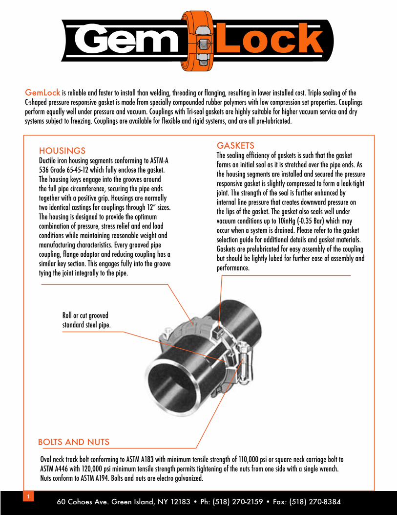
BOLTS AND NUTS
Roll or cut grooved standard steel pipe.
Oval neck track bolt conforming to ASTM A183 with minimum tensile strength of 110,000 psi or square neck carriage bolt to ASTM A446 with 120,000 psi minimum tensile strength permits tightening of the nuts from one side with a single wrench. Nuts conform to ASTM A194. Bolts and nuts are electro galvanized.
GemLock is reliable and faster to install than welding, threading or flanging, resulting in lower installed cost. Triple sealing of the C-shaped pressure responsive gasket is made from specially compounded rubber polymers with low compression set properties. Couplings perform equally well under pressure and vacuum. Couplings with Tri-seal gaskets are highly suitable for higher vacuum service and dry systems subject to freezing. Couplings are available for flexible and rigid systems, and are all pre-lubricated.
HOUSINGSDuctile iron housing segments conforming to ASTM-A536 Grade 65-45-12 which fully enclose the gasket.The housing keys engage into the grooves aroundthe full pipe circumference, securing the pipe endstogether with a positive grip. Housings are normallytwo identical castings for couplings through 12” sizes.The housing is designed to provide the optimumcombination of pressure, stress relief and end loadconditions while maintaining reasonable weight andmanufacturing characteristics. Every grooved pipecoupling, flange adaptor and reducing coupling has asimilar key section. This engages fully into the groovetying the joint integrally to the pipe.
GASKETSThe sealing efficiency of gaskets is such that the gasket forms an initial seal as it is stretched over the pipe ends. As the housing segments are installed and secured the pressure responsive gasket is slightly compressed to form a leak-tight joint. The strength of the seal is further enhanced by internal line pressure that creates downward pressure onthe lips of the gasket. The gasket also seals well under vacuum conditions up to 10inHg (-0.35 Bar) which may occur when a system is drained. Please refer to the gasket selection guide for additional details and gasket materials. Gaskets are prelubricated for easy assembly of the coupling but should be lightly lubed for further ease of assembly andperformance.
60 Cohoes Ave. Green Island, NY 12183 • Ph: (518) 270-2159 • Fax: (518) 270-8384

2
FEATURES
REDUCED COSTS
RELIABILITY
EXPANSION AND CONTRACTION
NOISE AND VIBRATION
UNION TYPE JOINT
DEFLECTION AND MISALIGNMENT
STRESS FREE JOINT
RIGIDITY
Coupling assembly is quick andeasy. Minimal training required. Thesystem is free from contaminatessuch as weld slag and pipe dope.Installation costs are controllableand estimates are more precise.
Couplings can be disassembledeasily permitting maintenance andservicing of the piping system. It willfacilitate periodic rotation of pipe todistribute internal wear from slurriesor other abrasive media.
The couplings engage the pipe aroundthe entire circumference and restrainthe pipe ends from separation dueto pressure and other forces, up tothe maximum coupling rated workingpressure.
Precise location of pipe openingsthrough walls and floors is unnecessary.Long radius curves may be designed with fewer elbows. Useful for providing pitch for drainage. Facilitates laying pipe on rough or uneven terrain.
Provides linear movement at eachjoint. Allows pipe expansion andcontraction. Suitable for hot and coldwater lines and dual temperaturesystems.
Flexibility of the joint reduces oreliminates stresses from settlementof burried pipe or induced by seismictremors.
Slight gap between pipe ends isolatesnoise and vibration. Resilient gasketalso helps to absorb noise andvibration. Often permits eliminationof noise suppression devices.
Couplings available for rigidity atvalves, equipment or mechanicalrooms. Couplings grip pipe to providea rigid system used with standardgroove specifications.

3
Pipe MaxWorking Pressure
(psi)*
Allow Pipe End
Separation(In.)§
Dimensions (In.) Approx.WeightEach(lb.)
NominalSize
Actual SIze(In.) A B C
1¼” 1.660 400 0.10 2.535 3.897 1.732 1.5
1½” 1.900 400 0.10 2.803 3.858 1.732 1.7
2” 2.375 400 0.10 3.283 5.00 1.732 1.9
2½” 2.875 400 0.10 3.842 5.433 1.732 1.9
3” 3.500 400 0.10 4.574 6.535 1.772 2.4
4” 4.500 400 0.16 5.416 7.598 1.889 3.2
5” 5.563 300 0.16 6.771 8.818 1.889 4.5
6” 6.625 300 0.16 7.874 9.921 1.889 5.8
10”* 10.75 300 0.19 11.25 15.875 2.500 16.60
8” 8.625 300 0.19 10.11 12.367 2.362 10.8
NOTES:Allowable pipe end separation is for cut groove pipe for roll groove, figures will be one-half of the values listed at time of initial pressurization.� – Bolts and Nuts are galvanized. * – Maximum pressure including surges and maximum end loads from all internal and external forces, towhich a joint could be subject under normal working conditions. This rating provides a nominal safety factor of 1.5 times working pressure basedon standard weight steel pipe. Maximum working pressure may be subjected to a one time field test of 1.5 times the figures indicated. Refer to installations and groove specifications when assembling any grooved product. EPDM gasket is supplied as standard. For other gaskets contact us.
C
A
B
RIGID COUPLING - STYLE 5• Provides joint rigidity, for the support and hanging requirements of ANSI B31.1 Power Piping Code; ANSI B31.9 Building Service Pipe Code and NFPA 13 Sprinkler Systems• Tongue and groove arrangements in housings do not permit expansion, contraction or deflection• Available with hot dipped galvanized coatings as optional• Supplied with pre-lubed gasket
60 Cohoes Ave. Green Island, NY 12183 • Ph: (518) 270-2159 • Fax: (518) 270-8384
UL Listed Under File No. EX15592
* Standard Weight Coupling

4
Pipe MaxWorking Pressure
(psi)*
AllowPipe End
Separation(in.)§
Max Deflection fromCenter Line §
Dimensions (In.) Approx.WeightEach(lb.)Nominal
SizeActual Size
(In.)Per Coup.
Deg.Pipe(In.) A B C
1¼” 1.660 400 0.10 4˚-19’ 0.90 2.535 3.897 1.732 1.3
1½” 1.900 400 0.10 3˚-46’ 0.79 2.803 4.527 1.732 1.5
2” 2.375 400 0.10 3˚-1’ 0.62 3.283 5.00 1.732 1.7
2½” 2.875 400 0.10 2˚-29’ 0.52 3.842 5.433 1.732 2.0
3” 3.500 400 0.10 2˚-3’ 0.43 4.574 6.535 1.772 2.6
4” 4.500 400 0.16 3˚-11’ 0.67 5.614 7.598 1.889 4.1
5” 5.563 300 0.16 2˚-35’ 0.54 6.771 8.818 1.889 5.7
6” 6.625 300 0.16 2˚-10’ 0.46 7.874 9.921 1.889 6.1
8” 8.625 300 0.19
10” * 10.75 300 0.19 0˚-95’ 0.13 12.91 16.54 2.52 21.5
1˚-40’ 0.34 10.71 12.637 2.362 11.9
FLEXIBLE COUPLING - STYLE 12• Provides joint flexibility required in some piping systems• Conforms to the requirements of ANSI B31.1 Power Piping Code; ANSI B31.9 Building Service Pipe Code and NFPA 13 Sprinkler Systems• Available with hot dipped galvanized coating as optional• Supplied with pre-lubed gasket
C
A
B
NOTES:Allowable pipe end separation is for cut groove pipe for roll groove, figures will be one-half of the values listed at time of initial pressurization.� – Bolts and Nuts are galvanized. * – Maximum pressure including surges and maximum end loads from all internal and external forces, towhich a joint could be subject under normal working conditions. This rating provides a nominal safety factor of 1.5 times working pressure basedon standard weight steel pipe. Maximum working pressure may be subjected to a one time field test of 1.5 times the figures indicated. Refer to installations and groove specifications when assembling any grooved product. EPDM gasket is supplied as standard. For other gaskets contact us.
*Standard weight coupling
UL Listed Under File No. EX15592

5
Pipe MaxWorking Pressure
(psi)*
AllowPipe End
Separation(in.)§
Max Deflection fromCenter Line §
Dimensions (In.) Approx.WeightEach(lb.)Nominal
SizePer Coup.
Deg.Pipe(In.) A B C
1½” x 1¼” 300 0.12 1˚-53’ 0.40 2.88 4.55 1.77 2.2
2” x 1¼” 300 0.12 1˚-53’ 0.40 3.543 5.079 1.85 2.2
2” x 1½” 300 0.12 1˚-33’ 0.40 3.543 5.079 1.85 2.0
2½” x 2” 300 0.12 1˚-33’ 0.32 3.976 5.394 1.8 3.1
3” x 2” 300 0.12 1˚-17’ 0.26 4.724 6.45 1.89 4.0
3” x 2½” 300 0.12 1˚-17’ 0.26 4.72 6.457 1.89 3.7
4” x 2” 300 0.25 2˚-38’ 0.55 5.906 7.677 1.929 6.4
4” x 2½” 300 0.25 2˚-38’ 0.55 5.906 7.677 1.929 6.2
4” x 3” 300 0.25 2˚-38’ 0.55 5.906 7.677 1.929 5.5
5” x 4” 300 0.25 2˚-5’ 0.44 6.969 8.74 1.909 10.8
6” x 4” 300 0.25 1˚-44’ 0.38 7.992 9.252 1.969 11.0
8” x 6” 300 0.25 1˚-15’ 0.26 10.394 12.32 2.362 18.5
Size(In.)
Flow Reducing Flow Expanding
CLValue
Equivalent PipeLength(Smaller Dia.)
CLValue
Equivalent PipeLength(Smaller Dia.)
6” x 4” 0.16 4.5 ft 0.08 2.3 ft
5” x 4” 0.14 3.0 ft 0.14 3.3 ft
4” x 3” 0.37 6.0 ft 0.15 2.5 ft
3” x 2½” 0.30 3.8 ft 0.19 2.5 ft
3” x 2” 0.50 5.5 ft 0.30 3.5 ft
2½” x 2” 0.18 1.9 ft 0.09 1.0 ft
2” x 1½” 0.25 1.9 ft 0.23 2.0 ft
HEAD LOSS
In above table, CL = 2GHL
V 2
HL = Head Loss in feet
V = Velocity in smaller pipe in feet/sec.
G = Acceleration due to gravity = 32.2 feet/sec.
REDUCING COUPLING - STYLE 25• Replaces two couplings and in-line reducer (concentric or eccentric)• Available with hot dipped galvanized coating
C
A
B
60 Cohoes Ave. Green Island, NY 12183 • Ph: (518) 270-2159 • Fax: (518) 270-8384
NOTES:Allowable pipe end separation is for cut groove pipe for roll groove, figures will be one-half of the values listed at time of initial pressurization.� – Bolts and Nuts are galvanized. * – Maximum pressure including surges and maximum end loads from all internal and external forces, towhich a joint could be subject under normal working conditions. This rating provides a nominal safety factor of 1.5 times working pressure basedon standard weight steel pipe. Maximum working pressure may be subjected to a one time field test of 1.5 times the figures indicated. Refer to installations and groove specifications when assembling any grooved product. EPDM gasket is supplied as standard.
UL Listed Under File No. EX15592

6
.
Pipe Max Working Pressure
(psi)*
Number and Bolt Size
Sealing Surface (In.) Dimensions (In.) Approx.Wt.
Each(lb.)
NominalSize
Actual Size(In.)
X Min. Y Max. A B CANSI ANSI
2” 2.375 300 4⅝ x 2½ 3.09 2.42 8.110 4.763 0.866 3.0
2½” 2.875 300 4⅝ x 3 3.58 2.92 9.055 5.511 0.866 4.2
3” 3.500 300 4⅝ x 3 4.21 3.56 9.527 5.984 0.944 4.4
4” 4.500 300 8⅝ x 3 5.26 4.57 11.023 7.519 0.944 8.4
5” 5.563 300 8¾ x 3½ 6.41 5.65 12.795 8.503 0.964 9.0
6” 6.625 300 8¾ x 3½ 7.48 6.71 13.188 9.500 0.866 10.4
8” 8.625 300 8¾ x 3½ 9.58 8.70 16.311 11.751 1.181 19.8
GROOVED FLANGE - STYLE 14• Designed to connect ANSI Class 125 or 150 flanged components to a grooved piping system• Made of a ductile iron conforming to ASTM A-536. Every lot is metallurgically examined to insure compliance• Provided with EPDM rubber gasket as standard, suitable for -30˚F to 150˚F (-34˚C to 110˚C)• Available with hot dipped galvanized coating
A
C
Bx
Y
UL Listed Under File No. EX15592
10” 10.75 300 12⅞ x 3½ 11.91 11.18 19.50 14.375 1.181 23.4

7
Run Size(In.)
Outlet Size(In.)
MaxWorkingPressure
(psi)*
Hole Diameter Grooved Dimensions (In.) Threaded Dimensions (In.) Approx. Weight Each
Hole Saw(in.)
Max Perm.(In.)
Grvd.A
Thrd.A B CB C
Grvd.lb.
Thrd.lb.
2
1/2 300 1.50 1.63 - 2.36 2.71 2.77 - 2.5
3/4 300 1.50 1.63 - 2.36 2.71 2.87 - 2.2
1 300 1.50 1.63 - 2.36 2.71 4.57 - 2.4
1-1/4 300 1.75 1.81 2.32 2.71 4.57 2.36 2.71 4.57 2.5 2.5
1-1/2 300 1.75 1.81 2.32 2.71 4.57 2.36 2.71 4.57 2.5 2.5
2½
1/2 300 1.50 1.63 - 2.76 3.03 5.67 - 3.5
3/4 300 1.50 1.63 - 2.76 3.03 5.67 - 3.3
1 300 1.50 1.63 -
-
-
-
-
-
-
-
-
-
-
-
-
2.76 3.03 5.67 - 3.3
1-1/4 300 2.00 2.13 3.16 2.76 5.67 2.76 3.27 5.67 - 3.5
1-1/2 300 2.00 2.13 3.16 2.76 5.67 2.76 3.27 5.67 - 3.5
3
1/2 300 1.50 1.63 - 3.23 3.03 5.98 - 4.0
3/4 300 1.50 1.63 -
-
-
-
-
- -
- -
3.23 3.03 5.98 - 3.9
1 300 1.50 1.63 2.76 3.07 5.98 3.23 3.03 5.98 - 3.9
1-1/4 300 2.00 2.13 2.76 3.23 5.98 3.23 3.27 5.98 4.2 4.2
1-1/2 300 2.00 2.13 2.76 3.58 5.98 3.23 3.62 5.98 4.2 4.2
2 300 2.50 2.63 3.23 2.40 5.98 3.23 3.90 5.98 4.2 4.3
4
1/2 300 1.50 1.63 - 3.43 7.25 6.77 - 5.3
3/4 300 1.50 1.63 - 3.43 7.25 6.77 - 5.1
1 300 1.50 1.63 3.43 3.03 6.77 - 4.9
1-1/4 300 2.00 2.13 3.66 3.27 7.32 3.43 3.27 6.77 5.4 5.1
1-1/2 300 2.00 2.13 3.66 3.62 7.32 3.43 3.62 6.77 4.8 5.1
2 300 2.50 2.63 3.66 3.82 7.40 3.43 3.81 6.77 5.1 4.8
2-1/2 300 3.00 3.05 3.66 4.41 7.40 3.43 4.41 6.77 5.3 5.1
3 300 3.50 3.63 3.66 4.80 7.40 3.43 4.80 6.77 6.4 6.4
MECHANICAL TEES - STYLE 15 GROOVED & STYLE 16 THREADED• Mechanical Branchlet provides a direct branch connection at any location along the pipe run without welding. A hole cut along the center line of pipe will receive the hole locator collar to secure the outlet. A pressure responsive gasket molded to suit the run pipe insures leak tight joints. Cross type connections can be made utilizing upper housings only. Available with hot dipped galvanized coating.
STYLE 15
A
BC
STYLE 16
A
BC
A
60 Cohoes Ave. Green Island, NY 12183 • Ph: (518) 270-2159 • Fax: (518) 270-8384
UL Listed UnderFile No. EX15592
- - -

8
OUTLETSIZE
NominalSize(In.)
CvValues
Equiv. Feet of Pipe
Grvd.FemaleThrd.
½ 15 - 2.0
¾ 18 - 4.0
1 22 - 5.0
1¼ 39 5.5 6.0
1½ 52 7.0 8.0
2 87 9.0 10.5
2½ 117 11.0 12.5
3 173 13.5 15.5
4 346 20.0 22.0
PERFORMANCE DATA
Cross Configuration
STYLE 15
A
BC
STYLE 16
A
BC
A
MECHANICAL TEES - STYLE 15 GROOVED & STYLE 16 THREADED• Mechanical Branchlet provides a direct branch connection at any location along the pipe run without welding. A hole cut along the center line of pipe will receive the hole locator collar to secure the outlet. A pressure responsive gasket molded to suit the run pipe insures leak tight joints. Cross type connections can be made utilizing upper housings only.
NOTES:� – Bolts and Nuts are galvanized. * – Maximum pressure including surges and maximum end loads from all internal and external forces, towhich a joint could be subject under normal working conditions. This rating provides a nominal safety factor of 1.5 times working pressure basedon standard weight steel pipe. Maximum working pressure may be subjected to a one time field test of 1.5 times the figures indicated. Refer to installations and groove specifications when assembling any grooved product. EPDM gasket is supplied as standard. For other gaskets contact us.
Run Size(In.)
Outlet Size(In.)
MaxWorkingPressure
Hole Diameter Grooved Dimensions (In.) Approx. Weight Each
Hole Saw(in.)
Max Perm.(In.) A
Threaded Dimensions (In.)
AB CGrvd.
lb.Thrd.
lb.
5
1¼
1½
2½
6
1¼
1½
2½
82½
300 2.00 2.13 4.21 3.00 8.66 3.94 3.27 8.27 6.0 6.8
300 2.00 2.13 4.21 3.40 8.66 3.94 3.62 8.27 6.2 6.6
2 300 2.50 2.63 4.21 3.82 8.66 3.94 3.82 8.27 6.6 6.8
300 2.75 2.88 4.21 4.41 8.66 3.94 4.41 8.27 7.5 7.9
3 300 3.50 3.63 4.21 4.80 8.66 3.94 4.80 8.27 8.3 8.2
300 2.00 2.13 5.04 3.29 9.72 4.61 3.27 8.66 8.2 7.7
300 2.00 2.13 5.04 3.62 9.72 4.61 3.62 8.66 7.5 7.9
2 300 2.50 2.63 5.04 3.86 9.72 4.61 3.82 8.66 7.7 8.2
300 3.25 3.35 5.04 4.76 9.72 4.61 4.41 8.66 7.7 8.3
3 300 3.50 3.63 5.04 5.28 9.72 4.61 4.80 8.66 9.0 8.8
4 300 4.50 4.63 5.04 6.18 9.72 4.61 5.20 8.66 11.0 12.8
2 300 2.50 2.63 5.75 3.82 12.20 5.35 3.82 12.20 11.0 11.5
300 2.75 2.88 5.75 4.41 12.20 5.35 4.41 12.20 10.0 10.8
3 300 3.50 3.63 5.75 4.80 12.20 5.35 4.80 12.20 12.3 12.5
4 300 4.50 4.63 5.75 5.28t 12.20 5.35 5.20 12.20 12.6 13.2
B C
UL Listed Under File No. EX15592

9
Style F105 Style F135 Style F155
FLOW DATAFrictional Resistance (Expressed as equivalent Straight Pipe in Ft.)
Nominal Size(In.)
90˚ Elbow 45˚ Elbow Tee
STD F105 STD F106Branch Run
STD F107 STD F107
1 1.7 1.4 0.9 0.9 4.4 4.0 1.7 1.4
1¼ 2.3 1.8 1.2 1.0 5.8 4.2 2.3 1.8
1½ 2.7 2.5 1.3 1.3 6.7 5.5 2.7 2.5
2 3.4 3.2 1.7 1.6 8.6 8.2 3.4 2.5
2½ 4.1 3.9 2.1 2.0 10.3 10.1 4.1 3.9
3 5.1 4.8 2.6 2.4 12.8 12.5 5.1 4.8
4 6.7 6.5 3.4 3.2 16.8 16.0 6.7 6.5
5 8.4 8.4 4.2 4.0 21.0 20.5 8.4 8.2
6 10.1 10.0 5.1 4.8 25.3 24.0 10.1 9.6
8 13.3 13.0 6.7 6.5 33.3 33.0 13.3 13.0
Pipe 90˚ Elbow - No.F105 45˚ Elbow - No.F106 Equal Tee - No.F107 Cross - No.F135 End Cap - No.F155
Nominal Size (In.)
ActualSize (In.)
C to E(In.)
Approx. Wgt. Ea. (lb.)
C to E(In.)
Approx. Wgt. Ea. (lb.)
C to E(In.)
Approx. Wgt. Ea. (lb.)
C to E(In.)
Approx. Wgt. Ea. (lb.)
E to E(In.)
Approx. Wgt. Ea. (lb.)
1¼ 1.660 2.362 0.9 1.732 0.5 2.362 1.0 - - .866 0.4
1½ 1.900 2.362 1.1 1.732 0.9 2.362 1.5 - - .866 0.5
2 2.375 2.755 1.3 2.007 1.1 2.755 1.9 2.755 2.2 .866 0.6
2½ 2.875 3.00 2.0 2.007 1.8 3.00 2.6 3.00 3.3 .866 0.7
3 3.500 3.5 2.6 2.519 2.2 3.5 4.2 3.5 5.1 .866 1.1
4 4.500 4.00 5.1 2.992 4.0 4.00 6.6 4.00 7.5 .99 1.8
5 5.563 4.803 6.8 3.543 6.4 4.803 9.0 4.803 13.7 .99 2.9
6 6.625 5.50 12.8 3.74 9.3 5.50 20.9 5.5 19.7 .99 4.2
8 8.625 6.80 22.7 4.881 16.3 6.95 32.9 7.047 34.4 1.181 7.9
Flow data is based upon the pressure drop of Sch. 40 pipe.
GROOVED FITTINGS - SHORT PATTERNSTYLES F105, F106, F107, F135 & F155• Sized to improve flow• Designed to Fire Protection Industry standards for short patterned fittings• Rated for 300 lbs. • Made of durable, high-strength ductile iron conforming to ASTM A536; every lot is metallurgically tested for compliance• Available with hot dipped galvanized coating
Style F106 Style F107
E to E
C to E
60 Cohoes Ave. Green Island, NY 12183 • Ph: (518) 270-2159 • Fax: (518) 270-8384
C to E
C to E
C to E
C to E
C to E
C to EC to E
UL Listed Under File No. EX15591

10
FLOW DATAFrictional Resistance (Expressed as equivalent Straight Pipe in Ft.)
Nominal Size(In.)
Elbow Tee Nominal Size(In.)
Elbow Tee
90˚ Elbow
45˚ Elbow
Branch Run 90˚ Elbow
45˚ Elbow
Branch Run
1¼ 2.3 1.2 5.8 2.3 5 8.4 4.2 21.0 8.4
1½ 2.7 1.3 6.7 2.7 6 10.1 5.1 25.3 10.1
2 3.4 1.7 8.6 3.4 8 13.3 6.7 33.3 13.3
2½ 4.1 2.1 10.3 4.1 10 16.7 8.4 41.8 16.7
3 5.1 2.6 12.8 5.1 12 20.0 10.0 50.0 20.0
4 6.7 3.4 16.8 6.7
Pipe 90˚ Elbow - No.100
45˚ Elbow - No.101
22½˚ Elbow - No.102
11¼˚ Elbow - No.103
Equal Tee - No.110
End Cap - No.150
Nominal Size(In.)
Actual Size(In.)
C to E(In.)
Approx.Wgt. Ea.
(lb.)
C to E(In.)
Approx.Wgt. Ea.
(lb.)
C to E(In.)
Approx.Wgt. Ea.
(lb.)
C to E(In.)
Approx.Wgt. Ea.
(lb.)
C to E(In.)
Approx.Wgt. Ea.
(lb.)
E to E(In.)
Approx.Wgt. Ea.
(lb.)
1¼ 1.660 2.75 0.9 1.75 0.6 1.75 0.7 1.38 0.5 2.75 1.4 .866 0.12
1½ 1.900 2.75 1.1 1.75 1.0 1.75 0.8 1.38 0.7 2.75 1.8 .866 0.16
2 2.375 3.25 1.9 2.00 1.3 1.88 1.5 1.38 0.9 3.25 2.8 .866 0.26
2½ 2.875 3.75 3.0 2.00 2.2 2.00 1.9 1.50 1.5 3.75 4.4 .866 0.37
3 3.500 4.25 4.7 2.50 3.2 2.25 3.2 1.50 2.0 4.25 6.5 .866 0.52
4 4.500 5.00 7.8 3.00 5.5 2.87 5.3 1.75 3.3 5.00 11.8 .99 0.70
5 5.563 5.50 12.1 3.25 8.5 2.88 7.2 2.00 5.0 5.50 19.2 .99 1.14
6 6.625 6.50 16.5 3.50 12.5 3.13 11.4 2.00 7.4 6.50 24.0 .99 1.68
8 8.625 7.75 33.1 4.25 21.8 3.88 17.8 2.00 10.0 7.75 51.8 1.181 3.51
10 10.750 9.00 61.1 4.75 28.9 4.38 30.0 2.13 14.5 9.00 77.1 1.259 26.0
Flow data is based upon the pressure drop of Sch. 40 pipe.
STANDARD GROOVED FITTINGSSTYLES 100, 101, 102, 103, 110 & 150• All fittings are full flow design• Specifically for use in HVAC Systems• Made of durable, high-strength ductile iron conforming to ASTM A536; every lot is metallurgically tested for compliance• Available with hot dipped galvanized coating• Suitable for HVAC, plumbing, & fire protection systems
Style 100 Style 101
C to E
C to E
Style 102 Style 110
C to E
C to E
Style 103
E to E
Style 150
C to E
C to E
C to E
C to E
C to E
C to E
UL Listed Under File No. EX15591

11
FLOW DATAFrictional Resistance
(Expressed as equivalent Straight Pipe in Ft.)
Nominal Size(In.)
Reducer Tee Nominal Size(In.)
Reducer Tee
Branch Run Branch Run
1¼ 5.8 2.3 5 21.0 8.4
1½ 6.7 2.7 6 25.3 10.1
2 8.6 3.4 8 33.3 13.3
2½ 10.3 4.1 10 41.8 16.7
3 12.8 5.1
4 16.8 6.7
Flow data is based upon the pressure drop of Sch. 40 pipe.
Style 115TM and 115TF are available up to 8” run size and 2½”outlet size. Max working pressure of Threaded Tee is 300 psi.
6 x 6 x 5 5.60 30.96 ½ x 6½ x 2 5.60 26.46½ x 6½ x 2½ 5.60 26.56½ x 6½ x 3 5.60 24.06½ x 6½ x 4 5.60 25.08 x 8 x 1½ 7.05 33.08 x 8 x 2 7.05 33.5
8 x 8 x 2½ 7.05 39.08 x 8 x 3 7.05 33.68 x 8 x 4 7.05 47.48 x 8 x 5 7.05 48.38 x 8 x 6 7.05 49.88 x 8 x 6½ 7.05 50.5
10 x 10 x 2 8.46 84.910 x 10 x 2½ 8.46 83.810 x 10 x 3 8.46 82.710 x 10 x 4 8.46 79.410 x 10 x 5 8.46 78.910 x 10 x 6 8.46 78.310 x 10 x 8 8.46 77.2
Reducer Tee - No.115Add after part number the letters TF for internal or TM for external threaded outlet
Nominal Size(In.)
C to E(In.)
Approx.Wgt. Ea.
(lb.)
Nominal Size(In.)
C to E(In.)
Approx.Wgt. Ea.
(lb.)
2 x 2 x 1¼ 2.76 2.7 2 x 2 x 1½ 2.76 2.7
2½ x 2½ x 1 3.00 4.8 2½ x 2½ x 1¼ 3.00 4.8 2½ x 2½ x 1½ 3.00 5.12½ x 2½ x 2 3.00 5.1
3 x 3 x 1 3.38 5.83 x 3 x 1¼ 3.38 6.4 3 x 3 x 1½ 3.38 7.53 x 3 x 2 3.38 8.4
3 x 3 x 2½ 3.38 8.6 4 x 4 x 1 4.00 7.8
4 x 4 x 1¼ 4.00 9.6 4 x 4 x 1½ 4.00 10.2 4 x 4 x 2 4.00 10.4
4 x 4 x 2½ 4.00 11.4 4 x 4 x 3 4.00 11.6
5 x 5 x 1½ 4.80 14.3 5 x 5 x 2 4.80 14.5
5 x 5 x 2½ 4.80 15.2 5 x 5 x 3 4.80 15.4 5 x 5 x 4 4.80 16.1
6 x 6 x 1½ 5.60 24.0 6 x 6 x 2 5.60 26.4
6 x 6 x 2½ 5.60 26.5 6 x 6 x 3 5.60 26.5 6 x 6 x 4 5.60 29.3
REDUCER TEE - SHORT PATTERN - STYLE 115• All fittings are full flow design• Made of durable, high-strength ductile iron conforming to ASTM A536; every lot is metallurgically tested for compliance• Available with hot dipped galvanized coating
C to E
C to EC to E
Style 115
C to E
C to EC to E
Style 115TM
C to E
C to EC to E
Style 115TF
60 Cohoes Ave. Green Island, NY 12183 • Ph: (518) 270-2159 • Fax: (518) 270-8384
UL Listed Under File No. EX15591

12
ECCENTRIC REDUCER - STYLE 145
Style 140
Concentric Reducer - No.140
Nominal Size(In.)
E to E(in.)
Approx.Wgt. Ea.
(lb.)
Nominal Size(In.)
E to E(in.)
Approx.Wgt. Ea.
(lb.)
1¼ x 1 2.50 0.6 5 x 2½ 4.02 4
1½ x 1 2.50 0.8 5 x 3 4.02 4
2 x 1 2.50 0.7 5 x 4 4.02 4
2 x 1¼ 2.50 1.2 6 x 2 4.02 4
2 x 1½ 2.50 1.0 6 x 2½ 4.02 4
2½ x 1 2.50 3.6 6 x 3 4.02 4
2½ x 1¼ 2.50 3.3 6 x 4 4.02 4
2½ x 1½ 2.50 3.6 6 x 5 4.02 4
2½ x 2 2.50 3.9 8 x 3 5.00 9.3
3 x 1 2.50 1.3 8 x 4 5.00 10.4
3 x 1¼ 2.50 3.0 8 x 5 5.00 13.7
3 x 1½ 2.50 5.1 8 x 6 5.00 14.3
3 x 2 2.50 1.6 10 x 3 6.10 2.8
3 x 2½ 2.50 1.8 10 x 4 6.10 13.0
4 x 1 3.00 3.0 10 x 5 6.10 13.2
4 x 1¼ 3.00 4.6 10 x 6 6.10 14.1
4 x 1½ 3.00 6.9 10 x 8 6.10 16.5
4 x 2 3.00 2.4
4 x 2½ 3.00 2.7
4 x 3 3.00 3.2
5 x 2 4.02 4.6
Eccentric Reducer - No.145Add TF after part number for Internalor TM for External threaded outlet.
Nominal Size(In.)
E to E(in.)
Approx.Wgt. Ea.
(lb.)
2 x 1¼ 9 4.62 x 1½ 9 4.62½ x 2 9.5 1.43 x 1¼ 9.5 4.83 x 1½ 9.5 5.03 x 2 9.5 1.8
3 x 2½ 9.5 1.64 x 2 10 2.6
4 x 2½ 10 2.84 x 3 10 3.35 x 2 11 5.2
5 x 2½ 11 10.85 x 3 11 11.05 x 4 11 5.16 x 2 11.5 14.5
6 x 2½ 11.5 14.16 x 3 11.5 14.96 x 4 11.5 6.66 x 5 11.5 9.48 x 3 12 22.08 x 4 12 22.98 x 5 12 26.58 x 6 12 30.810 x 3 13 29.710 x 4 13 31.910 x 5 13 34.610 x 6 13 36.510 x 8 13 38
See Style 140TM and 140TF for threaded outlet.
STANDARD CONCENTRIC REDUCER - STYLE 140• All fittings are full flow design• Made of durable, high-strength ductile iron conforming to ASTM A536. Every lot is metallurgically tested for compliance• Available with hot dipped galvanized coating
E to E
E to E
Concentric Reducer - No.140
UL Listed Under File No. EX15591

13
Pipe Dimensions (In.) Approx.Wgt. Ea.
(lb.)NominalSize (In.)
ActualSize (In.)
C to E H
2 2.375 3.25 2.75 3.8
2½ 2.875 3.75 2.75 5.2
3 3.500 4.25 2.75 5.3
4 4.500 5.00 2.75 8.8
6 6.625 6.50 2.75 18.7
Pipe Dimensions (In.) Approx.Wgt. Ea.
(lb.)NominalSize (In.)
ActualSize (In.)
C to E H
2 2.375 2.75 2.00 1.0
2½ 2.875 3.00 2.00 1.7
3 3.500 3.50 2.00 2.5
4 4.500 4.00 2.00 5.3
6 6.625 5.50 2.00 13.9
FLOW DATAEquivalent Feet of Straight Pipe
NominalSize(In.)
90˚ Elbow
STD ShortPattern
2 3.5 3.2
2½ 4.3 3.9
3 5.0 4.8
4 6.8 6.5
6 10.0 10.0
Flow data is based upon the pressure drop of Sch. 40 pipe.
Drain Elbow-Standard - Style F100D Drain Elbow-Short Pattern - Style F105D
STANDARD DRAIN ELBOW - STYLE F100D & F105D• Provides 1” NPT drain required on some fire protection stand pipes• Smoother flow than fabricated segmented steel elbows• Made of ductile iron conforming to ASTM A536• Every lot is metallurgically tested to insure compliance• Available with hot dipped galvanized coating• Pressure rating of 300 lbs.
H
C to E
1" NPTor ISODrain
Drain Elbow-StandardStyle F100D
H
C to E
1" NPTor ISODrain
Drain Elbow-Short PatternStyle F105D
60 Cohoes Ave. Green Island, NY 12183 • Ph: (518) 270-2159 • Fax: (518) 270-8384
C to E
UL Listed Under File No. EX15591

14
NominalSize (In.)
ActualSize (In.)
E to E(In.)
Approx.Wgt. Ea.
(lb.)
2 2.375 4.0 6.6
2½ 2.875 4.0 8.8
3 3.500 4.0 11.0
4 4.500 6.0 19.8
5 5.563 6.0 22.0
6 6.625 6.0 28.6
8 8.625 6.0 43.0
10 10.750 8.0 60.5
E to E E to EStyle 190 Style 190TM
FLANGE ADAPTERS - STYLE F190 & STYLE F190 TM• Conforms to Class ANSI 125 lb. flange• Available with an external threaded or grooved end• Every lot is metallurgically tested for compliance• Available with hot dipped galvanized coating• Pressure ratings of fittings conform to those of Style 5, Style 12, and Style 25 couplings
CONCENTRIC REDUCER - STYLE 140 TF, TM Nominal
Size(In.)
E to E(In.)
Approx.Wgt. Each
(lb.)
2 x 1 2.5 1.39
2 x 1¼ 2.5 0.74
2 x 1½ 2.5 0.74
2½ x 1 2.5 1.14
2½ x 1¼ 2.5 1.14
2½ x 1½ 2.5 1.14
2½ x 2 2.5 1.14
3 x 1 2.5 1.59
3 x 1¼ 2.5 1.59
3 x 1½ 2.5 1.59
3 x 2 2.5 1.38
4 x 1 3 2.28
4 x 1¼ 3 2.28
4 x 1½ 3 2.28
4 x 2 3 2.28
6 x 1 4 6.92
6 x 1¼ 4 6.92
6 x 1½ 4 6.92
6 x 2 4 6.92
E to E
Style 140 TM
E to E
Style 140 TF
UL Listed Under File No. EX15591
UL Listed Under File No. EX15591

1560 Cohoes Ave. Green Island, NY 12183 • Ph: (518) 270-2159 • Fax: (518) 270-8384
1¼ x ½ 500 1.77 1.20
1¼ x ¾ 500 1.77 1.20
1¼ x 1 500 1.91 1.24
1½ x ½ 500 1.77 1.32
1½ x ¾ 500 1.77 1.32
1½ x 1 500 1.91 1.32
2 x ½ 500 1.75 1.57
2 x ¾ 500 1.77 1.57
2 x 1 500 1.91 1.63
2½ x ½ 500 1.75 1.75
2½ x ¾ 500 1.75 1.75
2½ x 1 500 1.91 1.81
NominalSizeInch
Max.WorkPress.psi BA
Dimensions in.
90º ADAPTER ELL- STYLE 105TL• Transitions From Grooved to Threaded Connection• Direct Connection to Sprinkler Heads• Available in Rust Inhibitive Black Paint & Galvanized Finish • UL/FM Rated for 500psi.
A
B
NPT
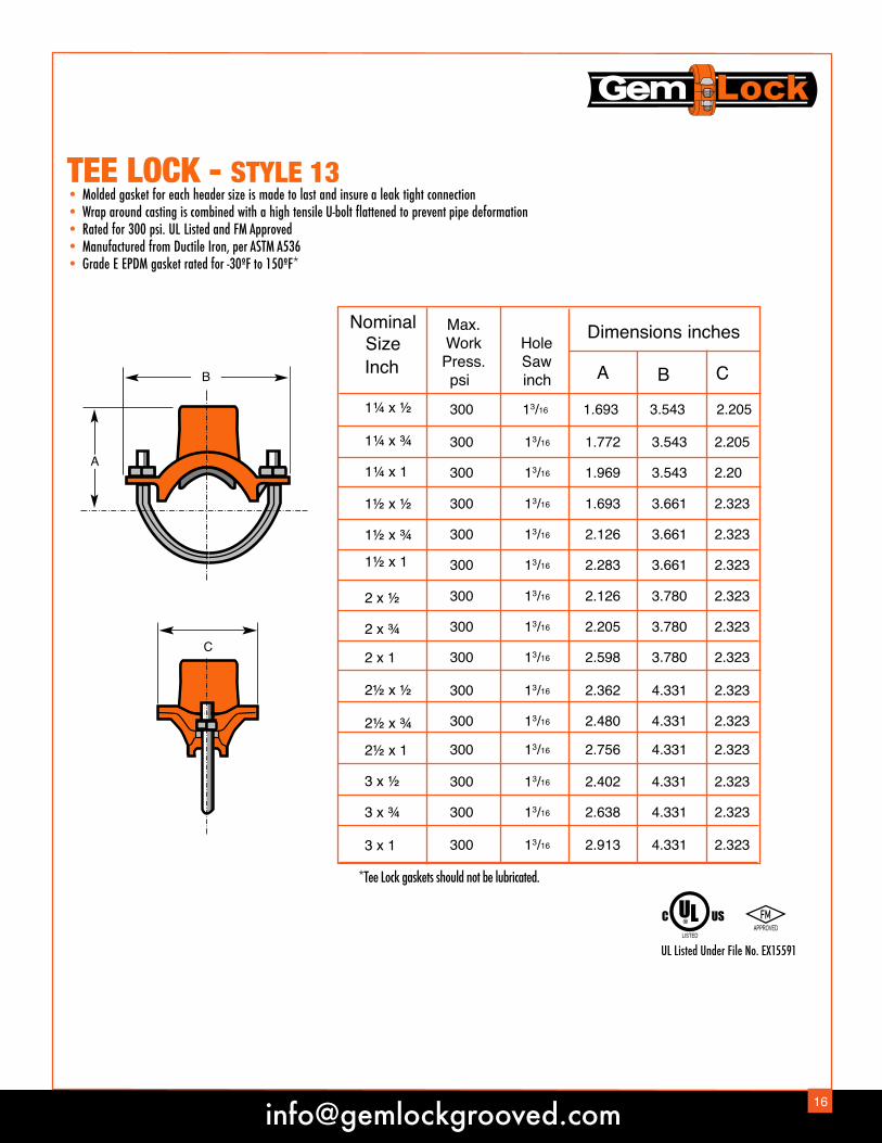
TEE LOCK - STYLE 13• Molded gasket for each header size is made to last and insure a leak tight connection• Wrap around casting is combined with a high tensile U-bolt flattened to prevent pipe deformation • Rated for 300 psi. UL Listed and FM Approved• Manufactured from Ductile Iron, per ASTM A536• Grade E EPDM gasket rated for -30ºF to 150ºF*
A
B
C
1¼ x ½ 300 13/16 1.693 3.543 2.205
1¼ x ¾ 300 13/16 1.772 3.543 2.205
1¼ x 1 300 13/16 1.969 3.543 2.20
1½ x ½ 300 13/16 1.693 3.661 2.32321.31½ x ¾ 300 13/16 2.126 3.661 2.323
1½ x 1 300 13/16 2.283 3.661 2.323
2 x ½ 300 13/16 2.126 3.780 2.323
2 x ¾ 300 13/16 2.205 3.780 2.323
2 x 1 300 13/16 2.598 3.780 2.323
2½ x ½ 300 13/16 2.362 4.331 2.323
2½ x ¾ 300 13/16 2.480 4.331 2.323
2½ x 1 300 13/16 2.756 4.331 2.323
3 x ½ 300 13/16 2.402 4.331 2.323
3 x ¾ 300 13/16 2.638 4.331 2.323
3 x 1 300 13/16 2.913 4.331 2.323
NominalSizeInch
Max.WorkPress.psi
HoleSawinch B CA
Dimensions inches
*Tee Lock gaskets should not be lubricated.
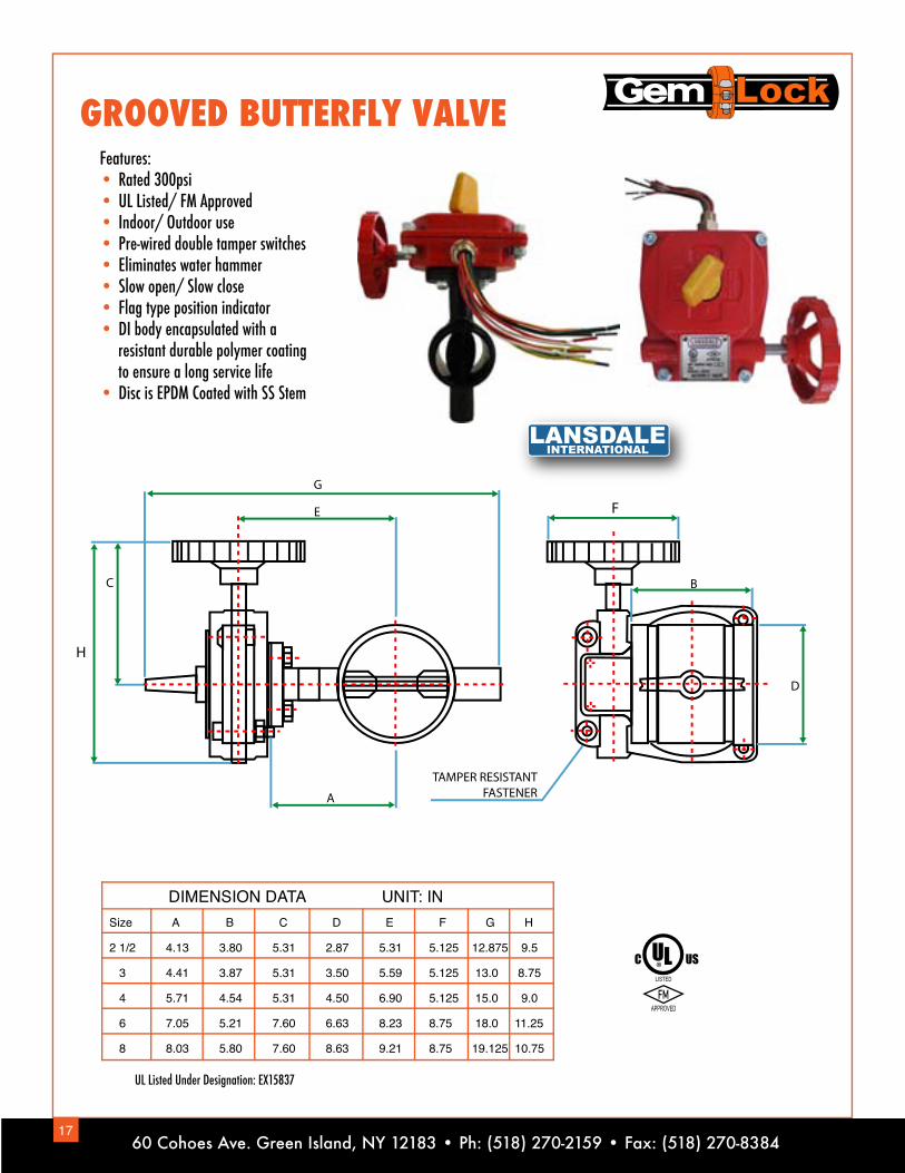
GROOVED BUTTERFLY VALVEFeatures:• Rated 300psi• UL Listed/ FM Approved• Indoor/ Outdoor use• Pre-wired double tamper switches • Eliminates water hammer• Slow open/ Slow close• Flag type position indicator • DI body encapsulated with a resistant durable polymer coating to ensure a long service life• Disc is EPDM Coated with SS Stem
Size A B C D E F G H
2 1/2 4.13 3.80 5.31 2.87 5.31 5.125 12.875 9.5
3 4.41 3.87 5.31 3.50 5.59 5.125 13.0 8.75
4 5.71 4.54 5.31 4.50 6.90 5.125 15.0 9.0
6 7.05 5.21 7.60 6.63 8.23 8.75 18.0 11.25
8 8.03 5.80 7.60 8.63 9.21 8.75 19.125 10.75
DIMENSION DATA UNIT: IN
E
C
D
A
B
G
TAMPER RESISTANTFASTENER
F
H
UL Listed Under Designation: EX15837
1760 Cohoes Ave. Green Island, NY 12183 • Ph: (518) 270-2159 • Fax: (518) 270-8384
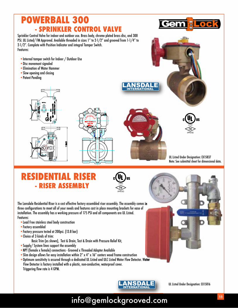
POWERBALL 300 - SPRINKLER CONTROL VALVE
RESIDENTIAL RISER - RISER ASSEMBLY
Sprinkler Control Valve for indoor and outdoor use. Brass body, chrome plated brass disc, and 300 PSI. UL Listed/ FM Approved. Available threaded in sizes 1” to 2-1/2” and grooved from 1-1/4” to 2-1/2”. Complete with Position Indicator and integral Tamper Switch.Features:
• Internal tamper switch for Indoor / Outdoor Use • Disc movement signaled • Elimination of Water Hammer • Slow opening and closing • Patent Pending
The Lansdale Residential Riser is a cost effective factory assembled riser assembly. The assembly comes in three configurations to meet all of your needs and features cast in place mounting brackets for ease of installation. The assembly has a working pressure of 175 PSI and all components are UL Listed.Features: • Lead Free stainless steel body construction • Factory assembled • Factory pressure tested at 200psi. (13.8 bar) • Choice of 3 kinds of trim: Basic Trim (as shown), Test & Drain, Test & Drain with Pressure Relief Kit, • Supply/ System lines support the assembly • NPT (female x female) connections - Grooved x Threaded Adapter Available • Slim design allows for easy installation within 2” x 4” x 16” centers wood frame construction • Optimum sensitivity is assured through a dedicated UL Listed and ULC Listed Water Flow Detector. Water Flow Detector is factory installed with a plastic, non-conductive, waterproof cover. Triggering flow rate is 4 GPM.
The Lansdale Residential Riser is a cost effective factory assembled riser assembly. The assembly comes in
Optimum sensitivity is assured through a dedicated UL Listed and ULC Listed Water Flow Detector. Water
UL Listed Under Designation: EX15816
UL Listed Under Designation: EX15837Note: See submittal sheet for dimensional data.
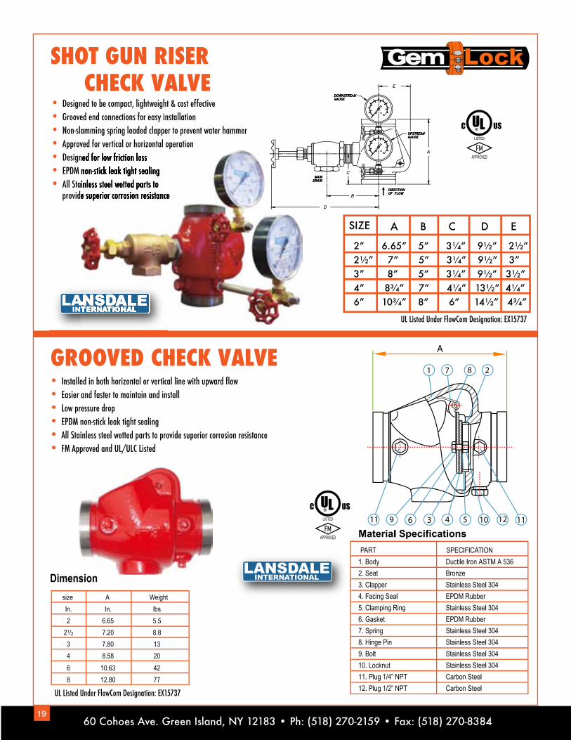
SHOT GUN RISER CHECK VALVE
GROOVED CHECK VALVE• Installed in both horizontal or vertical line with upward flow• Easier and faster to maintain and install• Low pressure drop• EPDM non-stick leak tight sealing• All Stainless steel wetted parts to provide superior corrosion resistance• FM Approved and UL/ULC Listed
• Designed to be compact, lightweight & cost effective• Grooved end connections for easy installation• Non-slamming spring loaded clapper to prevent water hammer• Approved for vertical or horizontal operation• Designed for low friction loss• EPDM non-stick leak tight sealing• All Stainless steel wetted parts to provide superior corrosion resistance
A
1 7 8 2
1112105436911
UL Listed Under FlowCom Designation: EX15737
UL Listed Under FlowCom Designation: EX15737
Designed for low friction lossEPDM non-stick leak tight sealingAll Stainless steel wetted parts to
provide superior corrosion resistance
2” 6.65” 5” 3¼” 9½” 2½”2½” 7” 5” 3¼” 9½” 3”3” 8” 5” 3¼” 9½” 3½”4” 8¾” 7” 4¼” 13½” 4¼”6” 10¾” 8” 6” 14½” 4¾”
A B C D ESIZE
1960 Cohoes Ave. Green Island, NY 12183 • Ph: (518) 270-2159 • Fax: (518) 270-8384
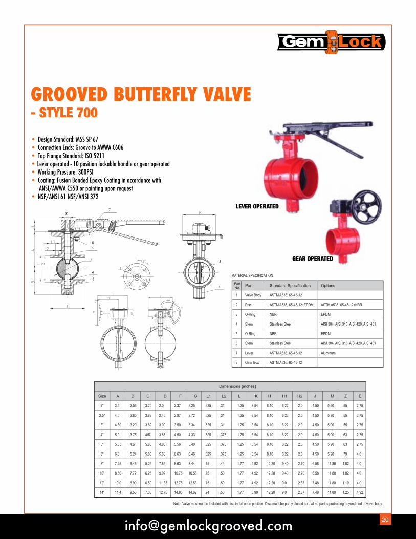
GROOVED BUTTERFLY VALVE- STYLE 700
• Design Standard: MSS SP-67• Connection Ends: Groove to AWWA C606• Top Flange Standard: ISO 5211• Lever operated - 10 position lockable handle or gear operated• Working Pressure: 300PSI• Coating: Fusion Bonded Epoxy Coating in accordance with ANSI/AWWA C550 or painting upon request• NSF/ANSI 61 NSF/ANSI 372
PartNo. Part Standard Specification Options
1 Valve Body ASTM A536, 65-45-12
2 Disc ASTM A536, 65-45-12+EPDM ASTM A536, 65-45-12+NBR
3 O-Ring NBR EPDM
4 Stem Stainless Steel AISI 304, AISI 316, AISI 420, AISI 431
5 O-Ring NBR EPDM
6 Stem Stainless Steel AISI 304, AISI 316, AISI 420, AISI 431
7 Lever ASTM A536, 65-45-12 Aluminum
8 Gear Box ASTM A536, 65-45-12
MATERIAL SPECIFICATION
z
Note: Valve must not be installed with disc in full open position. Disc must be partly closed so that no part is protruding beyond end of valve body.
Dimensions (inches)
Size A B C D F G L1 L2 L K H H1 H2 J M Z E
2" 3.5 2.56 3.20 2.0 2.37 2.25 .625 .31 1.25 3.54 8.10 6.22 2.0 4.50 5.90 2.75.55
2.5" 4.0 2.80 3.82 2.40 2.87 2.72 .625 .31 1.25 3.54 8.10 6.22 2.0 4.50 5.90 2.75.55
3" 4.30 3.20 3.82 3.00 3.50 3.34 .625 .31 1.25 3.54 8.10 6.22 2.0 4.50 5.90 2.75.55
4" 5.0 3.75 4.57 3.88 4.50 4.33 .625 .375 1.25 3.54 8.10 6.22 2.0 4.50 5.90 2.75.63
5" 5.55 4.37 5.83 4.83 5.56 5.40 .625 .375 1.25 3.54 8.10 6.22 2.0 4.50 5.90 2.75.63
6" 6.0 5.24 5.83 5.83 6.63 6.46 .625 .375 1.25 3.54 8.10 6.22 2.0 4.50 5.90 4.0.79
8" 7.25 6.46 5.25 7.84 8.63 8.44 .75 .44 1.77 4.92 12.20 9.40 2.70 6.58 11.80 4.01.02
10" 8.50 7.72 6.25 9.92 10.75 10.56 .75 .50 1.77 4.92 12.20 9.40 2.70 6.58 11.80 4.01.02
12" 10.0 8.90 6.50 11.83 12.75 12.53 .75 .50 1.77 4.92 12.20 9.0 2.87 7.48 11.80 4.01.10
14" 11.4 9.50 7.00 12.75 14.85 14.62 .94 .50 1.77 5.90 12.20 9.0 2.87 7.48 11.80 4.921.25
LEVER OPERATED
GEAR OPERATED

Part No. Part Standard Specification Options1 Valve Body ASTM A536, 65-45-12
2 Screen AISI 304 AISI 316
3 Rigid Coupling ASTM A536, 65-45-12
4 Cap ASTM A536, 65-45-125 Plug Malleable Iron Galvanized Bronze ASTM B584
SUCTION DIFFUSER- STYLE - 720
• Pump Protection Fitting: Reducing elbow, protective strainer, and flow straightener• Removable 20 mesh start up screen• Oversized diffuser screen• Creates uniform flow to pump• Working Pressure: 232 PSI• Working Temp: -14º F to 250º F• Internally and externally liquid epoxy painted or fusion bonded epoxy powder coated (FBE)• Avaliable from 2" thru 24" in straight and reducing sizes Note: For sizes and dimensional data please see the submittal sheet
L2
H1
L1
L
d
Part NameBodyCoverScreen
Stud & Nuts
MaterialCast IronCast Iron
Stainless SteelCarbon Steel
ASTM Spec.A126 Class BA126 Class B
AISI 304ASTM A307B
Y STRAINER- STYLE - 760 • Connection Ends: Groove to AWWA C606• Working Pressure: 300PSI • Working Temperature: 32ºF - 212ºF• Coating: Fusion Bonded Epoxy Coating in accordance with ANSI/AWWA C550 or painting upon request
OD
L
ød
4
532
1
SIZEDimensions(Inch)
L OD d2" 9.75 2.40 2.252.5" 10.75 2.90 2.723" 11.75 3.50 3.354" 14.25 4.50 4.335" 16.5 5.56 5.406" 18.5 6.63 6.508" 24.0 8.63 8.4510" 27.0 10.75 10.5612" 30.0 12.75 12.53
2160 Cohoes Ave. Green Island, NY 12183 • Ph: (518) 270-2159 • Fax: (518) 270-8384

1
Nominal Size(In.)
2Pipe Outside Diameter
OD(In.)
3Gasket Seat
A(In.)
4Groove Width
B(In.)
5Groove Diameter
C(In.)
6Groove Depth(Ref.)
D (In.)
7Min. AllowableWall Thickness
(In.)
8Max
Allowable Flare
Diameter(In.)Actual
SizeTolerance Roll
GrooveCut
GrooveActualSize
Toler. Roll Groove
Cut Groove
1 1.315 +0.013 -0.013 0.625 0.281 0.313 1.190 -0.015 0.063 0.065 0.133 1.43
1¼ 1.660 +0.016 -0.016 0.625 0.281 0.313 1.535 -0.015 0.063 0.065 0.140 1.77
1½ 1.900 +0.019 -0.019 0.625 0.281 0.313 1.775 -0.015 0.063 0.065 0.145 2.01
2 2.375 +0.024 -0.024 0.625 0.344 0.313 2.250 -0.015 0.063 0.065 0.154 2.48
2½ 2.875 +0.029 -0.029 0.625 0.344 0.313 2.720 -0.018 0.078 0.083 0.188 2.98
3 3.500 +0.035 -0.031 0.625 0.344 0.313 3.344 -0.018 0.078 0.083 0.188 3.60
4 4.500 +0.045 -0.031 0.625 0.344 0.375 4.334 -0.020 0.083 0.083 0.203 4.60
4½ 5.000 +0.050 -0.031 0.625 0.344 0.375 4.834 -0.020 0.083 0.095 0.203 5.10
5 5.563 +0.056 -0.031 0.625 0.344 0.375 5.395 -0.022 0.084 0.109 0.203 5.66
6 6.625 +0.063 -0.031 0.625 0.344 0.375 6.455 -0.022 0.085 0.109 0.219 6.73
8 8.625 +0.063 -0.031 0.750 0.469 0.438 8.441 -0.025 0.092 0.109 0.238 8.80
10 10.750 +0.063 -0.031 0.750 0.469 0.500 10.562 -0.027 0.094 0.134 0.250 10.92
12 12.750 +0.063 -0.031 0.750 0.469 0.500 12.531 -0.030 0.109 0.156 0.279 12.92
RunSize(In.)
BranchSize(In.)
Hole Diameter(In.)
+1/8 -0
WDimensions
(In.)
All ½, ¾, 1 1½ 3½
2 1¼, 1½ 1¾ 4
All 1¼, 1½ 2 4
All 2 2½ 4½
All* 2 ½* 2¾* 4¾
All 3 3½ 5½
All 4 4½ 5½
*4” x 2 ½- Hole Size 3”, 6” x 2½”- Hole Size 3¼”
PIPE PREPARATION FOR MECHANICAL BRANCHLETSCut or drill the hole in pipe. The hole diameter for each size is listed in the Table. Holes must be drilled on the centerline of the pipe. Remove the coupon and cutting chips. Check the pipe surface within 5/8” of the hole. This surface must be clean, smooth andfree from indentation or projection, which would affect proper sealing. The pipe around the entire circumference within the “W” dimension must be free from any dirt and scale, which might affect the sealing performance on the the pipe surface.
PIPE GROOVING SPECIFICATIONS
Column 1Nominal IPS pipe outside diameter.Column 2Maximum deviation from square cut ends for 1.25” thru 3” is 0.03”; for 4” thru 6” is 0.045” and for 8” and above is 0.06”.Column 3To provide a lock tight seal, the gasket seating area on pipe shall be free of roll marks, indentations, paint scale, dirt, chips, grease, rust and etc.Column 4Groove width. Groove bottom to be free from loose dirt, chips, rust and scales. Bottom of grooves to be radius and the vertical wall of grooves must provide at least 0.03” vertical side for proper assembly of couplings.
Column 5Groove outside diameter. The groove must be concentric to the pipe circumference. Groove must be within the diametertolerance indicated.Column 6Groove depth. For reference only. Refer to Column 5.Column 7Minimum allowable wall thickness to which the pipemay be roll grooved or cut grooved.Column 8Maximum allowable pipe and flare diameter.Measured at the most extreme pipe ends.

GASKET DATA Standard IPS Gaskets
GRADE E TTEMPERATURE
RANGE-30˚F to +230˚F-34˚C to +110˚C
-20˚F to +180˚F-29˚C to +82˚C
COMPOUNDEPDM
Conforming to ASTM D2000(2CA615A25B24F17Z)
NITRILE(BUNA - N)
GENERALSERVICE
RECOMMENDATIONS
Recommended for hot water service within the specified temperature range plus a variety of dilute acids, oil-free air and many chemical services. UL classified in accordance with ANSI/NSF 61 for cold -30˚F (-34˚C) and hot +230˚F (+110˚C) potable water service.Not recommended for petroleum services.
Recommended for petroleum products, air with oil vapors, vegetables and mineral oils within the specified temperature range.
Not recommended for hot water services over +150˚F (+66˚C) or hot dry air over +140˚F (+60˚C).
CHEMICALSERVICES
AcetaidehydeAcetic Acid up to 10%100˚F (38˚C)Acetic AnhydrideAcetoneAcetophenoneAcetyleneAlkalisAllyl Alcohol to 96%AlumsAluminum ChlorideAluminum FlourideAluminum HydroxideAluminum NitrateAluminum PhosphateAluminum SaltsAluminum SulfateAmmonia Gas, ColdAmmonia Gas, HotAmmonia, LiquidAmmonium CarbonateAmmonium FlourideAmmonium HydroxideAmmonium MetaphosphateAmmonium NitrateAmmonium Persulfateto 10%Ammonium SulfateAmmonium SulfideAmmonium ThictnateAmmonium ThioynateAmyl AcetateAmyl AlcoholAnilineAniline DyesAniline HydrochlorideAniline OilAntimony ChlorideAntimony TrichlorideArgon GasBarium CarbonateBarium ChlorideBarium HydroxideBenzaldehydeBenzoic AcidBenzyl AlcoholBenzyl BenzoateBleach, 12% Active CPBoraxBorddeaux MixtureBoric AcidButanol (see Butyl Alcohol)Butyl AcetateButyl Acetyl RicinoleateButyl AlcoholButyl “Cellosolve Adipate”Butyl PhenolButylene GlycolCalcium ChlorideCalcium Hydroxide (Lime)Calcium HypochloriteCalcium HypochlorideCalcium NitrateCalcium SulfideCarbotolCarbon Dioxide, DryCarbon Dioxide, WetCarbon MonoxideCaustic PotashCellosolve AcetateCellosolve (Alcohol Ether)Cellulose AcetateCellulube 220(Tri-Aryl-Phosphate)Cellulube Hydraulic Fluids
Chloric Acid to 20%Chlorine, WaterChloroacetic AcidChloroacetoneCitric AcidCopper FlourideCopper NitrateCopper SulfateCyclohexanoneDeionized WaterDibutyl PhialateDiethyl SewbacateDiethylene GlycolDioctyl PhthalateDiozaneDowtherm SR-1EthanolamineEthyl AcetoacetateEthyl AlcoholEthyl CelluloseEthyl “Cellusolve”Ethyl ChlorideEthyl OxalateEthylene ChlorohydrinEthylene GlycolFerric Chloride to 35%Ferric Chloride, SaturatedFerric HydroxideFluboric AcidFly AshFoamFormaldehydeFormic AcidFreon 134a, 176˚F (80˚C)Fumaric AcidFurfuryl AlcoholGlueGlycerinGlycerolGlycolGlycolic AcidHalonHexaldehydeHydrobromic Acid to 40%Hydrochloric Acid to 36%,75˚F (28.9˚C)Hydrocyamic AcidHydrogen Gas, ColdHydrogen Gas, HotHydrogen SulfideHydroxylamine SulfateHydrochlorous Acid, DiluteIsobutyl AlcoholIsopropyl AcetateIsopropyl AlcoholKetonesLead ChlorideLime and H2OMagnesium ChlorideMagnesium HydroxideMagnesium Sulfate
ASTM #3 OilAcetamideAcetonitrateAcetyleneAdipic AcidAlumsAluminum ChlorideAluminum FlourideAluminum NitrateAluminum OxychlorideAluminum SulfateAmmonium BiflourideAmmonium ChlorideAmmonium NitrateAmmonium PhosphateAmmonium SulfamateAmyl ChloronaphthaleneArsenic Acid to 75%Barium ChlorideBarium HydroxideBarium SulfideBlack Sulfate LiquorBlast Furnace GasBoric AcidButane GasButanol (See Butyl Alcohol)Butyl AlcoholButyl “Cellosolve Adipate”Butyl StearateButyleneCalcium AcetateCalcium BisulphateCalcium BisulphiteCalcium FluophosphateCalcium Hydroxide (Lime)Calcium SulfateCaliche LiquorsCarbitolCarbon Dioxide, DryCarbon Dioxide, WetChina Wood Oil, Tung OilChlorinated ParalineChrome AlumCoke Oven GasCopper ChlorideCopper CyanideCopper NitrateCopper SulfateCupric FluorideCupric SulfateDextrimDichloro-Difluoro-MethaneDichloro HexamineDiesel OilDiethyl EtherDiethylene GlycolDimethylamineDipentene (Terpene Hydrocarbon)Dipropylene GlycolDowtherm SR-1Ethyl AlcoholEthyl EtherEthyl SilicateEthylene DiamineEthylene Glycol FFerric Chloride to 35%Ferric SulfateFog OilFormaldehydeFormanideFreon 11, 130˚F (54˚C)Freon 12, 130˚F (54˚C)Freon 113, 130˚F (54˚C)Freon 114, 130˚F (54˚C)
Freon 134a, 176˚F (80˚C)FructoseFuel OilGasoline, RefinedGlueGlycerinGlycerolGlycolGreaseGreen Sulfate LiquorHeptaneHexaneHaxanol TertiaryHexyl AlcoholHexylene GlycolHydrofluosilicic AcidHydrogen Gas, ColdHydroquiconeIso Octane, 100˚F (38˚C)Isopropyl EtherJP-3JP-4JP-5KeroseneLauric AcidLavender OilLead AcetateLead SulfateLime and H2OLithium BromideLithium ChlorideLubricating Oil, RefinedLubricating Oil, SourLubricating Oilto 150˚F (66˚C)Magnesium ChlorideMagnesium HydroxideMagnesium SulphateMaleic AcidMalic AcidMercuric Chloride
Mercuric ChlorideMercuric CyanideMercuryMethyl Acetate Methyl Alcohol, MethanolMethyl Cellosolve (Ether)Methyl Ethyl KetoneMethyl Formate Methyl Isobutyl CarbinolMethyl Isobutyl KetoneNickel Chloride Nickel Nitrate Nickel Plating Solution 125°F (52°C)-Max. Nitric Acid, to 10%, 75°F-(24°C)-Max.
Mercuric CyanideMercury Methyl Alcohol, MethanolMethyl Isobutyl CarbinolMineral Oils Nickel Chloride Octyl Alcohol Olive Oil Phosphoric Acid, to 75% & 70°F (21°C)-Max.Photographic SolutionsPotassium BromidePotassium CarbonatePotassium ChloridePotassium ChromatePotassium CyanidePotassium FerricyanidePotassium FerrocyanidePotassium HydroxidePotassium IodidePotassium NitratePotassium SulphatePropyl Alcohol Propylene GlycolPyroguard “C” &-“D”Salicylic Acid Soda Ash,-Sodium Carbonate Sodium BicarbonateSodium BisulphateSodium Bisulphite (black liquor)Sodium BromideSodium ChlorateSodium ChlorideSodium CyanideSodium Metaphosphate
Nitric Acid, to 10%, 75°F-(24°C)-Max. Nitrous Oxide Oxalic Acid Ozone Phosphate EsterPhosphoric Acid, to 75% & 70°F (21°C)-Max. Potassium Bromide Potassium Carbonate Potassium Chloride Plating Solutions (gold, brass cadmium,copper, lead, silver, tin, zinc) Potassium CyanidePotassium FerricyanidePotassium FerrocyanidePotassium IodidePotassium NitratePotassium Permanganate, saturated, to 25%Potassium SulphatePropanol Propyl Alcohol Propylene GlycolPyroguard 55 Pyrrole Salicylic Acid Silver Cyanide Silver Nitrate Skydrol 500 Phosphate EsterSoda Ash,-Sodium CarbonateSodium Bicarbonate Sodium Bisulphate Sodium Bisulphite (black liquor) Sodium Bromide Sodium Chlorate Sodium ChlorideSodium CyanideSodium Hydroxide, to 50%Sodium Hypochlorite, to 20%Sodium MetaphosphateSodium Nitrate Sodium PeroxideSodium PhosphateSodium Silicate Sodium SulphideSodium Sulphite Solution, to 20%Sodium Thiosulphate, “Hypo”Stannous Chloride, to 15% Starch Sulphur Sulphuric Acid, to 25%, 150°F (66°C)-Max. Tributyl PhosphateTriethanolamine Trisodium Phosphate Urea Vinyl Acetate White Liquor Zinc Sulphate
Sodium Nitrate Sodium PhosphateSodium Silicate Sodium SulphideSodium Sulphite Solution, to 20%Sodium Thiosulphate, “Hypo” Soybean Oil Stannous Chloride, to 15%Starch Stearic Acid Sucrose SolutionsTriethanolamine Trisodium Phosphate Turpentine 158°F-(70°C)-Max. Urea Vegetable Oils Vinegar Zinc Sulphate
2360 Cohoes Ave. Green Island, NY 12183 • Ph: (518) 270-2159 • Fax: (518) 270-8384
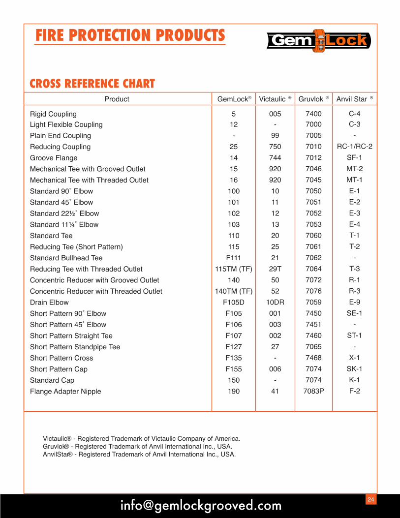
FIRE PROTECTION PRODUCTS
CROSS REFERENCE CHARTProduct GemLock Victaulic ®® Gruvlok ® Anvil Star ®
Rigid CouplingLight Flexible CouplingPlain End CouplingReducing CouplingGroove FlangeMechanical Tee with Grooved OutletMechanical Tee with Threaded OutletStandard 90˚ ElbowStandard 45˚ ElbowStandard 22½˚ ElbowStandard 11¼˚ ElbowStandard TeeReducing Tee (Short Pattern)Standard Bullhead TeeReducing Tee with Threaded OutletConcentric Reducer with Grooved OutletConcentric Reducer with Threaded OutletDrain ElbowShort Pattern 90˚ ElbowShort Pattern 45˚ ElbowShort Pattern Straight TeeShort Pattern Standpipe TeeShort Pattern CrossShort Pattern CapStandard CapFlange Adapter Nipple
512-
25141516
100101102103110115F111
115TM (TF)140
140TM (TF)F105DF105F106F107F127F135F155150190
005-
9975074492092010111213202521
29T5052
10DR00100300227-
006-
41
7400700070057010701270467045705070517052705370607061706270647072707670597450745174607065746870747074
7083P
C-4C-3
-RC-1/RC-2
SF-1MT-2MT-1E-1E-2E-3E-4T-1T-2
-T-3R-1R-3E-9
SE-1-
ST-1-
X-1SK-1K-1F-2
Victaulic® - Registered Trademark of Victaulic Company of America.Gruvlok® - Registered Trademark of Anvil International Inc., USA.AnvilStar® - Registered Trademark of Anvil International Inc., USA.

Terms: Net 30 DaysAccounts over 30 days will be charged 1-1/2% interest per month (18% per annum).
Completion of all orders accepted and fulfillment of all agreements or contracts entered into are subject to any delay which mightbe occasioned by strikes, fires, accidents or other causes whether or not beyond our control and Gemlock®, all Subsidiaries and/or Affiliates shall not be liable for any consequential damages arising from any such delay.
We guarantee products which are manufactured by Gemlock, or its Subsidiaries and/or Affiliates, and will replace those having manufac-turing defects, when used in the service of which we recommend them.
No charge for labor or expense required to repair defective goods will be accepted. The measure of the damage is the replacement of the defective goods or the cost of said goods only.
All allegedly defective goods must be returned as a condition of replacement or credit.
No goods will be taken back and credited unless our consent has been first obtained, and accompanied by a return authorization memo.
All products returned with our permission must be goods obtained through us and in clean salable condition.
All products returned will be covered by the manufacturerʼs warranty only.
Credit will only be allowed on the basis of prices agreed upon, less 20% to cover handling costs, less any costs of putting in salable condition, and less transportation charges on original and return shipments.
Orders for fabricated goods are not subject to cancellation for any reason whatsoever after work has been started on them, except upon agreement to make payment for all work which has been performed.
All promises of shipment will be as closely estimated as possible. We use our efforts in every case to ship within the time promised, but cannot guarantee to do so.
All claims for shortage must be made on receipt of goods.
Clerical errors are subject to corrections.
Upon opening and/or maintaining an account with Gemlock, or any of its Subsidiaries and/or Affiliates, youhereby agree that all disputes, including those arising as a result of your nonpayment may be submitted to New York State courtslocated in Nassau County (including Nassau County district courts).
Any claims against GemLock®, and or any of its Subsidiaries and/or Affiliates must be brought, if at all, in theSupreme or District court of the State of New York, County of Nassau.
In the event your account is placed with an attorney for collections, you will be responsible for attorneyʼs fees in the amount notless than 25% of your outstanding balance.
These terms may be modified from time to time. In such event you will be bound by such revised terms unless you elect inwriting, within five (5) business days of receipt of said revised terms to close your account and your account is paid in full withinsixty (60) days thereafter.
2560 Cohoes Ave. Green Island, NY 12183 • Ph: (518) 270-2159 • Fax: (518) 270-8384

NOTES:
___________________________________________________________________
___________________________________________________________________
___________________________________________________________________
___________________________________________________________________
___________________________________________________________________
___________________________________________________________________
___________________________________________________________________
___________________________________________________________________
___________________________________________________________________
___________________________________________________________________
___________________________________________________________________
___________________________________________________________________
___________________________________________________________________
___________________________________________________________________
___________________________________________________________________
___________________________________________________________________
___________________________________________________________________

GemLock Grooved Products60 Cohoes Ave. Green Island, NY 12183 • Ph: (518) 270-2159 • Fax: (518) 270-8384
www.gemlockgrooved.com
®


