Fingering instability of a retracting solid film edge Wanxi Kan and Harris Wong Citation: Journal of Applied Physics 97, 043515 (2005); doi: 10.1063/1.1845579 View online: http://dx.doi.org/10.1063/1.1845579 View Table of Contents: http://scitation.aip.org/content/aip/journal/jap/97/4?ver=pdfcov Published by the AIP Publishing Advertisement: [This article is copyrighted as indicated in the abstract. Reuse of AIP content is subject to the terms at: http://scitation.aip.org/termsconditions. Downloaded to ] IP: 192.133.28.4 On: Thu, 24 Oct 2013 13:09:33
Transcript
Fingering instability of a retracting solid film edgeWanxi Kan and Harris Wong Citation: Journal of Applied Physics 97, 043515 (2005); doi: 10.1063/1.1845579 View online: http://dx.doi.org/10.1063/1.1845579 View Table of Contents: http://scitation.aip.org/content/aip/journal/jap/97/4?ver=pdfcov Published by the AIP Publishing Advertisement:
[This article is copyrighted as indicated in the abstract. Reuse of AIP content is subject to the terms at: http://scitation.aip.org/termsconditions. Downloaded to ] IP:
Thin solid films are the basic components in many mi-croelectronic and optoelectronic devices.1,2 Nowadays, thesedevices are made smaller by reducing the size of thin films.As films become smaller, the surface-to-volume ratio ishigher and the capillary force stronger. Since the same filmsurface displacement has more effect on the structural integ-rity of a smaller film, morphological evolution and stabilityof thin films are becoming more important.
In an experiment to study the effect of annealing on thinfilms, Kennefick and Raj deposited uniform copper films onsapphire.3 The thickness of these uniform films ranged from50 to 250 nm. The film and the substrate were annealed at650 °C under nonoxidizing conditions for 20 min to 48 h.They found that holes form at foreign, nonwetting inclu-sions, and the film starts to breakup at the boundaries of theholes. This breakup proceeds until the entire film decom-poses into isolated, irregular islands. To study this breakupprocess quantitatively, Jiran and Thompson deposited uni-form gold-film strips on silica substrates and studied the re-traction of the film edges.4,5 These strips were 25mm wideand at least 250mm long with a uniform thickness rangingfrom 40 to 90 nm. When the strips were annealed at700–800 °C for about an hour, the initially smooth andstraight edges become unstable and develop large amplitudeundulations, which eventually extend into “fingers.” Thesefingers then pinch off to form isolated islands to reduce thetotal surface energy of the system. This finger-forming andpinch-off process continues until the entire film strip disinte-grates. In electronic materials processing, it is important that
a bounded uniform film remains continuous. Therefore, thisfingering instability needs to be understood and suppressed.
The pioneer work of Kennefick and Raj showed that filmdisintegration starts from holes.3 This seems to suggest thatthe stability of holes may play a role. The stability of anarray of cylindrical holes in a uniform film has been ana-lyzed by Srolovitz and Safran.6 They compared the total sur-face energy of a unit cell of the array with that of a film withno hole but with the same film volume. They found that ahole may close completely or open toward a stable size. In acompanion paper, they numerically simulated the axisym-metric evolution of a hole in a uniform film.7 The hole is notin equilibrium initially, and it evolves by either surface dif-fusion or evaporation–condensation. In either case, there ex-ists a critical hole size, above which the hole grows, andbelow which it shrinks. Their stability analyses are axisym-metric and, therefore, cannot describe the fingering instabil-ity at the hole edge. Recently, Wonget al. investigated thelinear stability of a catenoidal hole in a solid film.8 Unlikethe hole shapes studied by Srolovitz and Safran, a catenoid isin equilibrium because the circumferential curvature bal-ances the radial curvature at every point on the surface. It isthe only equilibrium shape that can be patched to a uniformfilm far from the hole. The catenoidal hole is perturbed inboth radial and circumferential directions, assuming that theperturbation evolves by surface diffusion. The perturbation isthen expanded in normal modes with their growth rates de-termined by solving an eigenvalue problem. The resultsshow that a catenoidal hole is always unstable to an axisym-metric perturbation, but is stable to perturbations in the cir-cumferential direction. Thus, the hole may open or close, butit will remain circular. Therefore, the instability of thecatenoidal hole cannot lead to the fingering instability at thehole edge.
adAuthor to whom correspondence should be addressed; electronic mail:[email protected]
[This article is copyrighted as indicated in the abstract. Reuse of AIP content is subject to the terms at: http://scitation.aip.org/termsconditions. Downloaded to ] IP:
The experiments of Jiran and Thompson revealed that astraight film edge can be unstable.4,5 This suggests that thecircular hole geometry is not needed for the fingering insta-bility to occur, and we should focus on film edges that arestraight. The retraction of a straight edge of a uniform filmhas been studied by Wonget al.9 They assumed that theuniform film is two dimensional and evolves by surface dif-fusion. One end of the uniform film retracts while the otherend is undisturbed and goes to infinity, because the width-to-thickness ratio is about 500 for the film strips in Jiran andThompson’s experiments. They found that the retracting endis thickened at the edge into a ridge followed by a valley, asshown in Fig. 1. The valley sinks with time and eventuallytouches the substrate. The ridge then detaches from the film.The new film edge retracts to form another ridge accompa-nied again by a valley, and the mass shedding cycle is re-peated. Since their analysis is two dimensional, it cannotdescribe the fingering instability, but it does give a breakupmechanism in two dimensions, and the predicted retractionspeed agrees quantitatively with that observed in Jiran andThompson’s experiments.9
The present work analyzes the stability of the retractingfilm profile obtained by Wonget al.9 Their two-dimensionalfilm profile is perturbed in three dimensions. The growth rateof the perturbation is determined as a function of the wave-length of the perturbation and the speed of the receding edge.We find one unstable mode of perturbation, which makes theoriginally straight film edge wavy. Further growth of thisunstable mode can lead to the fingers observed by Jiran andThompson.4,5
This fingering instability also appears in high-temperature crack healing. Cracks formed in ceramics reducethe strength of the materials significantly. At high tempera-tures, however, cracks heal by diffusional processes, allow-ing partial to complete recovery of the materials’strength.10,11 Recently, an idealized system for studyingcrack healing has been developed in which rectangular cavi-ties are created in sapphire by a combination of photolithog-raphy patterning, ion-beam etching, and hot-pressbonding.12–14 The rectangular cracks are of size 1003200 mm2 and thickness 0.13, 0.17, or 0.30mm.14 Thecracks are annealed at 1700 °C for up to 21 h. This providesa well-defined system in which crack healing can be studiedas functions of crack geometry, crack-face crystallographyand microstructure, and impurities. It is found that underannealing the perimeter of the rectangular crack either con-tracts uniformly with the edges maintaining straight or de-velops undulations that eventually breakup the rectangular
crack into isolated bubbles. The onset of the edge instabilityseems to depend on crack-face crystallography and the typeof ions implanted. For faster healing of cracks, it is desirableto promote this edge instability.
Although morphological evolution of thin films seems tobe very different from that of rectangular cracks, both areactually governed by the same equation. This is because thethicknesses of the films and the cracks are less than 10mmand because both are annealed at temperatures much lowerthan their melting temperatures. Under these conditions, sur-face diffusion is the dominant mechanism of masstransport.15,16 Because mass moves along the surface, thegoverning equation is the same, independent of which side ofthe surface the solid lies. Thus, the governing equation ap-plies equally well to a solid film and to a cavity. However,there exists a major difference. For thin-film annealing, thefingering instability needs to be suppressed, whereas, forcrack healing, the edge instability is desirable because it ex-pedites the healing. Thus, it is important to understand thisedge instability so that it can be controlled.
This paper is organized as follows. The base state andthe perturbation are described in Sec. II. The resulting eigen-value problem has an analytic solution that requires numeri-cal evaluationsSec. IIId. Numerical results are presented inSec. IV. Asymptotic solutions are derived in Sec. V and com-pared with the numerical results. We discuss the implicationsin Sec. VI and conclude in Sec. VII.
II. MATHEMATICAL MODEL
A. Base state
The retraction of a two-dimensional step film on a sub-strate has been studied recently by Wonget al.9 The filmprofile at zero time is a step, and it rearranges very quickly atthe contact line to form an equilibrium anglea with thesubstrate. The film then retracts with a thickened edge fol-lowed by a valley, as illustrated in Fig. 1. When a solid filmevolves by capillarity-driven surface diffusion, the film sur-face displaces with a normal velocityun that obeys17
un = B¹s2k, s1d
in which ¹s is the surface gradient operator,k is the surfacemean curvature, andB is a material constantsB=DsgyV2/kBTe, whereDs is the surface diffusivity,g is thesurface energy per unit area which is taken as isotropic,y isthe number of diffusing atoms per unit area,V is the atomicvolume, andkBTe is the thermal energyd. This equation isderived using the fact that the chemical potential varies lin-early with the curvature of the solid film surface. If the sur-face curvature is not uniform, then a gradient in chemicalpotential exists. This gradient drives a surface flux, whichredistributes mass along the solid surface. The net effect isthat the solid surface moves in the normal direction. Equa-tion s1d has been applied to model grain-boundary groovingfor measuring surface diffusivities18–22 and to model otherphysical phenomena.16,23,24
For the retraction of a uniform film, such as that shownin Fig. 1, the unperturbed film thicknessH constitutes a natu-
FIG. 1. A sketch of a solid film edge. The two-dimensional base-state filmprofile intercepts the substrate atx=x0 with contact anglea ssolid lined. Thiscontact angle is maintained for the perturbed profilesdashed lined. The far-field film heightH constitutes a natural length scale.
043515-2 W. Kan and H. Wong J. Appl. Phys. 97, 043515 ~2005!
[This article is copyrighted as indicated in the abstract. Reuse of AIP content is subject to the terms at: http://scitation.aip.org/termsconditions. Downloaded to ] IP:
192.133.28.4 On: Thu, 24 Oct 2013 13:09:33
ral length scale. In what follows, length and time are madedimensionless byH andH4/B, respectively. In dimensionlessvariables,s1d becomes
un = ¹s2k. s2d
This governing equation is subjected to the following bound-ary conditions. At the contact line, the height of the film iszero, the contact angle is in equilibrium, and the mass flux iszero. Far from the contact line, the film is not disturbed andhas unit height.
When the contact anglea.30°, Wonget al. solved theevolving film profile for differenta by a numerical method.9
However, when the contact anglea→0, the breakup timetends to infinity, and the numerical simulation takes too longto reach film breakup. Thus, a small-slope analytic solutionis found that is valid for timet@1. This small-slope solutionis derived by first defining a coordinatex* that moves withthe contact line:
x * ; x − x0std, s3d
wherex0std is the position of the contact line. A new set ofvariables
X = ax * , Y = y, T = a4t, s4d
transforms the governing Eq.s2d into
]Y
]T− b3]Y
]X= −
]4Y
]X4 , s5ad
b =1
aSdx0
dtD1/3
, s5bd
where the small-slope assumption has been invoked, and themotion is confined to two dimensions. By assuming that thetime derivative term is small compared with the other twoterms, Wonget al.9 found a series solution for the retractingfilm profile Ys. The first two terms are
YssT;Xd = Y0 + Y1, s6ad
Y0 = 1 +e−bX/2FS2 − bÎ3b
DsinSÎ3
2bXD − cosSÎ3
2bXDG ,
s6bd
Y1 = S1 +5b
6D b
12e−bX/2HXsX + 4dcosSÎ3
2bXD
− fbs1 − 2bdX2 + 4s3 − bdX + 8g1
Î3bsinSÎ3
2bXDJ ,
s6cd
b = S 2
5TD1/5
−5
24S 2
5TD2/5
+ , . . . , s6dd
wheredb/dT in the original expression ofY1 has been evalu-ated usings6dd and expressed in terms ofb. Solution s6dsatisfiess5d with a residual]Y1/]T, which vanishes asT→`. The film profile represented bys6d is steady in thesense that it is independent of time explicitly, but it depends
on time implicitly through its dependence onb. This timedependence is weak, so that the film profileYs evolvesslowly.
B. Normal-mode analysis
In three dimensions, the governing Eq.s2d under thesmall-slope assumption and in a frame moving with the con-tact line becomes
]Y
]T− b3]Y
]X= − S ]4Y
]X4 + 2]4Y
]X2]Z2 +]4Y
]Z4D , s7ad
Z = az, s7bd
wherez is the coordinate perpendicular tox andy. The base-state profile ins6d is perturbed as
YsT,X,Zd = YssT;Xd + dsT,X,Zd. s8d
Substitutings8d into s7d and assuming]Y1/]T!]d /]T yields
]d
]T− b3 ]d
]X= − S ]4d
]X4 + 2]4d
]X2dZ2 +]4d
]Z4D . s9d
The disturbance is then expressed in normal modes
dsT,X,Zd = esT cosskZdfsXd, s10d
wheres is the growth rate or the eigenvalue andfsXd is theeigenfunction. Substitution ofs10d into s9d leads to an eigen-value problem:
d4f
dX4 − 2k2 d2f
dX2 − b3 df
dX+ k4f + sf = 0. s11d
Solution of this equation yields the growth ratea in terms ofthe wave numberk and constantb. fThe parameterb dependson time, but can be treated as constant ins11dg.
C. Boundary conditions for the eigenvalue problem
Boundary conditions forfsXd are complicated becausethe boundary location is unknown. At the contact line,X=Xp svalue unknownd,
Y = 0, s12ad
n ·eY = cosa, s12bd
m ·¹sk = 0, s12cd
where
n =− YXeX + eY − YZeZ
Î1 + YX2 + YZ
2, s12dd
m =YXeX + sYX
2 + YZ2deY + YZeZ
ÎYX2 + YZ
2 + sYX2 + YZ
2d2, s12ed
043515-3 W. Kan and H. Wong J. Appl. Phys. 97, 043515 ~2005!
[This article is copyrighted as indicated in the abstract. Reuse of AIP content is subject to the terms at: http://scitation.aip.org/termsconditions. Downloaded to ] IP:
192.133.28.4 On: Thu, 24 Oct 2013 13:09:33
¹s =1
1 + YX2 + YZ
2HeXFs1 + YZ2d
]
]X− YXYZ
]
]ZG
+ eYSYX]
]X+ YZ
]
]ZD + eZFs1 + YX
2d]
]Z
− YXYZ]
]XGJ , s12fd
k = ¹s ·n. s12gd
In the above equations,eX, eY, andeZ represent until vectorsin the X, Y, and Z directions,n is the unit surface normalsFig. 1d, m is a unit vector tangent to the film surface andnormal to the contact line, and the subscriptsX andZ of Ydenote differentiation. The boundary conditions ins12d statethat the height of the film is zero, the contact angle is fixed,and the mass flux tangent to the film surface and into thesubstrate is zero at the contact line. The contact line atX=Xp is the interception point of the perturbed film profilewith the substratesFig. 1d. This contact-line position canvary and is unknown, and must be solved together with thefilm profile. Fortunately, for this linear perturbation problem,the boundary conditions can be Taylor expanded about thepositionX=0 of the base-state contact line to leading orderin d. The positionX=0 is the interception point of the base-state film profile with the substrate orx=x0 in Fig. 1.
Substitution ofY=Ys+d into s12d, keeping only linearterms ind, and expanding the results aroundX=0 gives thatat X=0 sAppendix Id,
6df
dX+ bs6 − bdf = 0, s13ad
d3f
dX3 − k2 df
dX− b3f = 0. s13bd
As X→`,
f → 0, s14ad
df
dX→ 0. s14bd
Note that the three boundary conditions at the contact line ins12d are combined into two ins13d, and that all the boundaryconditions are homogeneous.
III. SOLUTION OF THE EIGENVALUE PROBLEM
Sinces11d is linear in f with constant coefficients, a gen-eral solution is
fsXd = oj=1
4
CjeajX. s15d
The constantsaj, j =1, . . . ,4, are found by substitutings15dinto s11d and solving the quartic algebraic equation usingMaple V®:25
a1 = p + q, s16ad
a2 = p − q, s16bd
a3 = − p + r , s16cd
a4 = − p − r , s16dd
p =1
2Î6Î8k2 + s1/3 + s48s + 64k4ds−1/3, s16ed
q =1
2Î6Îu + 6b3p−1, s16fd
r =1
2Î6Îu − 6b3p−1, s16gd
u = 16k2 − s1/3 − 48ss−1/3 − 64k4s−1/3, s16hd
s= 576k2s + 512k6 + 108b6
+ 12Î768sb6k6 − s2k4 − s3d + 9b6s96sk2 + 9b6d.
s16id
To find the eigenvalues, we impose the homogeneousboundary conditionss13d and s14d and seek a nontrivial so-lution for Cj, j =1, . . . ,4. Since the boundary location atwhich s14d is applied is at infinity, a positive real part ofaj
forcesCj =0. The real part ofaj or Rsajd is plotted on thecomplex plane ofs for a full range ofk and b. It is foundthat Rsa1d.0 and Rsa2d.0 for Rssd.0. fNo conclusioncan be drawn forRsajd in the domainRssdø0.g Thus, C1
=C2=0 for a bounded solution, and we are left with
AC = 0, s17ad
whereA is a second-order matrix with elements
A11 = b2 − 6b − 6a3, s17bd
A12 = b2 − 6b − 6a4, s17cd
A21 = b3 + k2a3 − a33, s17dd
A22 = b3 + k2a4 − a43, s17ed
and
C = SC3
C4D . s17fd
Thus, the four unknown coefficientsCj are reduced to two.To have a nontrivial solution forC, we need
uA u = 0. s18ad
If we denote the real and imaginary parts ofuA u by Ar andAi,respectively, then
Ar = 0, Ai = 0. s18bd
Solution of these two equations yieldssr andsi, the real andimaginary parts ofs. Since these equations are difficult tosolve, we plotAr and Ai on the complex plane ofs for agiven set ofk andb values. We find thatAr =0 is a segmentalong the linesi =0 andAi =0 is an arc that intercepts thisline segment at only one point. Thus, the interception point,
043515-4 W. Kan and H. Wong J. Appl. Phys. 97, 043515 ~2005!
[This article is copyrighted as indicated in the abstract. Reuse of AIP content is subject to the terms at: http://scitation.aip.org/termsconditions. Downloaded to ] IP:
192.133.28.4 On: Thu, 24 Oct 2013 13:09:33
which is an eigenvalue ofs11d, is always real. The positionof that point is found by bisection to an accuracy of eightsignificant digits.
IV. NUMERICAL RESULTS
The growth rates is plotted as a function of the wavenumberk for b=0.1 in Fig. 2. The growth rate increases withk starting atk=0 until s reaches a maximum value ofsm atk=km. The growth rate then decreases monotonically, passingthrough zero at a critical wave numberkc. Thus, whenk,kc, the film is unstable whereas the perturbation is stablewhenkùkc.
Perturbations usually come from random noise thatspans the whole spectrum of wavelength. The perturbationwith wavelengthk=km and maximum growth rates=sm ismost likely to be observed at late times. Thus, these resultsdeserve more attention. Figure 3 shows the eigenfunctionfsXd when b=0.1 andk=km=0.0685. The eigenfunction iscomputed froms15d and is the sum of two complex expo-
nential functions ofX, both decaying inX. The eigenfunctionhas the highest magnitude atX=0, and it oscillates aroundzero with exponentially decaying peak amplitudes. Theeigenfunction reflects the shape of the perturbation in theXdirection at constantZ, as defined ins10d. The effect of theperturbationd on the base state is revealed by superimposingthe perturbation on the base-state profile, as shown in Fig. 4.The magnitude of the perturbation is 20% of the peak filmheight. Figure 4sad projects the film profile in three dimen-sions, whereas Fig. 4sbd contrasts the cross sections atZ=0and p /k, which correspond to the positive and negativemaximum amplitudes of the perturbation. The figures showthat the perturbation affects the ridge region the most; thepeak of the ridge atX<10 is wavy. The effect of the pertur-bation can barely be seen at the valley of the film atX<40.
At k=kc, s=0 and the perturbationd satisfies the steadyform of s9d. Thus, the perturbed film profileY in s8d can betaken as a new three-dimensional base state. The eigenfunc-tion for k=kc andb=0.1 is also plotted in Fig. 3; it is the sum
FIG. 2. Growth rates vs wave numberk for b=0.1. The maximum growthrate s=sm=5.997310−5 occurs at k=km=0.0685, ands=0 at k=kc
=0.1084.
FIG. 3. Eigenfunctions computed usings15d for b=0.1.
FIG. 4. The perturbed film shape forb=0.1 and wave numberk=km
=0.0685. The magnitude of the perturbation is 20% of the peak film height.sad Three-dimensional projection showing the wavy peak of the ridge atX<10. TheX position of the contact line varies sinusoidally withZ followings10d and sA3d. sbd Cross sections atZ=0 andp /k. These positions corre-spond to the positive and negative maximum amplitudes of the perturbation.
043515-5 W. Kan and H. Wong J. Appl. Phys. 97, 043515 ~2005!
[This article is copyrighted as indicated in the abstract. Reuse of AIP content is subject to the terms at: http://scitation.aip.org/termsconditions. Downloaded to ] IP:
192.133.28.4 On: Thu, 24 Oct 2013 13:09:33
of two complex exponential functions ofX, just like theeigenfunction fork=km. However, the oscillation is hardlyobservable. The perturbed film profile is similar to the oneshown in Fig. 4, especially near the ridge region.
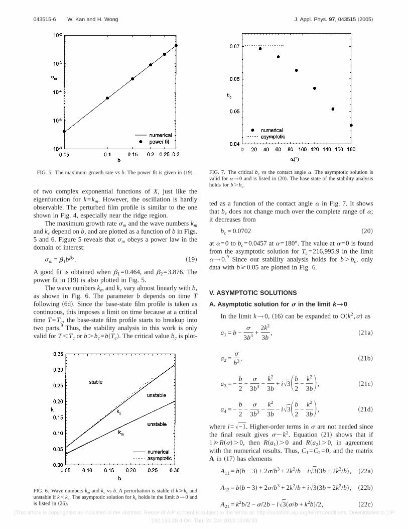
The maximum growth ratesm and the wave numberskm
andkc depend onb, and are plotted as a function ofb in Figs.5 and 6. Figure 5 reveals thatsm obeys a power law in thedomain of interest:
sm = b1bb2. s19d
A good fit is obtained whenb1=0.464, andb2=3.876. Thepower fit in s19d is also plotted in Fig. 5.
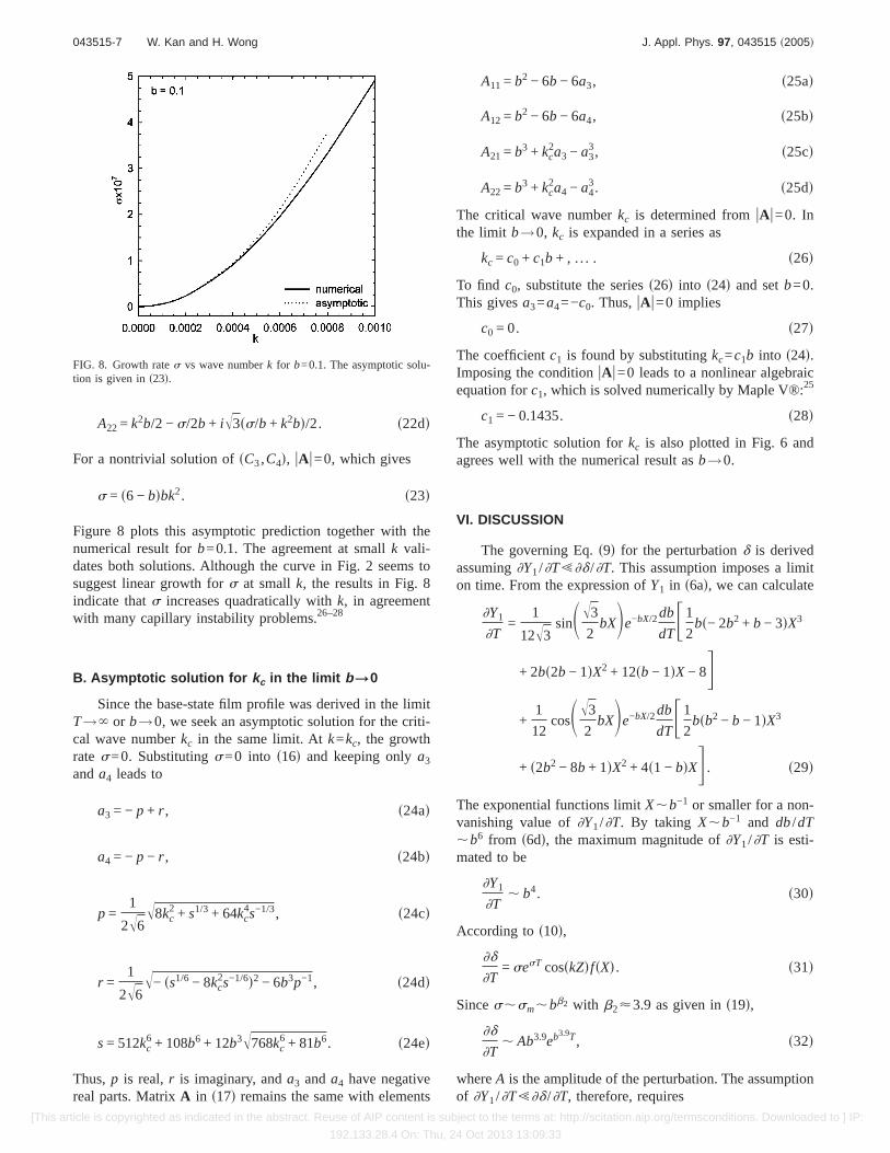
The wave numberskm andkc vary almost linearly withb,as shown in Fig. 6. The parameterb depends on timeTfollowing s6dd. Since the base-state film profile is taken ascontinuous, this imposes a limit on time because at a criticaltime T=Tc, the base-state film profile starts to breakup intotwo parts.9 Thus, the stability analysis in this work is onlyvalid for T,Tc or b.bc=bsTcd. The critical valuebc is plot-
ted as a function of the contact anglea in Fig. 7. It showsthat bc does not change much over the complete range ofa;it decreases from
bc = 0.0702 s20d
at a=0 to bc=0.0457 ata=180°. The value ata=0 is foundfrom the asymptotic solution forTc=216,995.9 in the limita→0.9 Since our stability analysis holds forb.bc, onlydata withbù0.05 are plotted in Fig. 6.
V. ASYMPTOTIC SOLUTIONS
A. Asymptotic solution for s in the limit k\0
In the limit k→0, s16d can be expanded to Osk2,sd as
a1 = b −s
3b3 +2k2
3b, s21ad
a2 =s
b3 , s21bd
a3 = −b
2−
s
3b3 −k2
3b+ iÎ3Sb
2−
k2
3bD , s21cd
a4 = −b
2−
s
3b3 −k2
3b− iÎ3Sb
2−
k2
3bD , s21dd
wherei =Î−1. Higher-order terms ins are not needed sincethe final result givess,k2. Equation s21d shows that [email protected], then Rsa1d.0 and Rsa2d.0, in agreementwith the numerical results. Thus,C1=C2=0, and the matrixA in s17d has elements
FIG. 5. The maximum growth rate vsb. The power fit is given ins19d.
FIG. 6. Wave numberskm andkc vs b. A perturbation is stable ifkùkc andunstable ifk,kc. The asymptotic solution forkc holds in the limitb→0 andis listed in s26d.
FIG. 7. The criticalbc vs the contact anglea. The asymptotic solution isvalid for a→0 and is listed ins20d. The base state of the stability analysisholds forb.bc.
043515-6 W. Kan and H. Wong J. Appl. Phys. 97, 043515 ~2005!
[This article is copyrighted as indicated in the abstract. Reuse of AIP content is subject to the terms at: http://scitation.aip.org/termsconditions. Downloaded to ] IP:
192.133.28.4 On: Thu, 24 Oct 2013 13:09:33
A22 = k2b/2 − s/2b + iÎ3ss/b + k2bd/2. s22dd
For a nontrivial solution ofsC3,C4d, uA u=0, which gives
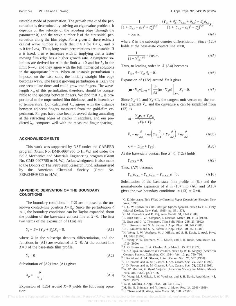
s = s6 − bdbk2. s23d
Figure 8 plots this asymptotic prediction together with thenumerical result forb=0.1. The agreement at smallk vali-dates both solutions. Although the curve in Fig. 2 seems tosuggest linear growth fors at smallk, the results in Fig. 8indicate thats increases quadratically withk, in agreementwith many capillary instability problems.26–28
B. Asymptotic solution for kc in the limit b\0
Since the base-state film profile was derived in the limitT→` or b→0, we seek an asymptotic solution for the criti-cal wave numberkc in the same limit. Atk=kc, the growthrate s=0. Substitutings=0 into s16d and keeping onlya3
anda4 leads to
a3 = − p + r , s24ad
a4 = − p − r , s24bd
p =1
2Î6Î8kc
2 + s1/3 + 64kc4s−1/3, s24cd
r =1
2Î6Î− ss1/6 − 8kc
2s−1/6d2 − 6b3p−1, s24dd
s= 512kc6 + 108b6 + 12b3Î768kc
6 + 81b6. s24ed
Thus,p is real,r is imaginary, anda3 anda4 have negativereal parts. MatrixA in s17d remains the same with elements
A11 = b2 − 6b − 6a3, s25ad
A12 = b2 − 6b − 6a4, s25bd
A21 = b3 + kc2a3 − a3
3, s25cd
A22 = b3 + kc2a4 − a4
3. s25dd
The critical wave numberkc is determined fromuA u=0. Inthe limit b→0, kc is expanded in a series as
kc = c0 + c1b + , . . . . s26d
To find c0, substitute the seriess26d into s24d and setb=0.This givesa3=a4=−c0. Thus,uA u=0 implies
c0 = 0. s27d
The coefficientc1 is found by substitutingkc=c1b into s24d.Imposing the conditionuA u=0 leads to a nonlinear algebraicequation forc1, which is solved numerically by Maple V®:25
c1 = − 0.1435. s28d
The asymptotic solution forkc is also plotted in Fig. 6 andagrees well with the numerical result asb→0.
VI. DISCUSSION
The governing Eq.s9d for the perturbationd is derivedassuming]Y1/]T!]d /]T. This assumption imposes a limiton time. From the expression ofY1 in s6ad, we can calculate
]Y1
]T=
1
12Î3sinSÎ3
2bXDe−bX/2db
dTF1
2bs− 2b2 + b − 3dX3
+ 2bs2b − 1dX2 + 12sb − 1dX − 8G+
1
12cosSÎ3
2bXDe−bX/2db
dTF1
2bsb2 − b − 1dX3
+ s2b2 − 8b + 1dX2 + 4s1 − bdXG . s29d
The exponential functions limitX,b−1 or smaller for a non-vanishing value of]Y1/]T. By taking X,b−1 and db/dT,b6 from s6dd, the maximum magnitude of]Y1/]T is esti-mated to be
]Y1
]T, b4. s30d
According tos10d,
]d
]T= sesT cosskZdfsXd. s31d
Sinces,sm,bb2 with b2<3.9 as given ins19d,
]d
]T, Ab3.9eb3.9T, s32d
whereA is the amplitude of the perturbation. The assumptionof ]Y1/]T!]d /]T, therefore, requires
FIG. 8. Growth rates vs wave numberk for b=0.1. The asymptotic solu-tion is given ins23d.
043515-7 W. Kan and H. Wong J. Appl. Phys. 97, 043515 ~2005!
[This article is copyrighted as indicated in the abstract. Reuse of AIP content is subject to the terms at: http://scitation.aip.org/termsconditions. Downloaded to ] IP:
192.133.28.4 On: Thu, 24 Oct 2013 13:09:33
b4 ! Ab3.9eb3.9T. s33d
Substitution ofs6dd into s33d yields
T @ s− ln Ad4.5. s34d
Given a perturbation of amplitudeA, our stability analysisholds for timeT satisfying the above condition.
Jiran and Thompson observed that a gold-film strip un-der annealing develops fingers at the retracting film edges.5
From Fig. 1 of their paper, we measured the distance be-tween adjacent fingers and got 1.5–3mm. Our stabilityanalysis predicts that a retracting film edge is unstable. Theunstable mode makes the film edge wavy, which is the pre-cursor of the fingers seen in Jiran and Thompson’s experi-ment. The perturbation with the highest growth rate is likelythe one survived at late times. The wavelength of this mostunstable perturbation should determine the distance betweenadjacent fingers. This wavelength in dimensional units is
lm =2pH
kma. s35d
The thicknessH=0.05mm for the gold film in Fig. 1 of Jiranand Thompson’s paper.5 For gold films on silica the contactanglea<p.4 However,s35d is valid for smalla. Thus, weassumea=p /2 as a compromise. From Fig. 6,km variesslowly over the range ofb that is of interest. As an example,we take b=0.1. This gives km=0.0685, and thuslm
=2.9 mm, in agreement with the distance between fingersobserved in Jiran and Thompson’s experiment. Note that thematerial constantB that contains the surface diffusivity doesnot appear explicitly ins35d. The material constant does af-fect km=kmsbd becauseb=bsTd andT is made dimensionlessby use ofB. However, sincekm is a slow varying function ofb, lm is insensitive toB and is, therefore, insensitive to tem-perature.
The most unstable perturbation may breakup the film ina time t given by tsm,1. This estimate comes from theexponential growth of the perturbation. In dimensionalterms, this breakup time is
t * =H4
Ba4sm. s36d
Thus, thicker films or films with smaller contact angles takelonger time to breakup and, therefore, are more stable. Thequartic dependence onH /a indicates thatt* is highly sensi-tive to values ofH anda. To calculate a typical value fort*,we consider the gold film in Jiran and Thompson’sexperiment,5 in which H=0.05mm, and we again usea=p /2. For Au at 775 °C, Ds=2.02310−6 cm2/s,29 g=1.78 J/cm2,30 V=1.78310−23 cm3, and we takey<V−2/3
=1.531015 cm−2. Thus, B=1.2310−4 mm4/s. The maxi-mum growth ratesm,b3.8, as shown in Fig. 5. If for conve-nience we assumeb=0.1, thensm=5.997310−5, and thust* =140 s.
The value oflm is reliable sincekm is insensitive tovariation inb. However, the value oft* can only be viewedas typical becausesm increases by about 1000 times over therange ofb. There is no good guideline to pinpoint a value forb. The base state of the stability analysis holds in the limit
T→` or b→0. The assumption]d /]T@]Y1/]T of the per-turbation equation leads toT@ s−ln Ad4.5 in s34d or b! sln Ad−0.9. This together withb.bc in s20d brackets arange ofb that the stability analysis applies. However, thesensitivity ofsm to variation inb makes it difficult to arriveat an accurate estimate oft*. Probably, the only conclusionthat can be inferred fromsmsbd is that the fingering instabil-ity would breakup the film at an early stage of retraction.
The fingering instability also applies to crack healing, asexplained in the introduction. Rectangular cracks in Ti-implanted sapphire develop fingers along the retracting edgeswhen the samples are annealed for 5 min at 1700 °C.14 Therectangular cracks are of size 1003200 mm2 and thickness0.13 or 0.30mm. The fingers are observed along the two
long edges that are oriented parallel to thef1100g direction.The distance between adjacent fingers ranges from3 to 6 mm as measured from Fig. 4 in Powers and Glaeser14
and the average is 4.6mm. We compare this distance withthe wavelengthlm of the fastest growing mode given ins35d.We again takeb=0.1 or km=0.0685. If the contact anglea=90°, then the substrate can be viewed as a symmetry plane,so that the base-state film profile describes half of a retract-ing cavity.9 Hence, the film thicknessH is half of the crackthickness. However, the thickness is not given for the rect-angular crack in Fig. 4 in Powers and Glaeser.14 The onlyinformation provided in their paper is that the idealizedcracks in Ti-implanted sapphire have a thickness of 0.13 or0.30mm. sDr. Glaeser through a private communicationguessed that the rectangular crack shown in their Fig. 4 be-longs to the shallower type, but he could not be sure.d Thus,we consider both possibilities and takeH=0.065 or0.15mm. This leads tolm=3.8 or 8.8mm. The agreement isencouraging considering the uncertainty in selecting a valuefor km and the assumption of smalla in deriving s35d.
The fingers at the crack edges eventually pinch off toleave behind rows of bubbles.14 The crack fronts thensmoothen and straighten after further annealing, and thecracks in Ti-implanted sapphire do not breakup even afteranother 21 h of annealing. The cracks in undoped or Ca- orMg-doped sapphire do breakup into isolated bubbles, but thebubble size and spacing are much larger than what should beexpected from the fingering instability.14 It seems that theRayleigh instability of the channel at the crack perimeter isresponsible for the final breakup of the cracks.9
VII. CONCLUSIONS
The gold-film strips under annealing on the silica sub-strates have been observed to retract and develop large am-plitude undulations at the film edges. These fingers elongateas the edges recede, and, finally, detach from the film to formisolated islands. This work studies the instability of a retract-ing film edge on a substrate. The base state of the stabilityanalysis is a two-dimensional uniform film that is retractingat one end and unbounded at the other end. The retractingend is thickened at the edge followed by a valley before thefilm thickness becomes uniform. This two-dimensional pro-file is perturbed in three dimensions, assuming that the filmevolves by capillarity-driven surface diffusion. We find one
043515-8 W. Kan and H. Wong J. Appl. Phys. 97, 043515 ~2005!
[This article is copyrighted as indicated in the abstract. Reuse of AIP content is subject to the terms at: http://scitation.aip.org/termsconditions. Downloaded to ] IP:
192.133.28.4 On: Thu, 24 Oct 2013 13:09:33
unstable mode of perturbation. The growth rates of the per-turbation is determined by solving an eigenvalue problem. Itdepends on the velocity of the receding edgesthrough theparameterbd and the wave numberk of the sinusoidal per-turbation along the film edge. For a givenb, there exists acritical wave numberkc such thats.0 for k,kc, and sø0 for kùkc. Thus, long-wave perturbations are unstable. Ifk is fixed, thens increases withb, implying that a fastermoving film edge has a higher growth rate. Asymptotic so-lutions are derived fors in the limit k→0 and forkc in thelimit b→0, and they agree with the full numerical solutionsin the appropriate limits. When an unstable perturbation isimposed on the base state, the initially straight film edgebecomes wavy. The fastest growing perturbation is likely theone seen at late times and could grow into fingers. The wave-length lm of this perturbation, therefore, should be compa-rable to the spacing between fingers. We find thatlm is pro-portional to the unperturbed film thickness, and is insensitiveto temperature. Our calculatedlm agrees with the distancebetween adjacent fingers measured from the gold-film ex-periment. Fingers have also been observed during annealingat the retracting edges of cracks in sapphire, and our pre-dictedlm compares well with the measured finger spacing.
ACKNOWLEDGMENTS
This work was supported by NSF under the CAREERprogramsGrant No. DMR-9984950 to H. W.d and under theSolid Mechanics and Materials Engineering programsGrantNo. CMS-0407785 to H. W.d. Acknowledgment is also madeto the Donors of The Petroleum Research Fund, administeredby the American Chemical Society sGrant No.PRF#34049-G5 to H.W.d.
APPENDIX: DERIVATION OF THE BOUNDARYCONDITIONS
The boundary conditions ins12d are imposed at the un-known contact-line positionX=Xp. Since the perturbationd!1, the boundary conditions can be Taylor expanded aboutthe position of the base-state contact line atX=0. The firsttwo terms of the expansion ofs12ad are
Ys + d + sYsX+ dXdXp = 0, sA1d
where X in the subscript denotes differentiation, and thefunctions insA1d are evaluated atX=0. At the contact lineX=0 of the base-state film profile,
Ys = 0. sA2d
Substitution ofsA2d into sA1d gives
Xp = −d
YsX. sA3d
Expansion ofs12bd aroundX=0 yields the following equa-tion:
1
f1 + sYsX+ dXd2 + dZ2g1/2 −
sYsX+ dXdsYsXX+ dXXd + dZdZX
f1 + sYsX+ dXd2 + dZ2g3/2 Xp
= cosa, sA4d
whereZ in the subscript denotes differentiation. Sinces12bdholds at the base-state contact lineX=0,
1
s1 + YsX2 d1/2 = cosa. sA5d
Thus, to leading order ind, sA4d becomes
YsXXd − YsXdX = 0. sA6d
Expansion ofs12cd aroundX=0 gives
fm ·¹skgX=0 + F ]
]Xsm ·¹skdG
X=0Xp = 0. sA7d
SinceYX!1 andYZ!1, the tangent unit vectorm, the sur-face gradient¹s, and the curvaturek can be simplified froms12d as
m =YXeX + YZeZ
ÎYX2 + YZ
2, sA8ad
¹s = eX]
]X+ eYSYX
]
]X+ YZ
]
]ZD + eZ
]
]Z, sA8bd
k = − sYXX + YZZd. sA8cd
At the base-state contact lineX=0, s12cd holds:
YsXXX= 0. sA9d
Thus,sA7d becomes
YsXdXXX+ YsXdZZX− YsXXXXd = 0. sA10d
Substitution of the base-state film profile ins6ad and thenormal-mode expansion ofd in s10d into sA6d and sA10dgives the two boundary conditions ins13d at X=0.
1C. E. Morosanu,Thin Films by Chemical Vapor DepositionsElsevier, NewYork, 1990d.
2R. G. W. Brown, inThin Films for Optical Systems, edited by F. R. FlorysMarcel Dekker, New York, 1995d, pp. 551–574.
3C. M. Kennefick and R. Raj, Acta Metall.37, 2947s1989d.4E. Jiran and C. V. Thompson, J. Electron. Mater.19, 1153s1990d.5E. Jiran and C. V. Thompson, Thin Solid Films208, 23 s1992d.6D. J. Srolovitz and S. A. Safran, J. Appl. Phys.60, 247 s1986d.7D. J. Srolovitz and S. A. Safran, J. Appl. Phys.60, 255 s1986d.8H. Wong, P. W. Voorhees, M. J. Miksis, and S. H. Davis, J. Appl. Phys.81, 6091s1997d.
9H. Wong, P. W. Voorhees, M. J. Miksis, and S. H. Davis, Acta Mater.48,1719 s2000d.
10A. G. Evans and E. A. Charles, Acta Metall.25, 919 s1977d.11T. K. Gupta, inAdvances in Ceramics, edited by W. D. KingerysAmerican
Ceramic Society, Columbus, OH, 1984d, Vol. 10, pp. 750–766.12J. Rodel and A. M. Glaeser, J. Am. Ceram. Soc.73, 592 s1990d.13J. D. Powers and A. M. Glaeser, J. Am. Ceram. Soc.75, 2547s1992d.14J. D. Powers and A. M. Glaeser, J. Am. Ceram. Soc.76, 2225s1993d.15W. W. Mullins, in Metal SurfacessAmerican Society for Metals, Metals
Park, OH, 1963d, pp. 17–66.16H. Wong, M. J. Miksis, P. W. Voorhees, and S. H. Davis, Acta Mater.45,
2477 s1997d.17W. W. Mullins, J. Appl. Phys.28, 333 s1957d.18M. Jin, E. Shimada, and Y. Ikuma, J. Mater. Res.14, 2548s1999d.19H. Zhang and H. Wong, Acta Mater.50, 1983s2002d.
043515-9 W. Kan and H. Wong J. Appl. Phys. 97, 043515 ~2005!
[This article is copyrighted as indicated in the abstract. Reuse of AIP content is subject to the terms at: http://scitation.aip.org/termsconditions. Downloaded to ] IP:
192.133.28.4 On: Thu, 24 Oct 2013 13:09:33
20H. Zhang and H. Wong, Acta Mater.50, 1995s2002d.21D. Min and H. Wong, Acta Mater.50, 5155s2002d.22T. Xin and H. Wong, Acta Mater.51, 2305s2003d.23H. Wong, M. J. Miksis, P. W. Voorhees, and S. H. Davis, Scr. Mater.39,
55 s1998d.24M. Khenner, R. J. Braun, and M. G. Mauk, J. Cryst. Growth235, 425
s2002d.25W. Kan, Ph.D. thesis, Louisiana State University, 2004.
26P. G. Drazin and W. H. Reid,Hydrodynamic StabilitysCambridge Univer-sity Press, Cambridge, 1981d.
27F. A. Nichols and W. W. Mullins, J. Appl. Phys.36, 1826s1965d.28M. S. McCallum, P. W. Voorhees, M. J. Miksis, S. H. Davis, and H. Wong,
J. Appl. Phys.79, 7604s1996d.29J. M. Blakely, Introduction to the Properties of Crystal SurfacessPerga-
mon, New York, 1973d.30H. Jones, Met. Sci. J.5, 15 s1971d.
043515-10 W. Kan and H. Wong J. Appl. Phys. 97, 043515 ~2005!
[This article is copyrighted as indicated in the abstract. Reuse of AIP content is subject to the terms at: http://scitation.aip.org/termsconditions. Downloaded to ] IP: