Page 1
Covenant Journal of Engineering Technology (CJET) Vol. 1, No. 2, Sept. 2018
An Open Access Journal Available Online
Finite Element Analysis of Displacement and
Von-Mises Stress in Cylindrical Liquified
Petroleum Gas Pressure Tank
C.U. Ugochukwu1*
, O.O. Oluwole1, K.M. Odunfa
1
1Department of Mechanical Engineering,
University of Ibadan, Ibadan Nigeria.
Abstract: Increase in demand of liquefied petroleum gas (LPG) has led to
development of LPG facilities throughout the world. The limitation of
ASME standard in the design of pressure vessels and reoccurring cases of
gas plant, gas cylinder explosions led to this research. In this research,
finite element method was used to investigate the displacements,
deflections and Von-Mises stresses in a cylindrical liquefied petroleum
gas pressure tank with respect to plate thickness at different operating
pressures and ambient conditions. A cylindrical pressure tank made of
ASTM A516 Grade 70 with thickness; 2mm, 5mm, 10mm, 20mm and
30mm was selected for the analysis with plain strain condition
assumptions. ANSYS was used to generate the mesh model of the
liquefied petroleum gas pressure tank and conduct the finite element
analysis. The displacement, deflection and Von-Mises stress showed an
inverse relationship with the tank section shell thickness while varying
the LPG pressure; 0.5MPa at 200C, 0.91MPa at 40
0C and 1.55MPa at
600C respectively. It was also observed that the factor of safety showed a
linear relationship with increasing shell thickness. For each operating
pressure, a minimum shell thickness was deduced. This minimum
thickness was at a Von-Mises stress which falls below the materials yield
stress and allowable stress. Therefore, the vessel will not fail once
operated at or above the minimum pressure tank shell thickness. The
effect of weldment along the seams of vessel was not carried out in this
research work. Sharp edges are stress raisers, also there is possibility of
stress been developed at the inlet and exhaust valves of the pressure tank.
The effect of stress at this points on the vessel were not considered for
this research work.
Key-words— LPG, ANSYS, Finite Element Method, Von-Mises Stress.
1
iii
brought to you by COREView metadata, citation and similar papers at core.ac.uk
provided by Covenant Journals (Covenant University)
Page 2
1. Introduction Liquefied petroleum gas (LPG) is a
derivative of two large energy
industries: natural gas processing and
crude oil refining. Worldwide,
natural gas processing is a source of
approximately 60%, while crude oil
refining contributes 40% of LPG
produced (Foramfera, 2016). The
main components of liquefied
petroleum gas are propane and
butane. LPG is colourless and
odourless, but commercially
odorized with ethyl mercaptan so
that it can be detected when it has
reached one-fifth the concentration
needed for an explosion [2].
The Nigeria LNG Limited has
reserved 250,000 metric tonnes per
annum for the domestic market with
a projection of 3 million metric
tonnes per annum within five years
[3]. Due to the growing demand for
LPG, companies are rapidly
developing facilities across the LPG
value chain.
Liquefied Petroleum Gas is stored
in pressure vessels. These containers
are either cylindrical or spherical.
While cylindrical vessel has ease of
manufacture, spherical vessel has
distinct advantage of less floor area
coverage and high-pressure
capability [4]. Despite these
advantages of spherical vessels, the
complexity of design limits their
effective utilization. As the size of
spherical vessels increases, high
pressure is developed towards the
base of the sphere. Hence, LPG is
often stored, transported and
distributed in cylindrical pressure
vessels. The head of the vessel is of
various kind of configuration which
includes; flanged, torisherical,
ellipsoidal and hemispherical [5].
When a pressure vessel is under load,
stress is developed on the walls of
the container. A number of stress
theories, also called “yield criteria,”
are available for describing the
effects of combined stresses [6]. A
material will yield or fails when it
Von-mises stress is at a critical value
which is known as the yield strength.
The yield criterion is compared with
experimental values to know if
failure will occur.
The American Society of Mechanical
Engineers (ASME) provides codes
and simple formulas that regulate the
design and construction of pressure
vessels [7]. ASME standard is a
generalization of simple formulas
and has limitation in terms of
specifying the actual fluid content on
the pressure vessel. It does not put
into consideration several actions or
combination of actions such as local
loads, seismic load, wind loads and
external pressure in its design
formula [8]. Therefore, what is
needed is design by analysis which
requires creativity and action of the
designer.
There has been reoccurring cases of
gas plants, cylinder explosions across
Nigeria, particularly in the LPG
domain either during transit, storage
or during domestic use [9].
Therefore, there is need to give
careful attention to LPG pressure
tanks in line with design.
The finite element method is a useful
numerical method utilized in solving
many engineering problems. Finite
element works by breaking down or
discretizing a real object/system into
a smaller number of finite, well
defined sub-structures (element)
which can be represented by simple
equations [10]. Each of these
elements has nodal points, subjected
to finite degrees of freedom. The
2
iii 2
iii
Page 3
C.U. Ugochukwu, et al Vol.1 No.2, Sept 2018 (Special Edition) 1-18
mathematical model developed is
formed by assembling all individual
elements. The behavior of each
element is then used to analyze the
performance of the whole system. In
applying FEM to any engineering
problem, one needs to understand the
following: the physical behavior of
the system (strength, heat transfer
etc.), the performance (safety,
weakness), the accuracy of the FEM
in comparison to the analytical
method [11]. ANSYS is finite
element software which allows for
visualization of the effect of loads
and other boundary conditions on the
model been analyzed for easy
understanding which does not
involve
Writing or interpretation of codes.
The results of the analysis can easily
be visualized and utilized by local
designers/engineers who are not
experts in finite element analysis. An
ANSYS result, when validated is in
harmony with order finite element
computational platforms [12, 13].
2. Methodology
ANSYS workbench version 14 finite
element computational platform was
used in this work.
2.1 Assumptions
- Plain strain condition
- The material selected is
homogeneous and isotropic.
- Uniform internal pressure.
The work involved two stages
a. validation of the computational
platform to be used
b. Use of 3D finite element model
to perform Von-mises stress
analysis and displacement in
liquefied petroleum gas
pressure tanThe work of
Oluwole and Emagbetere
(2013) was used as bases for
validation since similar finite
element software (Matlab) was
used.
2.2 Finite Element Modeling
Finite element analysis was utilized
in this research. The theory of plate
elasticity and plate bending was
used. When the thickness is small in
comparison with other dimensions,
the vessels is referred to as
membranes and the associated
stresses resulting from the contained
pressure are called membrane stresses.
These membrane stresses are average
tension or compression stresses. They
are assumed to be uniform across the
vessel wall and act tangentially to its
surface. The membrane or wall is
assumed to offer no resistance to
bending. When the wall offers resistance
to bending, bending stresses occur in
addition to membrane stresses [4].
Membrane element.
(1)
therefore,
where, P is the pressure acting on the
inner wall, A is the area, F is the traction
force acting on the plate surface.
In order to develop the stiffness
matrix and calculate displacements in
x and y direction, theory of Elasticity
is used [14, 15]. Equilibrium
equation in terms of stress is given
as;
(2)
(3)
where ƒx and ƒy are body forces σx
and σy are stress components. The
constitutive equation (relating stress
to strain) is given as
3
iii
Page 4
C.U. Ugochukwu, et al Vol.1 No.2, Sept 2018 (Special Edition) 1-18
(4)
where denotes
the stress and is
the strain
If equation (2) and (3) is multiplied
with weight function, we have
+
- d = 0
(5)
The term in the second integral is the
body force which is assumed to be
zero. While the term in third integral
is the traction force which in this
case is the force F due to the applied
pressure, therefore,
d
(6)
Simplifying equation (5) yields
(7)
Combining equation (4) into (7)
gives,
(8)
on further simplification the stiffness
matrix is given as;
(9)
where [Ke] = [Km] is the element
membrane stiffness matrix, [D] is the
elasticity matrix and [B] is the strain
matrix.
Bending element. For the bending
element, we use a three noded plate
bending element. Theory of classical
plate bending is used [14,16].The
displacement function w is assumed
to be;
(10)
where
(11)
(12)
Differentiating [X] with respect to x
and y gives a 9 x 9 matrix for the
three nodes.
Further differentiation per
node yields
(13)
The bending element stiffness
matrix [Kb] is given as;
(14) Total element stiffness matrix. In order
to get the total element (system) stiffness
matrix [K], we combine stiffness matrix
of the membrane element [Km] and
bending element [Kb] ;
The combination takes the following
form
4
iii
Page 5
C.U. Ugochukwu, et al Vol.1 No.2, Sept 2018 (Special Edition) 1-18
The finite element equation is
expressed as
(16)
where {F} is the applied force, {U}
is the displacement.
2.3 Von-Mises Stress
For the Von-mises stress to be
calculated analytical, there are three
principal stresses which are;
σ1 = Principal stress = Longitudinal
(axial)stress
σ2 = Principal stress =
Circumferential (hoop) stress
σ3 = Radial stress = 0. No stress in
z-direction that will lead to
displacement or elongation.
Von-mises stress
(17)
σ2
(18)
σ1 =
(19)
p = internal pressure
r = radius of cylinder
t = plate thickness
2.4 Factor of Safety (FOS)
The material already has a factor of
safety of 3.5, therefore, for each
simulation carried out per tank plate
thickness, the factor of safety is
calculated to determined safety of the
vessel at that operating pressure. For
this research work, the factor of
safety is calculated as follows:
FOS =
(20)
Material Allowable stress = Finite
element Analysis Von-Mises Stress
(equivalent stress developed during
simulation with ANSYS static
structural)
3. Validation of the Finite Element
Computational Platform
Finite element analysis of
displacement and Von-mises stress in
pressure vessel has already been
done with a case study in petroleum
road tankers. The tank content is
diesel (AGO), with a loading
pressure of 14480 N/m2 The analysis
was done using Matlab
programming. This work did not
consider the effect of increasing
pressure at elevated temperature on
the tank plate thickness. Also the
contour plotting are line plots and
requires interpretation of written
codes to visualize the effects of loads
and other boundary conditions. To
validate this work, ANSYS static
structural was used with the same
material properties and simulation
parameters as used in Matlab.
3.1 Parameters Used for
Validation
Length of tanker =
485 cm
Vertical axis of tanker =
180 cm
Horizontal axis of tanker
= 244 cm
Thickness of tanker =
0.2 cm
Poison ratio =
0.3
Loading pressure =
14480 N/m2
Material of construction
= A516M Grade 70
Specified minimum yield stress =
25 × 107 N/m2
Maximum allowable stress =
13.8 × 10⁷ N/m2
Elastic modulus
= 200 × 109 N/m2
5
Page 6
C.U. Ugochukwu, et al Vol.1 No.2, Sept 2018 (Special Edition) 1-18
(a) (b) (c)
(d)
Fig. 1 ANSYS Static Structural Validation for Diesel Tanker (a) Displacement in x-axis
(b) Displacement in y-axis (c) Von-
Mises Stress. (d) Tank model before
simulation
Figure 1 above shows that the Von-
Mises stress is tensile in nature,
causing the elliptical section of the
tank to bulge out. Areas in the
contour plotting shown in red are
areas where the Von-mises stress is
mostly felt, hence these areas will
experience more displacements. The
result in comparism with Matlab is
shown in the table below.
Table 1 Camparism of Matlab generated result with ANSYS Static Structural for
validation of a diesel tanker.
FEA Application Displacement in
x-axis (m)
Displacement
in y-axis (m)
FEAVon-
Mises Stress
N/m2
ASME Von-
Mises Stress
N/m2
Matlab Program 5.2201x10⁻⁹
1.4789x10⁻⁷
5.4318x10⁶ 7.6494x10
6
ANSYS Static
Structural
9.6507x10⁻⁵
2.0716x10⁻⁶
6.425x10⁶ 7.6494x10
6
As shown in the table above, the
result of the Matlab program is much
identical to that of ANSYS Static
Structural. In fact, the FEA Von-
Mises Stress of ANSYS Static
Structural is in close range with the
ASME Von-Mises stress that is the
analytical Von-mises. Having
validated the result, the research
work proceeded with the application
of ANSYS Static Structural for the
finite element analysis of liquefied
petroleum gas pressure tank model.
6
Page 7
C.U. Ugochukwu, et al Vol.1 No.2, Sept 2018 (Special Edition) 1-18
3.2 Development of the LPG
Cylindrical Pressure Tank Model for
Simulation
In order to reduce computational
complexities, the LPG tank model
was made simple. The cylindrical
pressure tank model (Fig. 2) was
developed into different thicknesses:
2mm, 5mm, 10mm, 20mm and
30mm using Solidworks. Each of
this model was imported into
ANSYS static structural analysis
system independently and the
simulation was carried out in this
sequence; Analysis system (static
structural), Engineering Data,
Geometry, Model, Setup and
Solution.
(a) (b)
Fig. 2 Views of the Model of the LPG Pressure Tank
3.3 Statics Analysis for the LPG Tank
This involves application of finite element analysis include meshing, boundary
conditions and the material properties specification etc.
Fig. 3 meshing at (a) 2mm plate thickness and (b) 10mm plate thickness
Meshing: Meshing is critical to any
modeling and simulation work. For
the LPG tank, the mesh size chosen
was fine mesh and the smoothing
was medium. This was done to
influence the accuracy and the
computing speed. As plate thickness
increases, number of nodes and
elements increases. Figure 3 is a
view of the different kinds of mesh
utilized in this work.
Boundary condition: In this part of
the simulation
(a)
(b)
, the boundary conditions are
specified. The internal pressure
7
Page 8
C.U. Ugochukwu, et al Vol.1 No.2, Sept 2018 (Special Edition) 1-18
applied are 0.5MPa, 0.91MPa and
1.55MPa each at different plate
thickness and ambient temperature:
200C, 40
0C and 60
0C respectively.
The base of the vessel is fixed to a
support (dirichlet boundary
condition).There are two in-plane
displacement u and v in x and y
directions and one deflection w in z-
direction.
(a) (b)
Fig. 4 (a) Tank model imported to ANSYS Static Structural (b) Application of boundary
condition
3.4 Tank Parameters for Analysis
Length of tank = 495cm
Internal diameter = 190cm
Diameter of head = 95cm
Plate thickness = 2mm, 5mm, 10mm, 20mm and 30mm. (These
range of thickness are in line with ASME
SECTION VIII DIVISION 1 PART ULT).
Tank material: ASTM A516 Grade 70
Material allowable stress = 138MN/m2
Material minimum yield stress = 260MN/m2
Material minimum tensile strength= 485MPa
Modulus of elasticity = 200GN/m2
Material factor of safety = 3.5
4. Simulation of the Liquefied
Petroleum Gas Pressure Tank
The simulation was carried out in
stages as highlighted below:
4.1 Simulation at 600C, 1.55MPa
(Case 1)
The tank parameters for analysis are
as stated above. Each cylindrical
LPG pressure tank model of
thickness: 2mm, 5mm, 10mm and
30mm was subjected to same internal
pressure and temperature.
LPG Temperature = 600C
Internal pressure = 1.55MPa
8
Page 9
C.U. Ugochukwu, et al Vol.1 No.2, Sept 2018 (Special Edition) 1-18
(a) (b)
(c) (d)
Fig. 5 Application of 1.55MPa at 600C to 2mm tank model thickness (a) displacement in
x-axis (b) displacement in y-axis (c) deflection (d) Von-Mises stress
4.2 Results and Discussion as
Presented in Case 1
Results. Figure 5 (a) and (b) shows
the displacement in x and y direction.
The contour plotting in red are areas
where the displacement is more
pronounced. This is similar to the
deflection as shown in Fig. 5 (c).
ANSYS Von-mises stress causes the
head of the tank to enlarge/bulge out
and the deformation of the
cylindrical section as shown in
Figure. 5 (d). Table 2 shows the
displacement and deflection at
different plate thicknesses. As plate
thickness increases, displacement in
x and y direction and deflection in z
decreases. This is pictorially
illustrated in Figure. 6, Figure 7 and
Figure. 8. Also, the Von-mises stress
converges to zero as the plate
thickness increases as seen in Figure.
9. Table 3 shows the variation in
Factor of safety, at different ASME
and FEA stresses and plate
thicknesses.
9
Page 10
C.U. Ugochukwu, et al Vol.1 No.2, Sept 2018 (Special Edition) 1-18
Table 2. Displacements and deflection at different plate thickness for cylindrical LPG
pressure tank at 1.55MPa, 600C
PLATE
THICKNESS
(mm)
DISPLACEMENT
IN X-AXIS (mm)
DISPLACEMENT
IN Y-AXIS
(mm)
DEFLECTION (Z-
AXIS)
(mm)
2 1.87270 3.64840 4.55190
5 0.79979 1.27340 2.36770
10 0.39974 0.61834 1.12540
20 0.19751 0.34636 0.49299
30 0.12950 0.24184 0.28865
Table 3 ASME stress, FEA stress and Factor of Safety at different plate thickness for
LPG at 1.55MPa, 600C
PLATE
THICKNESS
(mm)
FEA Von-Mises/Stress
developed (MPa)
ASME Von-
Mises stress
(MPa)
(FEA)
Factor of
Safety
2 857.33 637.61 0.57
5 401.02 254.00 1.21
10 208.71 127.00 2.32
20 102.91 63.77 4.71
30 64.34 42.50 7.54
Fig. 6 In plane displacement in x-axis versus thickness at 1.55MPa, 600C
10
Page 11
C.U. Ugochukwu, et al Vol.1 No.2, Sept 2018 (Special Edition) 1-18
Fig. 7 In plane displacement in y-axis versus thickness at 1.55MPa, 600C
Fig. 8 Deflection versus thickness at 1.55MPa, 600C
Fig. 9 FEA Von-Mises Stress (stress developed)Versus thickness at 1.55MPa, 600C
11
Page 12
C.U. Ugochukwu, et al Vol.1 No.2, Sept 2018 (Special Edition) 1-18
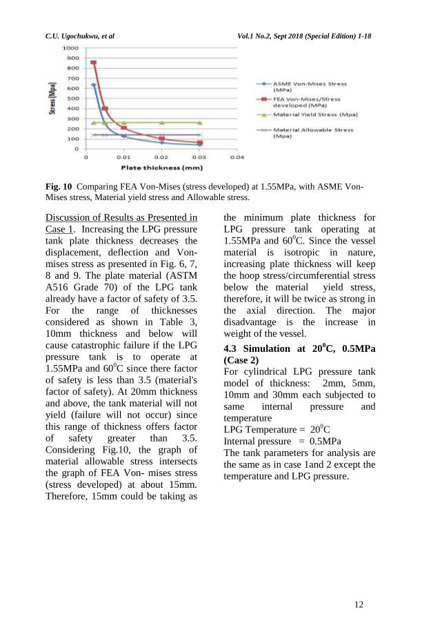
Fig. 10 Comparing FEA Von-Mises (stress developed) at 1.55MPa, with ASME Von-
Mises stress, Material yield stress and Allowable stress.
Discussion of Results as Presented in
Case 1. Increasing the LPG pressure
tank plate thickness decreases the
displacement, deflection and Von-
mises stress as presented in Fig. 6, 7,
8 and 9. The plate material (ASTM
A516 Grade 70) of the LPG tank
already have a factor of safety of 3.5.
For the range of thicknesses
considered as shown in Table 3,
10mm thickness and below will
cause catastrophic failure if the LPG
pressure tank is to operate at
1.55MPa and 600C since there factor
of safety is less than 3.5 (material's
factor of safety). At 20mm thickness
and above, the tank material will not
yield (failure will not occur) since
this range of thickness offers factor
of safety greater than 3.5.
Considering Fig.10, the graph of
material allowable stress intersects
the graph of FEA Von- mises stress
(stress developed) at about 15mm.
Therefore, 15mm could be taking as
the minimum plate thickness for
LPG pressure tank operating at
1.55MPa and 600C. Since the vessel
material is isotropic in nature,
increasing plate thickness will keep
the hoop stress/circumferential stress
below the material yield stress,
therefore, it will be twice as strong in
the axial direction. The major
disadvantage is the increase in
weight of the vessel.
4.3 Simulation at 200C, 0.5MPa
(Case 2)
For cylindrical LPG pressure tank
model of thickness: 2mm, 5mm,
10mm and 30mm each subjected to
same internal pressure and
temperature
LPG Temperature = 200C
Internal pressure = 0.5MPa
The tank parameters for analysis are
the same as in case 1and 2 except the
temperature and LPG pressure.
12
Page 13
C.U. Ugochukwu, et al Vol.1 No.2, Sept 2018 (Special Edition) 1-18
(a) (b)
(c) (d)
Fig. 11 Application of 0.5MPa at 200C , 10mm thickness (a) Von-Mises stress (b)
displacement in x-axis (c)displacement in y-axis (d) deflection (z-axis).
4.4 Results and Discussion as
Presented in Case 2
Results. Figure 11 shows the
ANSYS static structural contour
plots of the LPG pressure tank at
0.5MPa and 200C. Figure 11 (b) and
(c) shows the displacement in x and
y direction while (d) shows the
deflection in z direction. Plots in red
are area where the biaxial state stress
is mostly felt. These results are
presented in tabular form as shown in
Table 6. Graphical presentation of
these results is similar to Fig. 6,7 and
8. Table7 follow the same trend as
presented in Table 3 of case 1.
13
Page 14
C.U. Ugochukwu, et al Vol.1 No.2, Sept 2018 (Special Edition) 1-18
Table 6 Displacements and deflections at different plate thickness for cylindrical LPG
pressure tank at 0.5MPa, 200C
PLATE
THICKNESS
(mm)
DISPLACEMENT
IN X-AXIS
(mm)
DISPLACEMENT
IN Y-AXIS
(mm)
DEFLECTION
(Z-AXIS)
(mm)
2 0.604060 1.176200 1.467600
5 0.258000 0.410780 0.763770
10 0.063712 0.111730 0.159030
30 0.041815 0.077964 0.092854
Table:7 ASME Stress, FEA stress and Factor of Safety at different plate thickness
for LPG at 0.5MPa, 200C
PLATE
THICKNESS
(mm)
FEA Von-Mises/Stress
developed (MPa)
ASME Von-Mises
stress (MPa)
(FEA) Factor of
Safety
2 276.61 205.68 1.75
5 129.36 82.28 3.75
10 33.196 41.14 14.61
30 20.722 13.71 23.41
Fig. 12 Comparing FEA Von-Mises (stress developed) at 0.5MPa with ASME Von-
Mises stress, Material yield stress and Allowable stress.
Discussion of results as presented in
simulation case 2. Displacement,
deflection, Von-mises stress and the
factor of safety follow the same trend
as simulation case 1. The FEA Von-
mises stress that is the stress
developed shows some correlation
with the ASME Von-mises stress. In
Table 6, the deflections are more
than displacement values since the
hoop stresses often results to bending
of the vessel plate material.
Considering Table 7, at 5mm
thickness, the finite element factor of
safety (3.75) is greater than the
material's factor of safety (3.5). Also,
this is illustrated graphically in
Figure 12 in which the graph of
14
Page 15
C.U. Ugochukwu, et al Vol.1 No.2, Sept 2018 (Special Edition) 1-18
material allowable stress intersets the
graph of FEA Von-mises stress at
5mm. Therefore, it can said that at
LPG pressure of 0.5MPa and
ambient temperature of 200C, the
minimum plate thickness
recommended is 5mm.
4.5 Simulation at 400C, 0.91MPa
(Case 3)
The same range of thickness was
maintained (2mm, 5mm, 10mm,
20mm and 30mm), tank material
properties remains the same but
operating temperature and pressure
was changed.
LPG Temperature = 400C
Internal pressure = 0.91MPa
Table 4 Displacements and deflection at different plate thickness for cylindrical LPG
pressure tank at 0.91MPa, 400C
PLATE
THICKNESS
(mm)
DISPLACEMENT
IN X-AXIS
(mm)
DISPLACEMENT
IN Y-AXIS (mm)
DEFLECTION
(Z-AXIS)
(mm)
2 1.099400 2.14060 2.67100
5 0.470400 0.74904 1.39510
10 0.234690 0.36303 0.66072
20 0.115960 0.20335 0.28944
30 0.076102 0.14189 0.16899
Table 5 ASME stress, FEA stress and Factor of Safety at different plate thickness for
LPG at 0.91MPa, 400C
PLATE
Thickness
(mm)
FEA Von-
Mises/Stress
developed (MPa)
ASME Von-Mises
stress (MPa)
(FEA) Factor
of Safety
2 503.430 374.34 0.96
5 235.480 149.74 2.06
10 122.530 74.87 3.96
20 60.417 37.44 8.03
30 37.714 24.96 12.86
15
Page 16
C.U. Ugochukwu, et al Vol.1 No.2, Sept 2018 (Special Edition) 1-18
Fig. 13 Comparing FEA Von-Mises (stress developed) at 0.91MPa with ASME Von-
Mises stress, Material yield stress and Allowable stress.
4.6 Results and Discussion as
Presented in Case 3
Table 4 and 5 follows the trend of
case 1 and 2. Figure 13 shows the
non linear relationship between stress
and plate thickness. It also shows the
convergence of finite element Von-
mises stress(stress developed) and
ASME Von-mises stress. The inverse
relationship between thickness and
stress is due to the disparity between
circumferential stress (hoop stress)
and plate thickness. Since the tank
material is usually welded, therefore
the welded area experience HAZ
(heat-affected-zone). As pressure
increases, hoop stress builds up in
the heat-affected-zone, leading to
crack initiation, propagation and
material failure. This will occur once
the stress developed is above the
material allowable stress. For the
range of thickness considered, 10mm
thickness is taking as the minimum
plate thickness at 0.91MPa since it
offers factor of safety greater than
the material's factor of safety. In
Figure 11, the graph of material
allowable stress intersects the graph
of FEA Von-Mises stress at 10mm
thickness showing that failure will
not occur at this thickness and above
it.
5. Conclusion The Von-Mises stress and
displacement in the Liquefied
petroleum gas (LPG) pressure tank
under different pressure distribution
and ambient condition has been
obtained using the finite element
method. As temperature increases,
LPG pressure increases, hence, there
is need to design the pressure tank in
such a way that the thickness will
accommodate the rise in pressure.
This will yield better results and
reduce the risk of an explosion. For
the different pressure range
considered: 0.5MPa, 0.91MPa and
1.55MPa, the Von-Mises stress
decreases with increasing plate
thickness. A minimum plate
thickness was deduced for each
pressure range: 5mm thickness for
0.5MPa, 10mm thickness for
0.91MPa and 15mm thickness for
1.55MPa. At this minimum plate
thickness, the Von-Mises stresses
were found to be lower than the tank
material allowable stress
(138MN/m2). The finite element
Von-mises stress developed during
simulation were in the same range
with the ASME Von-mises. The
range of thickness and stress are in
compliance with ASME section VIII
division 1 part ULT. The vessel
material ASTM A516 Grade 70
already has a factor of safety of 3.5;
therefore, design consideration
should include material's yield and
allowable stress and factor of safety
greater than 3.5. For this research
work, there are different possible
scenarios. Once the boundary
condition changes, the result will
change, therefore, each should be
treated as a case study. The effect of
weldment along the seams of the
vessel was not carried out in this
work.
References [1] Foraminifera Market Research.
Liquefied Petroleum Gas Bulk
Storage and Marketing in
Nigeria; How Viable? Retrieved
February 10th 2017 from
16
Page 17
C.U. Ugochukwu, et al Vol.1 No.2, Sept 2018 (Special Edition) 1-18
http://www.foramfera.com/lique
fied- petroleum-gas-bulk-
storage-and-marketing-in-
nigeria-how-viable/. (2017)
[2] Bruce G. The Smell of Danger.
Chemmatters. Journal of
American Chemical
Society.Retrieved February 2nd
2017 from
http://brucegoldfarb.com/clips/
GoldfarbPropane.pdf. (1988).
[3] Abdul-Kadir K. A. Domestic
LPG Market Growth-
Infrastructural Challenges and
Opportunities. Retrieved
02/02/17 from
http://nigerialpgas.com/downloa
ds/Domestic_LPG_Market_Gro
wth_Infrastructural_Challenges
_and_Opportunities.p df.
(2016).
[4] Dennis R.M. Pressure Vessel
Design Manual: Illustrated
Procedures for Solving Major
Pressure Vessel Design
Problems, New York: Gulf
Professional Publishing. pp. 10-
109. (2004).
[5] Dražan K., Ivan S., Antun S.,
Željko I. and Darko D. Stress
Analyses of Cylindrical Vessel
with Changeable Head
Geometry. Scientific Bulletin,
Series C, Volume XXIII,
Fascicle: Mechanics, Tribology,
Machine Manufacturing
Technology. ISSN 1224-3264.
(2009).
[6] Adeyefa O. and Oluwole. O.
Finite Element Modeling of
Variable Membrane Thickness
for FieldnFabricated Spherical
(LNG) Pressure Vessels.
http://www.scirp.org/journal/en
g. (2013).
[7] ASME. ASME Boiler and
Pressure Vessel Codes. The
American Society of
Mechanical Engineers, New
york. Library of Congress
Catalog Card Number 56-3934.
(2004).
[8] Oluwole O and Emagbetere E.
Finite Element Analysis of In-
plane Displacements and Von-
Mises Stresses in Ellipsoidal
and Circular Cylindrical
Petroleum Tankers.
(http://www.scirp.org/journal/en
g). (2013).
[9] Awoyinfa S. Two killed, seven
injured in Ogun gas plant
explosion. Punch Newspapaer
Nigeria.
punchng.com/two-killed-
seven-injured-ogun-gas-plant-
explosion/. (2017).
[10] Richard G.B. Advance Strength
and Applied Stress Analysis.
Second edition. McGraw hill
publishing companies Inc.
(1999).
[11] Adeyefa O.A. Finite Element
Analysis of Double-Jacked
Field-Fabricated Spherical
Liquefied Natural Gas (LNG)
Pressure Vessels. Ph.D.
Thesis, University of Ibadan
(2015).
[12] Jorge R.M., Helder S.W. and
Carlos A.C. Stress Analysis on
Vessel/Nozzle Intersections
With/Without Pad
Reinforcement for Cylindrical
Pressure Vessels. Proc. of 19th
Int Congress of Mech.
Engineering, Brasília, DF.
(2007).
[13] Morrish K. and Shankar K.M.
Comparative Stress Analysis of
Elliptical and Cylindrical
Pressure Vessels With and
17
Page 18
C.U. Ugochukwu, et al Vol.1 No.2, Sept 2018 (Special Edition) 1-18
Without Autofrettage
Consideration Using Finite
Element Method. Int. J. Adv.
Engg. Res. Studies/IV/II/, pp.
189-195 (2015).
[14] Young W.K. and Hyochoong B.
Finite Element Method Using
Mathlab, New York: CRC
Press, pp. 307- 373. (1997).
[15] Timoshenko T. and Goodier J.
Theory of Elasticity, New York:
McGraw Hill Books Company
Inc., pp. 255-257.(1951)
[16] Zienkiewicz O.C. and Taylor
R.L. The Finite Element
Method, Oxford: Butterworth-
Heinemann, vol. 2, pp. 111-210.
(2000).
18