Finite Element Analysis on Friction Plate Of a Wet Multiple Clutch by Using Various Friction Materials
1Chadalawada Ramanamma Engineering College, Tirupati, Andhra Pradesh, India 2 Asst. Professor, Dept. of Mechanical Engineering Chadalawada Ramanamma Engineering College, Tirupati,
Andhra Pradesh, India
---------------------------------------------------------------------***---------------------------------------------------------------------Abstract - A clutch is a mechanical device which provides for the transmission of power (and therefore usually motion) from one component (the driving member) to another (driven member).The opposite component of the clutch is the brake. A multi plate clutch may be used when a large torque is to be transmitted .The inside discs are fastened to the driven shaft to permit axial motion. The outside discs are held by bolts and are fastened to the housing which is keyed to the driving shaft. The multi disc clutches are fastened to the driving shaft .The multi discs clutches are extensively used in motor cars, motorbikes, machine tools etc. The aim of the project is to suggest friction lining material for a multi plate clutch by using ANSYS.A 3D drawing is drafted for multi plate clutch from the design calculations and a 3D model is created in the CATIAV5 using different materials like cork,copper,SF001,SFBU. The Project aims to do structural and thermal analysis for evaluating the above design materials for a better friction lining to multiplate 1clutch by using ANSYS 15.0, finally the project concludes that SFBU material has better friction lining compare to other materials. Key Words: Friction Plate, Clutch, Composite Material, Structural Analysis, And Thermal Analysis. 1.INTRODUCTION Clutch is a mechanism for transmitting rotation, which can be engaged and disengaged. Clutches are useful in devices that have two rotating shafts. In these devices, one shaft is typically driven by a motor or pulley, and the other shaft drives another device. Let us take an instance where one shaft is driven by a motor and the other drives a drill chuck. The clutch connects the two shafts so that they can either be locked together and spin at the same speed (engaged), or be decoupled and spin at different speeds (disengaged). Depending on the orientation, speeds, material, torque produced and finally the use of the whole device, different kinds of clutches are used. The clutch in itself is a mechanism, which employs different configurations and different principles in various models available. In the following lines, we have provided the different kinds of clutches that are available.
1.1Different Kinds of Clutches Friction Clutch Friction clutches are used to transmit torque by using the surface friction between two faces. Dog Clutch A dog clutch couples two rotating shafts or other rotating components by interference. Both the parts of the clutch are designed so that one pushes into the other, causing both to rotate.
Cone Cutch Cone clutches are nothing, but frictional clutches with conical surfaces. The conical surface provides a taper, which means that given actuating force brings the surfaces of the clutch into contact and rotates
Overrunning Clutch Also known as the freewheel mechanisms, this type of clutch disengage the driveshaft from the driven shaft, when the driven shaft rotates faster than the driveshaft.
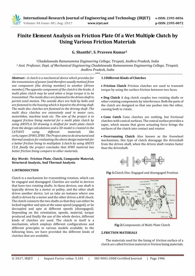
Fig-1:Clutch Disc-Engaged and disengaged Position
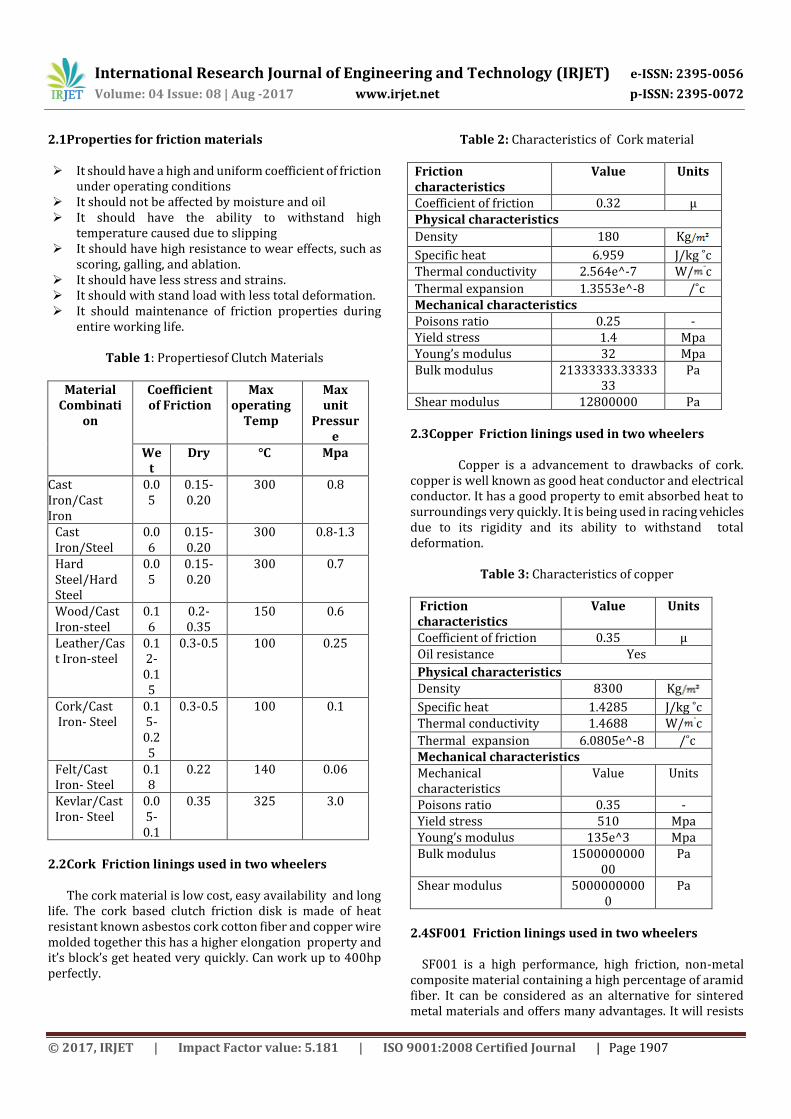
Fig-2:Components of Multi-Plate Clutch
2.FRICTION MATERIALS The materials used for the lining of friction surface of a clutch are called friction material or friction lining materials.
2.1Properties for friction materials It should have a high and uniform coefficient of friction
under operating conditions It should not be affected by moisture and oil It should have the ability to withstand high
temperature caused due to slipping It should have high resistance to wear effects, such as
scoring, galling, and ablation. It should have less stress and strains. It should with stand load with less total deformation. It should maintenance of friction properties during
entire working life.
Table 1: Propertiesof Clutch Materials
Material Combinati
on
Coefficient of Friction
Max operating
Temp
Max unit
Pressure
Wet
Dry °C Mpa
Cast Iron/Cast Iron
0.05
0.15-0.20
300 0.8
Cast Iron/Steel
0.06
0.15-0.20
300 0.8-1.3
Hard Steel/Hard Steel
0.05
0.15-0.20
300 0.7
Wood/Cast Iron-steel
0.16
0.2-0.35
150 0.6
Leather/Cast Iron-steel
0.12-0.15
0.3-0.5 100 0.25
Cork/Cast Iron- Steel
0.15-0.25
0.3-0.5 100 0.1
Felt/Cast Iron- Steel
0.18
0.22 140 0.06
Kevlar/Cast Iron- Steel
0.05-0.1
0.35 325 3.0
2.2Cork Friction linings used in two wheelers The cork material is low cost, easy availability and long life. The cork based clutch friction disk is made of heat resistant known asbestos cork cotton fiber and copper wire molded together this has a higher elongation property and it’s block’s get heated very quickly. Can work up to 400hp perfectly.
Table 2: Characteristics of Cork material
Friction characteristics
Value Units
Coefficient of friction 0.32 µ Physical characteristics
Density 180 Kg
Specific heat 6.959 J/kg ˚c Thermal conductivity 2.564e^-7 W/ c
Shear modulus 12800000 Pa 2.3Copper Friction linings used in two wheelers Copper is a advancement to drawbacks of cork. copper is well known as good heat conductor and electrical conductor. It has a good property to emit absorbed heat to surroundings very quickly. It is being used in racing vehicles due to its rigidity and its ability to withstand total deformation.
Table 3: Characteristics of copper
Friction characteristics
Value Units
Coefficient of friction 0.35 µ Oil resistance Yes
Physical characteristics Density 8300 Kg
Specific heat 1.4285 J/kg ˚c Thermal conductivity 1.4688 W/ c
2.4SF001 Friction linings used in two wheelers SF001 is a high performance, high friction, non-metal composite material containing a high percentage of aramid fiber. It can be considered as an alternative for sintered metal materials and offers many advantages. It will resists
International Research Journal of Engineering and Technology (IRJET) e-ISSN: 2395-0056
Volume: 04 Issue: 08 | Aug -2017 www.irjet.net p-ISSN: 2395-0072
high energy inputs and is suitable for both dry and oil -immersed applications. It is not abrasive to the counter material, is silent in operation and it will resists high pressures. The wear rate is low even at high temperatures. SF-001 is available in thicknesses from 0.6mm to 5mm
Table 4: Characteristics of SF001
Friction characteristics
Value Units
Coefficient of friction 0.45 µ Wear rate 40±10
Fading 400±10 ˚C Physical characteristics Density 1350 Kg
Specific heat 4.43 J/kg ˚c Thermal conductivity 68.25 W/ c
Poisons ratio 0.49 - Yield stress 68 Mpa Young’s modulus 7000 Mpa Bulk modulus 116666666666.667 Pa Shear modulus 2348993288.5906 Pa
2.5SFBU Friction linings used in two wheelers
SF-BU is a high performance, high friction, non-metal composite material containing a high percentage of aramid fiber. It is similar to SF-001 but with a higher Kevlar composition in order to increase friction characteristics.
Table 5: Characteristics of SF BU
Friction characteristics
Value Units
Coefficient of friction 0.45 µ Wear rate 50±10
Fading 390±10 ˚C Physical characteristics Density 1250 Kg
Specific heat 3.35 J/kg ˚c Thermal conductivity 68.25 W/ c
Poisons ratio 0.49 - Yield stress Mpa Young’s modulus 7260 Mpa Bulk modulus 121000000000 Pa Shear modulus 2436241610.738
26 Pa
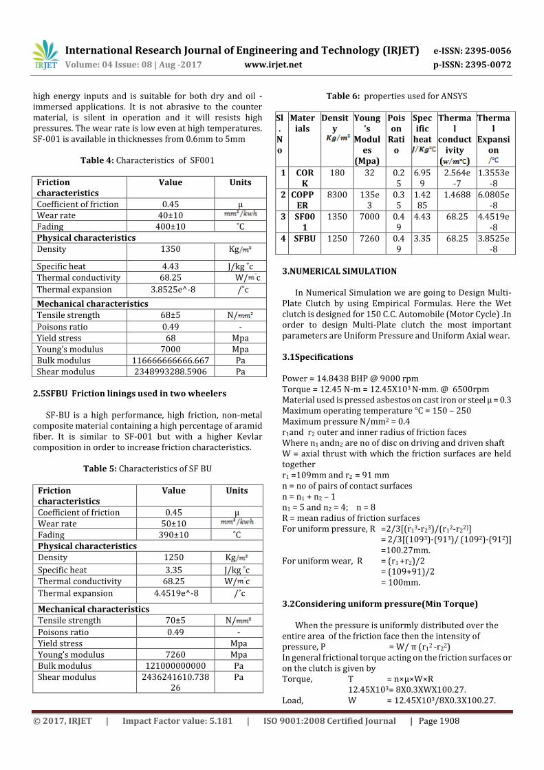
Table 6: properties used for ANSYS
Sl.
No
Materials
Density
Young’s
Modules
(Mpa)
Poison
Ratio
Specific
heat
Thermal
conductivity
( )
Thermal
Expansion
1 COR
K 180 32 0.2
5 6.95
9 2.564e
-7 1.3553e
-8 2 COPP
ER 8300 135e
3 0.35
1.4285
1.4688 6.0805e-8
3 SF001
1350 7000 0.49
4.43 68.25 4.4519e-8
4 SFBU 1250 7260 0.49
3.35 68.25 3.8525e-8
3.NUMERICAL SIMULATION
In Numerical Simulation we are going to Design Multi-Plate Clutch by using Empirical Formulas. Here the Wet clutch is designed for 150 C.C. Automobile (Motor Cycle) .In order to design Multi-Plate clutch the most important parameters are Uniform Pressure and Uniform Axial wear.
3.1Specifications Power = 14.8438 BHP @ 9000 rpm Torque = 12.45 N-m = 12.45X10³ N-mm. @ 6500rpm Material used is pressed asbestos on cast iron or steel µ = 0.3 Maximum operating temperature °C = 150 – 250 Maximum pressure N/mm2 = 0.4 r1and r2 outer and inner radius of friction faces Where n1 andn2 are no of disc on driving and driven shaft W = axial thrust with which the friction surfaces are held together r1 =109mm and r2 = 91 mm n = no of pairs of contact surfaces n = n1 + n2 – 1 n1 = 5 and n2 = 4; n = 8 R = mean radius of friction surfaces For uniform pressure, R =2/3[(r1
3-r23)/(r1
2-r22)]
= 2/3[(1093)-(913)/ (1092)-(912)] =100.27mm.
For uniform wear, R = (r1 +r2)/2 = (109+91)/2 = 100mm. 3.2Considering uniform pressure(Min Torque)
When the pressure is uniformly distributed over the
entire area of the friction face then the intensity of pressure, P = W/ π (r1
2 -r22)
In general frictional torque acting on the friction surfaces or on the clutch is given by Torque, T = n×µ×W×R 12.45X103= 8X0.3XWX100.27. Load, W = 12.45X10³/8X0.3X100.27.
International Research Journal of Engineering and Technology (IRJET) e-ISSN: 2395-0056
Volume: 04 Issue: 08 | Aug -2017 www.irjet.net p-ISSN: 2395-0072
When the pressure is uniformly distributed over the entire area of the friction face then the intensity of pressure
P = W/ π (r12 -r2
2) Frictional torque acting on the friction surface or on the clutch T = µWR 12.45×103=0.3×W×100.27 W = 413.8825 N. Pressure, P = W/ π (r1
2 -r22)
= 413.8825/ π (1092- 912) P = 0.03659N/mm2.
3.4Considering uniform axial wear For uniform wear P×r=C (C=Constant) Axial force required to engage the clutch W = 2πC (r1-r2) Mean radius of the friction surfaces R =(109+91)/2=100 Torque transmitted T = n×µ×W×R 12.45X103= 8X0.3XWX100 Load, W = 12.45X10³/8X0.3X100. W = 51.873N. The intensity of pressure is maximum at the inner radius (r2) of the friction or contact surface Equation may be written as
Pmax×r2=C
That total force acting on the friction surface C =W/(2π (r1-r2 ) = 51.875/ (2×3.1415(109-91)
The intensity of pressure is minimum at the outer radius
(r1) of the friction or contact surface Equation may be written as Pmin×r1=C Pmin=C/r1 = 0.4586/109 = 0.0042073 Mpa The average pressure (Pavg) on the friction or contact surface is given by Pavg=( total force on friction surfaces/(cross sectional area of surface) Pavg =W/ π (r1
2 -r22)
=51.875/π (1092 -912) Pavg =0.0045867Mpa
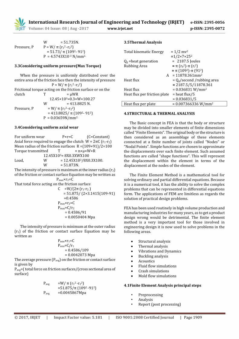
3.5Thermal Analysis Total kinematic Energy = 1/2 mv2 =1/2×7×252 Qg =heat generation = 2187.5 Joules Rubbing Area = π (r0
The Basic concept in FEA is that the body or structure may be divided into smaller elements of finite dimensions called “Finite Elements”. The original body or the structure is then considered as an assemblage of these elements connected at a finite number of joints called “Nodes” or “Nodal Points”. Simple functions are chosen to approximate the displacements over each finite element. Such assumed functions are called “shape functions”. This will represent the displacement within the element in terms of the displacement at the nodes of the element.
The Finite Element Method is a mathematical tool for
solving ordinary and partial differential equations. Because it is a numerical tool, it has the ability to solve the complex problems that can be represented in differential equations form. The applications of FEM are limitless as regards the solution of practical design problems. FEA has been used routinely in high volume production and manufacturing industries for many years, as to get a product design wrong would be detrimental. The finite element method is a very important tool for those involved in engineering design it is now used to solve problems in the following areas.
4.1.1.Preprocessing Pre-processing is the stage in which preliminary decision
have to take they are defining element type, analysis type, type of mesh, material properties etc.,
The pre-processor stage involves the following • Specify the title, which is the name of the problem. • Setting the type of analysis to be used. • Creating the model. It can be imported from another CAD
drafting package via a neutral file format. • Defining element type, these chosen from element
library. • Assigning real constants and material properties like
• Apply mesh. Mesh generation is the process of dividing the analysis continuum into number of discrete parts of finite elements.
4.1.2.Engineering data
1. Choose menu path Main Menu> engineering data > name of material> Material properties>save project >return project. The Define Material Model Behavior dialog box appears.
2. In the Material Models Available window, double-click on the icons next to the following options: Structural, Linear, Elastic, and Isotropic. A dialog box appears.
3. Enter YOUNG’S MODULUS value. 4. Enter Poisson ratio value. 5. Enter DENSITY value. 6. Click on OK. Material Model Number 1 appears in the
Material Models Defined window on the left. 7. Choose menu path Material> Exit to remove the Define
Material Model Behaviour dialog box.
4.1.3Geometry Choose menu path Main Menu> Geometry > import igs
file > generate>save project >return project.
Check the dimensions of designed object. 4.1.4Model
Choose menu path Main Menu> Model> Meshing>
Analysis >Solution>Results. In meshing we apply the fine type of mesh. It’s give no
of elements and nodes. After meshing we do the analysis settings. In analysis
setting we apply the boundary condition. Now we find the solutions like elastic strain, von-misses
stress ,total deformation ,shear stress ,shear strain. Save project.
4.1.5Report (post processing )
After complete the solution ansys give a final report. In this report it explains which steps we follow in ansys
and show results. In plot graphs based on program control. Print the project report .
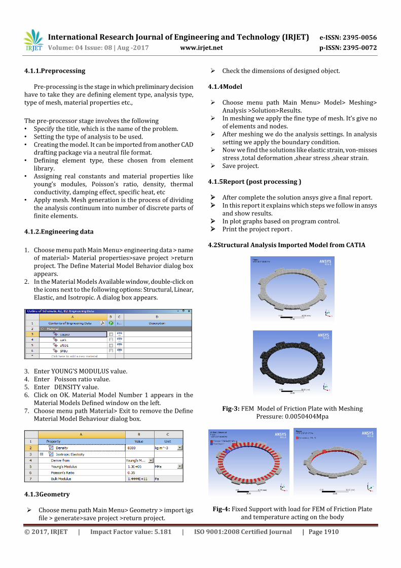
4.2Structural Analysis Imported Model from CATIA
Fig-3: FEM Model of Friction Plate with Meshing Pressure: 0.0050404Mpa
Fig-4: Fixed Support with load for FEM of Friction Plate and temperature acting on the body
International Research Journal of Engineering and Technology (IRJET) e-ISSN: 2395-0056
Volume: 04 Issue: 08 | Aug -2017 www.irjet.net p-ISSN: 2395-0072
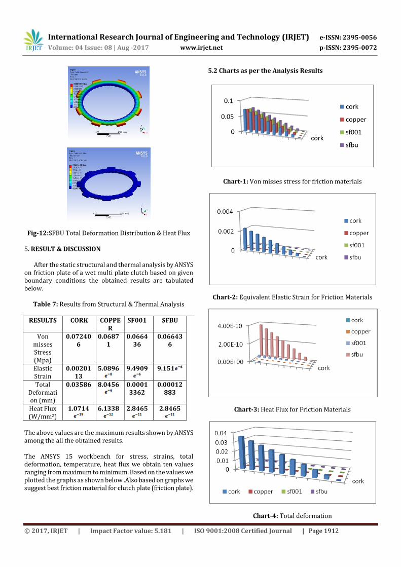
Fig-12:SFBU Total Deformation Distribution & Heat Flux 5. RESULT & DISCUSSION
After the static structural and thermal analysis by ANSYS on friction plate of a wet multi plate clutch based on given boundary conditions the obtained results are tabulated below.
Table 7: Results from Structural & Thermal Analysis
RESULTS CORK COPPE
R SF001 SFBU
Von misses Stress (Mpa)
0.072406
0.06871
0.066436
0.066436
Elastic Strain
0.0020113
5.0896
9.4909
9.151
Total Deformation (mm)
0.03586 8.0456
0.00013362
0.00012883
Heat Flux (W/mm2)
1.0714
6.1338
2.8465
2.8465
The above values are the maximum results shown by ANSYS among the all the obtained results. The ANSYS 15 workbench for stress, strains, total deformation, temperature, heat flux we obtain ten values ranging from maximum to minimum. Based on the values we plotted the graphs as shown below .Also based on graphs we suggest best friction material for clutch plate (friction plate).
5.2 Charts as per the Analysis Results
cork0
0.05
0.1cork
copper
sf001
sfbu
Chart-1: Von misses stress for friction materials
Chart-2: Equivalent Elastic Strain for Friction Materials
Chart-3: Heat Flux for Friction Materials
Chart-4: Total deformation
International Research Journal of Engineering and Technology (IRJET) e-ISSN: 2395-0056
Volume: 04 Issue: 08 | Aug -2017 www.irjet.net p-ISSN: 2395-0072
Structural analysis and Thermal analysis is done on the friction plates to verify the strength& temperature distribution of different Friction materials used are Cork , Copper,SF001 ,SFBU and CFRP Powder Metal. Material used for inner disc is steel and outer disc is bronze. By observing the analysis results, design is safe. Total Deformation and stress values are less using SFBU powder Metal than using cork, copper and SF001.Hence we conclude that for multi plate clutches using SFBU powder metal as friction material Strength is Improved, Deformation is reduced and temperature distribution and heat flux also improved and Material Life of the Clutch is improved.
6.SCOPE OF FUTURE WORK 2D and 3D Computations were carried out for multi-plate clutch in present analysis. Some of the suggested work is outlined below Modal analysis can be generated for multi-plate clutch. Linear bulking analysis for different loads acting on
multi plate clutch Rigid dynamic analysis to performed on dynamic
conditions For the present case only computations were
performed. Fabrication work can be carried out. 7.REFERENCES [1] A. Nelson; 2009; Engineering Mechanics; New Edition;
Tata McGraw Hill Education. [2] C.P.Kothandaraman;S.Subramanyan;Heat& Mass
Transfer Data Book; Sixth Edition; New Age Publications
[3] H. Kitabayashi, C. Li and H. Hiraki, “Analysis of the various factors affecting drag torque in multi-plate wet clutches”, SAE paper, No. 2003-01-1973, 2003.
[4] Pandya and Shah; 2005; Machine Design; Charotar. [5] R.S.Khurmi; J.K.Gupta; 2005; Theory of Machines; New