ORIGINAL ARTICLE Finite element modeling the influence of edge roundness on the stress and temperature fields induced by high-speed machining Tuğrul Özel & Erol Zeren Received: 28 March 2006 / Accepted: 7 July 2006 / Published online: 6 October 2006 # Springer-Verlag London Limited 2006 Abstract High-speed machining (HSM) may produce parts at high production rates with substantially higher fatigue strengths and increased subsurface micro-hardness and plastic deformation, mostly due to the ploughing of the round cutting tool edge associated with induced stresses, and can have far more superior surface properties than surfaces generated by grinding and polishing. Cutting edge roundness may induce stress and temperature fields on the machined subsurface and influence the finished surface properties, as well as tool life. In this paper, a finite element method (FEM) modeling approach with arbitrary Lagrangian Eulerian (ALE) fully coupled thermal-stress analysis is employed. In order to realistically simulate HSM using edge design tools, an FEM model for orthogonal cutting is designed, and solution techniques such as adaptive meshing and explicit dynamics are performed. A detailed friction modeling at the tool–chip and tool–work interfaces is also carried out. Work material flow around the round edge cutting tool is successfully simulated without implementing a chip separation criterion and without the use of a remeshing scheme. The FEM modeling of the stresses and the resultant surface properties induced by round edge cutting tools is performed for the HSM of AISI 4340 steel. Once FEM simulations are complete for different edge radii and depths of cut, the tool is unloaded and the stresses are relieved. Predicted stress fields are compared with experi- mentally measured residual stresses obtained from the literature. The results indicate that the round edge design tools influence the stress and temperature fields greatly. An optimization scheme can be developed to identify the most desirable edge design by using the finite element analysis (FEA) scheme presented in this work. Keywords Finite element modeling . Edge roundness . Arbitrary Lagrangian Eulerian method . Machining-induced stresses 1 Introduction Predicting the physical process and temperature and stress fields accurately play a pivotal role for predictive process engineering for high-speed machining (HSM) processes. Tool edge geometry is particularly important because its influence on obtaining the most desirable tool life and surface integrity is considered to be significant. Finite element method (FEM) modelling based simulation of machining processes has been providing a better under- standing of chip formation mechanisms, heat generation in cutting zones, and the resulting stress and temperature fields. Advanced process simulation techniques are essential in order to study the influence of the tool edge geometry and cutting conditions on the surface integrity, especially on the machining-induced stresses. In this paper, an advanced FEM simulation technique is utilized to investigate the physical cutting process for predicting the temperature and stress fields on the machined surface. As commonly known, there are two types of analysis in which a continuous medium can be described, i.e., Eulerian and Lagrangian, in the FEM modeling of deformation processes. In a Lagrangian analysis, the computational grid deforms with the material, whereas in an Eulerian analysis, it is fixed in space. The Lagrangian calculation embeds a computational mesh in the material domain and solves for Int J Adv Manuf Technol (2007) 35:255–267 DOI 10.1007/s00170-006-0720-2 T. Özel (*) : E. Zeren Department of Industrial and Systems Engineering, Rutgers University, Piscataway, NJ 08854, USA e-mail: [email protected]
Transcript
ORIGINAL ARTICLE
Finite element modeling the influence of edge roundnesson the stress and temperature fields inducedby high-speed machining
Tuğrul Özel & Erol Zeren
Received: 28 March 2006 /Accepted: 7 July 2006 / Published online: 6 October 2006# Springer-Verlag London Limited 2006
Abstract High-speed machining (HSM) may produce partsat high production rates with substantially higher fatiguestrengths and increased subsurface micro-hardness andplastic deformation, mostly due to the ploughing of theround cutting tool edge associated with induced stresses,and can have far more superior surface properties thansurfaces generated by grinding and polishing. Cutting edgeroundness may induce stress and temperature fields on themachined subsurface and influence the finished surfaceproperties, as well as tool life. In this paper, a finite elementmethod (FEM) modeling approach with arbitrary LagrangianEulerian (ALE) fully coupled thermal-stress analysis isemployed. In order to realistically simulate HSM usingedge design tools, an FEM model for orthogonal cutting isdesigned, and solution techniques such as adaptive meshingand explicit dynamics are performed. A detailed frictionmodeling at the tool–chip and tool–work interfaces is alsocarried out. Work material flow around the round edgecutting tool is successfully simulated without implementinga chip separation criterion and without the use of aremeshing scheme. The FEM modeling of the stresses andthe resultant surface properties induced by round edgecutting tools is performed for the HSM of AISI 4340 steel.Once FEM simulations are complete for different edge radiiand depths of cut, the tool is unloaded and the stresses arerelieved. Predicted stress fields are compared with experi-mentally measured residual stresses obtained from theliterature. The results indicate that the round edge designtools influence the stress and temperature fields greatly. An
optimization scheme can be developed to identify the mostdesirable edge design by using the finite element analysis(FEA) scheme presented in this work.
Keywords Finite element modeling . Edge roundness .
Arbitrary Lagrangian Eulerian method .
Machining-induced stresses
1 Introduction
Predicting the physical process and temperature and stressfields accurately play a pivotal role for predictive processengineering for high-speed machining (HSM) processes.Tool edge geometry is particularly important because itsinfluence on obtaining the most desirable tool life andsurface integrity is considered to be significant. Finiteelement method (FEM) modelling based simulation ofmachining processes has been providing a better under-standing of chip formation mechanisms, heat generation incutting zones, and the resulting stress and temperature fields.Advanced process simulation techniques are essential inorder to study the influence of the tool edge geometry andcutting conditions on the surface integrity, especially on themachining-induced stresses. In this paper, an advanced FEMsimulation technique is utilized to investigate the physicalcutting process for predicting the temperature and stressfields on the machined surface.
As commonly known, there are two types of analysis inwhich a continuous medium can be described, i.e., Eulerianand Lagrangian, in the FEM modeling of deformationprocesses. In a Lagrangian analysis, the computational griddeforms with the material, whereas in an Eulerian analysis,it is fixed in space. The Lagrangian calculation embeds acomputational mesh in the material domain and solves for
Int J Adv Manuf Technol (2007) 35:255–267DOI 10.1007/s00170-006-0720-2
T. Özel (*) : E. ZerenDepartment of Industrial and Systems Engineering,Rutgers University,Piscataway, NJ 08854, USAe-mail: [email protected]
the position of the mesh at discrete points in time. In thoseanalyses, two distinct methods, the implicit and the explicittime integration techniques, can be utilized. The implicittechnique is more applicable to solving linear staticproblems, while the explicit method is more suitable fornon-linear dynamic problems.
A majority of earlier numerical models have relied onthe Lagrangian formulation [1–6], whereas some of themodels utilized the Eulerian formulation [7]. However, itwas evident that the Lagrangian formulation required acriterion for the separation of the undeformed chip from theworkpiece. For this purpose, several chip separationcriteria, such as the strain energy density and the effectivestrain criteria, were implemented as exclusively reported in[8]. Updated Lagrangian implicit formulation with auto-matic remeshing without using chip separation criteria hasalso been used in the simulation of continuous andsegmented chip formation in machining processes [9–16].
The arbitrary Lagrangian Eulerian (ALE) techniquecombines the features of pure Lagrangian analysis andEulerian analysis. ALE formulation is also utilized insimulating machining to avoid frequent remeshing for chipseparation [17–23]. Explicit dynamic ALE formulation isvery efficient for simulating highly non-linear problemsinvolving large localized deformations and changingcontact conditions, such as those experienced in machining.The explicit dynamic procedure performs a large number ofsmall time increments efficiently. The adaptive meshingtechnique does not alter the elements or connectivity of themesh. This technique allows free boundary conditionswhereby only a small part of the workpiece in the vicinityof the tool tip needs to be modeled.
On the other hand, the friction in metal cutting plays animportant role in the thermo-mechanical chip flow andintegrity of the machined work surface. The most commonapproach in modeling the friction at the chip–tool interfaceis to use an average coefficient of friction. Late modelsconsist of a sticking region for which the friction force isconstant, and a sliding region for which the friction forcevaries linearly according to Coulomb’s law.
FEM simulation of machining using edge design tools isessential in order to predict realistic stress and temperaturefields occurring in HSM. Recent FEM studies reported inthe literature include the effects of edge geometries in theorthogonal cutting process [24, 25], simulation of machin-ing non-homogenous materials [26], and predicting stresseson the machined surfaces of hardened steels [27–29].Recently, Guo and Wen [30] used FEM simulations toinvestigate the effects of stagnation and round edgegeometry on chip morphology and stress and temperaturefields on the machined surface. Davies et al. [31]investigated the effects of work material models on thepredictions of the FEM simulations. Deshayes et al. [32]
simulated the serrated chip formation in orthogonal ma-chining and presented comparisons with experimentalresults.
The round edge of the cutting tool and the highlydeformed region underneath has a dominant influence onthe residual stresses of the machined surface. This alsosignifies the proposed work when compared with the earlierFEM modeling studies that relied on chip–workpieceseparation criteria. The use of a separation criterion under-mines the effect of the cutting edge on the residual stressformation on the machined surface.
In this paper, ALE formulation with pure Lagrangianboundaries is applied in the simulation of machining withround edge cutting tools and by utilizing an adaptivemeshing technique. The work material is allowed to flowaround the round edge of the cutting tool so that thephysical process can be simulated more realistically.
2 Orthogonal machining of AISI 4340 steel
In this study, the finite element analysis (FEA) ofmachining-induced temperature and stress fields in theorthogonal cutting of AISI 4340 steel with round carbideedge cutting tools are investigated. An experimental studyconducted by Jacobus et al. [33], where the orthogonalcutting of tubes was performed, is utilized in order tovalidate the predicted machining-induced residual stresses.In their experimental design, Jacobus et al. [33] varied thetool edge roundness, uncut chip thickness (depth of cut),and used a constant cutting speed of 300 m/min, as shownin Table 1. The uncoated tungsten carbide tool with the toolholder provided a 3° rake angle and an 8° clearance angle.All of the cutting conditions revealed orthogonal machiningwith continuous chip formation [33].
2.1 Work material constitutive modeling
In FEA, accurate flow stress models are considered to behighly necessary to represent work material constitutivebehavior under high-strain-rate deformation conditions. Theconstitutive model proposed by Johnson and Cook [34]describes the flow stress of a material with the product of
strain, strain rate, and temperature effects that are individ-ually determined as given in Eq. 1:
σ ¼ Aþ B "ð Þn½ � 1þ C ln"�
"0�
!" #1� T� Troom
Tmelt � Troom
� �m� �
ð1ÞIn the Johnson-Cook (J-C) model, the constant A is, in fact,the initial yield strength of the material at room temperatureand a strain rate of 1/s and " represents the plasticequivalent strain. The strain rate "
�is normalized with a
reference strain rate "0�Temperature term in the J-C model
reduces the flow stress to zero at the melting temperature ofthe work material, leaving the constitutive model with notemperature effect. In this study, the FEA of the machiningof AISI 4340 steel in annealed condition is investigated andits J-C material model constants are given in Table 2.
2.2 Variable friction modeling
As commonly accepted, along the tool–chip contact areanear the cutting edge, a sticking region forms, and thefrictional shearing stress at the sticking region, τp, becomesequal to the average shear flow stress at the tool–chipinterface on the chip, kchip, τp=kchip [13]. Over theremainder of the tool–chip contact area, a sliding regionforms, and the frictional shearing stress can be determinedby using a coefficient of friction, μ, (see Fig. 1).
When the normal stress distribution over the rake face isfully defined and the coefficient of friction, μ, is known, thefrictional stress can be determined. The shear stressdistribution on the tool rake face can be represented astwo distinct regions:
– (1) In the sticking region:
τ f xð Þ ¼ τp ¼ kchip and when μσn xð Þ � τp;
0 < x � lpð2aÞ
– (2) In the sliding region:
τ f xð Þ ¼ μσn xð Þ and when μσn xð Þ < τp;
lp < x � lcð2bÞ
The friction characteristics that are calculated with themethodology explained in Özel and Zeren [36] includeparameters of the normal and frictional stress distributionson the tool rake face. Since the length of the stickingregion, lp, and the chip–tool contact length, lc, are notimplemented in the friction model in the FEM simulations,they are not given in Table 3. Instead, a limiting shearfriction model is implemented with the limiting shear stressand friction coefficients that are given in Table 3.
3 Finite element modeling
The essential and desired attributes of continuum-basedFEM models for cutting are: (1) the work material modelshould satisfactorily represent elastic, plastic, and thermo-mechanical behavior of the work material deformationsobserved during the machining process; (2) the FEM modelshould not require chip separation criteria that highlydeteriorate the physical process simulation around the toolcutting edge, especially in the presence of a dominant tooledge geometry, such as a round edge and/or a chamferededge design; (3) interfacial friction characteristics on thetool–chip and tool–work contacts should be modeled highlyaccurately in order to account for additional heat generationand stress developments due to friction.
Table 2 Constants of the Johnson-Cook (J-C) constitutive model forthe work materials [35]
Material A(MPa)
B(MPa)
n C m Tmelt
(°C)
AISI 4340 steel 792.0 510.0 0.26 0.014 1.03 1,520
Fig. 1 Normal and frictional stress distributions on the tool rake face[13]
In this paper, a commercial software code, ABAQUS/Explicit v6.4, and an explicit dynamic ALE modeling ap-proach is used to conduct the FEM simulation of orthogonalcutting considering round tool edge geometry and all of the
above attributes are successfully implemented in the model.The chip formation process is simulated via adaptivemeshing and the plastic flow of work material in the vicinityof the round edge of the tool. Therefore, there is no need for achip separation criterion in the proposed FEM model.
A thermo-mechanical FEM simulation scheme is createdby including tool and workpiece thermal and mechanicalproperties as summarized in Table 4. Both the workpieceand tool models use four-node bilinear displacement andtemperature (CPE4RT) quadrilateral elements and a plane-strain assumption for the deformations occurring during thehigh-speed orthogonal cutting process.
Table 4 Friction characteristics when using an uncoated carbide-cutting tool
AISI 4340 steel
kchip 250 Mpa when μσnðxÞτp; 0 < x � lpμ 0.5 when μσnðxÞ < τp; lp < x � lp
INFLOW
CHIPFLOW
OUTFLOW
TOOL
WORKPIECE
V = V
Euleriany
x
x c
Lagrangian
(a)
CHIP
ToolPositionAtIncipientState
WORKPIECE
y
x
Lagrangian
V = V
T=T
x c
U = U = 0 , T= T x y 0
0
ToolPositionAtSteady-State
(b)
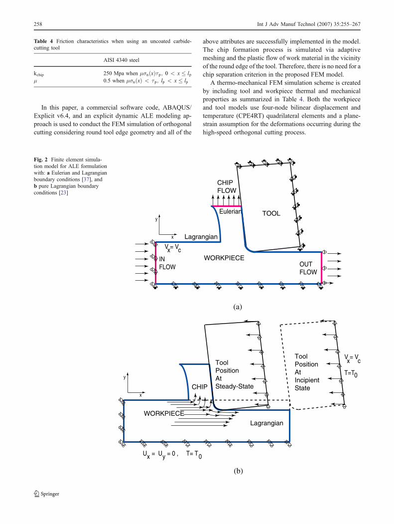
Fig. 2 Finite element simula-tion model for ALE formulationwith: a Eulerian and Lagrangianboundary conditions [37], andb pure Lagrangian boundaryconditions [23]
258 Int J Adv Manuf Technol (2007) 35:255–267
3.1 Arbirtrary Lagrangian Eulerian scheme with Eulerianand Lagrangian boundaries
Initially, an ALE model has been designed in which theworkpiece is also modeled with the Eulerian boundariesfrom the inflow, chip flow, and outflow ends, and with theLagrangian boundaries at the top and the bottom surfaces ofthe workpiece, as shown in Fig. 2a, as explained by the au-thors of [37]. The top surface of the workpiece with the freeboundaries reaches the final deformed shape at the steady-state cutting and it is allowed to deform without restraint.
In this ALE approach, the general governing equationsare solved for both Lagrangian boundaries and Eulerianboundaries in the same fashion. This technique exclusivelycombines the features of pure Lagrangian analysis andEulerian analysis, in which the mesh is fixed spatially andthe material flows through the mesh, as explained earlier.However, this FEM model requires a pre-defined chip
geometry. The chip surfaces are defined with the Lagrang-ian boundary conditions and the chip upper surface isdefined with the Eulerian boundary conditions. Therefore,the chip flow is bound at a vertical position. However, thechip thickness and the chip–tool contact length graduallysettle to their final sizes with the change in the deformationconditions as the cutting reaches its steady state.
The major drawback of this ALE approach is that thepre-defined chip shape must be determined beforehand andentered into the FEM model. Similar ALE models werepresented by Adibi-Sedeh and Mahdavan [21], Haglundet al. [22], and Özel and Zeren [37].
3.2 Arbirtrary Lagrangian Eulerian scheme with pureLagrangian boundaries
An FEM simulation model with ALE scheme with pureLagrangian boundaries is designed and kinematic penalty
Tool advance at 0.05 mm Tool advance at 0.25 mm
Tool unloading Radiation to ambientFig. 3 FEM simulation results using the ALE scheme for machining AISI 4340 steel (test 2)
Int J Adv Manuf Technol (2007) 35:255–267 259
contact conditions between the tool and the workpiece aredefined as shown in Fig. 2b. This model allows an FEMsimulation scheme to simulate the chip formation from theincipient to steady state, as proposed by the authors of [23].In this FEM scheme, the explicit dynamic procedureperforms a large number of small time increments effi-ciently. The adaptive meshing technique does not alter theelements and connectivity of the mesh. This techniquecombines the features of pure Lagrangian analysis, in whichthe mesh follows the material, and Eulerian analysis, whenit is needed as part of the adaptive meshing, in which themesh is fixed spatially and the material flows through themesh. The cutting process as a dynamic event causes largedeformations in several numbers of increments, resulting inmassive mesh distortion and termination of the FEM
simulation. It is highly critical to use adaptive meshingwith fine-tuned parameters in order to simulate the plasticflow over the round edge of the tool. Therefore, theintensity, frequency, and sweeping of the adaptive meshingare adjusted to the most optimum setting for maintaining asuccessful mesh during the simulation of the orthogonalcutting process.
The general equations of motion in explicit dynamicanalysis are integrated by using the explicit centraldifference integration rule with diagonal element massmatrices. The system equations become uncoupled so thateach equation can be solved for explicitly. This makes theexplicit dynamic method highly efficient for non-lineardynamic problems, such as metal cutting. During metalcutting, the flow stress is highly dependent on the
Tool advance at 0.05 mm Tool advance at 0.25 mm
Tool unloading Radiation to ambientFig. 4 FEM simulation results using the ALE scheme for machining AISI 4340 steel (test 4)
260 Int J Adv Manuf Technol (2007) 35:255–267
temperature fields, as discussed earlier. Therefore, fullycoupled thermal-stress analysis is required for accuratepredictions in FEM simulations.
In summary, the explicit dynamic method is used mainlybecause it has the advantages of computational efficiencyfor large deformation and highly non-linear problems, suchas that experienced in machining. Machining, as a coupledthermal-mechanical process, could generate heat to causethermal effects that influence mechanical effects strongly.In the mean time, work material properties changesignificantly as the strain rate and temperature changes.Thus, the fully coupled thermal-stress analysis, in which thetemperature solution and stress solution are also carried outconcurrently, is applied.
4 Simulation results and discussions
Two-dimensional FEM simulations were conducted fortests 1–4 under orthogonal machining conditions byutilizing the proposed ALE with pure Lagrangian bound-aries scheme and the chip formation process from incipientto the steady state was fully observed without implementinga chip–work separation criterion. The workpiece dimen-sions are 1,000 μm in width and 350 μm in height. EachFEM simulation is conducted at three consecutive steps: (1)cutting, (2) tool unloading, and (3) radiation to ambient.The first step includes the chip formation stage fromincipient to steady state; unlike ALE with Lagrangian andEulerian boundaries, all of the boundaries are free and,
Test #1 (Max. 1329 ºC) Test #2 (Max. 1328 ºC)
Test #3 (Max. 1342 ºC) Test #4 (Max. 1385 ºC)Fig. 5 Comparison of predicted temperature fields in four different test conditions
Int J Adv Manuf Technol (2007) 35:255–267 261
therefore, a full-grown chip can be observed. The secondstep involves retracting the tool from the workpiece so thatin-situ process conditions can be computed where the toolis fully unloaded. The third and last steps are the cooling ofthe workpiece by allowing radiation to the ambient. Anatural stress-relief process has been observed which bringsthe machined surface to a state that is the closest possible topredicting realistic residual stresses fields in the workpiece.The FEM simulations have usually taken about 12 hours ona workstation equipped with an Intel Pentium 4 processor.It should be noted that the use of dual and faster processorsmight significantly reduce the computation time. Meshconnectivity without remeshing can be maintained for asubstantial cutting length if the mesh density is increasedaccordingly.
4.1 Influence of edge roundness on temperature fields
The heat generated at the secondary deformation zone andat the tool–chip interface is conducted to the cutting tooland radiation to the ambient is also allowed during thecutting step. Temperature fields that have been obtained atthe tool advances of 0.05 mm and 0.25 mm, during the toolunloading and cooling steps, respectively, are shown inFigs. 3 and 4, respectively. Temperature rises in the primaryand secondary deformation zones are high and reach asteady state very rapidly. The maximum temperatures of1,106°C, 1,315°C, 1,222°C, and 824°C are predicted,respectively, for the process steps under the cutting con-ditions of test 2, as given in Fig. 3. Similarly, the maximumtemperatures of 954°C, 1,385°C, 1,350°C, and 1,285°C are
predicted, respectively, for the process steps under thecutting conditions of test 4, as given in Fig. 4. However, themaximum temperatures are only effective on a concentratedspot at the tool–chip interface, whereas the temperaturefields indicate a temperature distribution around the cuttingzone.
Temperature fields for the machining of AISI 4340 steelat four different test conditions are presented in Fig. 5. Themaximum predicted temperatures were 9.8% higher forthe tool with 0.025-mm edge radius and 4.3% higher forthe tool with 0.075-mm edge radius when the depth of cutincreased from 0.1 mm to 0.2 mm. The maximum predictedtemperature was about the same at the depth of cut of0.1 mm, but it was 3.2% higher when the tool edge radius isincreased from 0.025 mm to 0.075 mm at the 0.2-mm depthof cut. Hence, higher temperatures are predicted for cuttingat greater depths of cut and with larger edge radius tools.
It is highly noticeable that the maximum temperaturesoccur on the tool rake face in the machining of AISI 4340steel. Temperature distributions on the subsurface of themachined layer are also predicted as shown in Fig. 6.Higher temperatures are observed in tests 2 and 4, wherethe 0.075-mm edge radius tool is used. The lowesttemperature profile is seen at test 1 conditions, where alower depth of cut and smaller edge radius are provided.
4.2 Influence of edge roundness on stress fields
The fields of the predicted von Mises stress components,σ11 and σ33, also represent the machining-induced stresseson the subsurface of the workpiece, as given in the Fig. 7.
20
220
420
620
820
1020
1220
0 0.05 0.1 0.15Depth beneath the machined surface (mm)
Tem
per
atu
re (
C)
Test_1
Test_2
Test_3
Test_4
Fig. 6 Temperature distributionon the subsurface of themachined layer
262 Int J Adv Manuf Technol (2007) 35:255–267
From the simulation results, it was observed that thereexists a region of very high deformation rate around theround edge of the cutting tool. As the tool edge roundnessincreases, the machining-induced residual stresses alsoincrease. Hence, the round edge of the cutting tool andthe highly deformed region underneath has a dominantinfluence on the residual stresses of the machined surface.This also signifies the proposed work when compared tothe earlier FEM modeling studies that relied on chip–work-piece separation criteria. The use of a separation criterion
undermines the effect of the cutting edge on the residualstress formation on the machined surface. In this study, thework material is allowed to flow around the round edge ofthe cutting tool and, therefore, the physical process has beensimulated more realistically.
Machining-induced residual stress profiles with respectto the depth beneath the machined surface for von Misesstresses, stress components σ11 and σ33, are also computedfrom the simulated stress fields. A path prescribed under-neath the round edge of the tool is tracked for obtaining the
Tes
t #4
Tes
t #3
Tes
t #2
Tes
t #1
Fig. 7 Comparison of predictedstress fields of σ11 and σ33 infour different test conditions
Int J Adv Manuf Technol (2007) 35:255–267 263
stress components with respect to the depth inside themachined surface utilized in each FEM simulation. Machin-ing-induced stresses are predicted along those paths that arepresented in Figs. 8, 9, 10, and 11, as compared with theexperimentally measured machining-induced residualstresses presented by Jacobus et al. [33]. In these figures,the stress components; σ11 (M) and σ33 (M), σ11 and σ33,and σ11 (No) and σ33 (No) represent the measured,predicted while tool is in contact, and predicted when toolmakes no contact with the workpiece, respectively. As canbe seen from the Figs. 8, 9, 10, and 11, the predicted sub-surface stress components were highly compressive; how-ever, as the tool unloaded and the workpiece was cooled andstress relieved, the residual stresses become more tensile
than compressive. The larger edge radius produced largercompressive stresses on the subsurface and the increaseddepth of cut slightly reduced the compressive stresses.
The machining-induced state of stress is the highest intests 1 and 3. However, the von Misses stress is significantlylower on the machined layer in the machining of AISI 4340steel when machining with larger edge radius cutting tools,indicating the significant influence of the edge roundness onthe machining-induced stresses.
In test 1, as shown in Fig. 8, where a radius of 0.025 mmtool edge was used, the predicted stresses while the tool isin contact with the workpiece were found to be closer to themeasured stresses. When the tool is unloaded and theworkpiece is cooled and the stress relieved, the stresses
Test 1
-1000-800-600-400-200
0200400600800
100012001400160018002000
0 0.05 0.1 0.15 0.2Depth beneath the machined surface (mm)
Str
ess
(MP
a)
σ11(Μ)σ33(Μ)σ11σ33σ11(Νο)σ33(Νο)
Fig. 8 Comparison of the pre-dicted and measured (Jacobuset al. [33]) stress fields in theorthogonal cutting of AISI4340 steel (test 1: edgeradius=0.025 mm, tu=0.1 mm,V=300 m/min)
Test 2
-1000
-800
-600
-400
-200
0
200
400
600
800
1000
0 0.05 0.1 0.15 0.2
Depth beneath the machined surface (mm)
Str
ess
(MP
a)
σ11(Μ)σ33(Μ)σ11σ33σ11(Νο)σ33(Νο)
Fig. 9 Comparison of the pre-dicted and measured (Jacobuset al. [33]) stress fields in theorthogonal cutting of AISI4340 steel (test 2: edgeradius=0.075 mm, tu=0.1 mm,V=300 m/min)
264 Int J Adv Manuf Technol (2007) 35:255–267
beneath the machined surface were found to be mostlytensile near the surface, but largely compressive at depthsgreater than 0.05 mm.
In test 2, as shown in Fig. 9, where a radius of 0.075 mmtool edge was used, the predicted stresses were largelycompressive on the subsurface, but the σ11 component wasfound to be tensile for the depth between 0.1 mm and0.2 mm. This indicates that larger edge radius tools affectthe residual stress profile to a greater depth and may resultin tensile subsurface stresses. In these test conditions, whenthe tool is unloaded and the workpiece is released, theresidual stress fields were found to be slightly tensile.
Similar behavior has been observed in tests 3 and 4, asshown in Figs. 10 and 11, respectively, where a larger depth
of cut (0.2 mm) was taken. The increased depth of cutresults in slightly larger residual stresses on the machinedsurface and the subsurface.
In summary, these stress field predictions can be com-bined with the temperature field predictions and can be fedinto surface property models that are highly essential tofurther predict surface integrity and thermo-mechanicaldeformation related property alteration on the microstructureof the machined surfaces. Today, most of the surface prop-erty models are empirical and are still not sufficient fordetermining the full surface morphology induced bymachining, especially finish machining, where most ofthe machining is done with the edge geometry of thecutting tool.
Test 3
-1000-800-600-400-200
0200400600800
100012001400160018002000
0 0.05 0.1 0.15 0.2
Depth beneath the machined surface (mm)
Str
ess
(MP
a)
σ11(Μ)
σ33(Μ)
σ11
σ33
σ11(Νο)
σ33(Νο)
Fig. 10 Comparison of the pre-dicted and measured (Jacobuset al. [33]) stress fields in theorthogonal cutting of AISI4340 steel (test 3: edgeradius=0.025 mm, tu=0.2 mm,V=300 m/min)
Test 4
-400
-200
0
200
400
600
800
1000
1200
0 0.05 0.1 0.15 0.2
Depth beneath the machined surface (mm)
Str
ess
(MP
a)
σ11(Μ)σ33(Μ)σ11σ33σ11(Νο)σ33(Νο)
Fig. 11 Comparison of the pre-dicted and measured (Jacobuset al. [33]) stress fields in theorthogonal cutting of AISI4340 steel (test 4: edgeradius=0.075 mm, tu=0.2 mm,V=300 m/min)
Int J Adv Manuf Technol (2007) 35:255–267 265
5 Conclusions
In this study, we have utilized the explicit dynamic arbitraryLagrangian Eulerian (ALE) method with adaptive meshingcapability and developed a finite element model (FEM)simulation model for the orthogonal cutting of AISI 4340steel using round edge carbide cutting tools without em-ploying a remeshing scheme and without using a chipseparation criterion. The extended Johnson-Cook workmaterial model and a detailed friction model are alsoemployed and the work material flow around the roundedge of the cutting tool is simulated in conjunction with anadaptive meshing scheme. The development of temperaturefields during the cutting process is also captured. Very highand localized temperatures are predicted at the tool–chipinterface due to a detailed friction model. Predictions of thevon Mises stress fields in the chip, in the tool, and on themachined surface are effectively carried out. Process-induced stress profiles depict that there exist both compres-sive and tensile stress regions beneath the surface. FEMmodeling of the stresses and resultant surface propertiesinduced by round edge cutting tools is performed for thehigh-speed machining (HMS) of AISI 4340 steel. After theFEM simulations are complete for different edge radii anddepths of cut, the tool is unloaded and the stresses arerelieved. The predicted stress fields are compared withexperimentally measured residual stresses obtained fromthe literature. The results indicate that the round edgedesign tools influence the stress and temperature fieldsgreatly. These predictions combined with the temperaturefield predictions are highly essential to further predictsurface integrity and thermo-mechanical deformation relat-ed property alteration on the microstructure of the machinedsurfaces. It has been demonstrated that the ALE simulationapproach presented in this work, without remeshing andwithout using a chip separation criterion, results in betterpredictions for machining-induced stresses.
Acknowledgments The authors acknowledge the support providedby Rutgers University Research Council grants and ABAQUS Inc. forthe use of software licenses.
References
1. Usui E, Shirakashi T (1982) Mechanics of machining—fromdescriptive to predictive theory. In on the art of cutting metals—75 years later. ASME Pub PED 7:13–35
2. Komvopoulos K, Erpenbeck SA (1991) Finite element modelingof orthogonal metal cutting. ASME J Eng Ind 113(3):253–267
3. Lin ZC, Lin SY (1992) A coupled finite element model of thermo-elastic-plastic large deformation for orthogonal cutting. ASME JEng Ind 114:218–226
4. Zhang B, Bagchi A (1994) Finite element simulation of chipformation and comparison with machining experiment. ASME JEng Ind 116(8):289–297
5. Shih AJ (1995) Finite element simulation of orthogonal metalcutting. ASME J Eng Ind 117:84–93
6. Strenkowski JS, Carroll JT (1985) A finite element model oforthogonal metal cutting. ASME J Eng Ind 107:346–354
7. Strenkowski JS, Carroll JT (1986) Finite element models oforthogonal cutting with application to single point diamondturning. Int J Mech Sci 30(12):899–920
8. Black JT, Huang JM (1996) An evaluation of chip separationcriteria for the FEM simulation of machining. ASME J Manuf SciEng 118 545–553
10. Marusich TD, Ortiz M (1995) Modeling and simulation of high-speed machining. Int J Numer Methods Eng 38:3675–3694
11. Ceretti E, Fallböhmer P, Wu WT, Altan T (1996) Application of2-D FEM to chip formation in orthogonal cutting. J MateProcess Technol 59(1–2):169–181
12. Leopold J, Semmler U, Hoyer K (1999) Applicability, robustnessand stability of the finite element analysis in metal cuttingoperations. In: Proceedings of the 2nd CIRP InternationalWorkshop on Modeling of Machining Operations, Nantes, France,January 1999, pp 81–94
13. Özel T, Altan T (2000) Determination of workpiece flow stressand friction at the chip–tool contact for high-speed cutting. Int JMach Tools Manuf 40(1):133–152
15. Klocke F, Raedt H-W, Hoppe S (2001) 2D-FEM simulation of theorthogonal high speed cutting process. Machi Sci Technol 5(3):323–340
16. Baker M, Rosler J, Siemers C (2002) A finite element model ofhigh speed metal cutting with adiabatic shearing. Comput Struct80:495–513
17. Rakotomalala R, Joyot P, Touratier M (1993) Arbitrary Lagrang-ian-Eulerian thermomechanical finite element model of materialcutting. Commun Numer Methods Eng 9(12):975–987
18. Olovsson L, Nilsson L Simonsson, K (1999) An ALE formulationfor the solution of two-dimensional metal cutting problems.Comput Struct 72(4–5):497–507
19. Movahhedy MR, Gadala MS, Altintas Y (2000) FE modeling ofchip formation in orthogonal metal cutting process: an ALEapproach. Mach Sci Technol 4:15–47
20. Movahhedy MR, Altintas Y, Gadala MS (2002) Numericalanalysis of metal cutting with chamfered and blunt tools. ASMEJ Manuf Sci Eng 124(2):178–188
21. Adibi-Sedeh AH, Madhavan V (2003) Understanding of finiteelement analysis results under the framework of Oxley’s machiningmodel. In: Proceedings of the 6th CIRP International Workshop onModeling of Machining Operations, Hamilton, Canada, May 2003
22. Haglund AJ, Kishawy HA, Rogers RJ On friction modeling inorthogonal machining: an arbitrary Lagrangian-Eulerian finiteelement model. Trans NAMRI/SME 33:589–596
23. Özel T, Zeren E (2005) Finite element method simulation ofmachining of AISI 1045 steel with a round edge cutting tool. In:Proceedings of the 8th CIRP International Workshop on Modelingof Machining Operations, Chemnitz, Germany, May 2005, pp533–542
24. Özel T (2003) Modeling of hard part machining: effect of insertedge preparation for CBN cutting tools. J Mater Process Technol141:284–293
25. Yen Y-C, Jain A, Altan T (2004) A finite element analysis oforthogonal machining using different toll edge geometries. J MaterProcess Technol 146(1):72–81
26. Chuzhoy L, DeVor RE, Kapoor SG (2003) Machining simulationof ductile iron and its constituents. Part 2: numerical simulation
266 Int J Adv Manuf Technol (2007) 35:255–267
and experimental validation of machining. ASME J Manuf SciEng 125(2):192–201
27. Yang X, Liu CR (2002) A new stress-based model of frictionbehavior in machining and its significant impact on residual stressescomputed by finite element method. Int J Mech Sci 44(4):703–723
28. Liu CR, Guo YB (2000) Finite element analysis of the effect ofsequential cuts and tool–chip friction on residual stresses in amachined layer. Int J Mech Sci 42(6):1069–1086
29. Guo YB, Liu CR (2002) 3D FEA modeling of hard turning.ASME J Manuf Sci Eng 124(2):189–199
30. Guo YB, Wen Q (2005) A hybrid modeling approach toinvestigate chip morphology transition with the stagnation effectby cutting edge geometry. Trans NAMRI/SME 33:469–476
31. Davies MA, Cao Q, Cooke AL, Ivester R (2003) On themeasurement and prediction of temperature fields in machiningof AISI 1045 steel. Annals CIRP 52(1):77–80
32. Deshayes L, Ivester R, Mabrrouki T, Rigal J-F (2004) Serratedchip morphology and comparison with finite element simulations.In: Proceedings of the 2004 International Mechanical EngineeringCongress (IMECE 2004), Anaheim, California, November 2004
33. Jacobus K, DeVor RE, Kapoor SG (2000) Machining-inducedresidual stress: experimentation and modeling. ASME J ManufSci Eng 122(1):20–31
34. Johnson GR, Cook WH (1983) A constitutive model and datafor metals subjected to large strains, high strain rates and hightemperatures. In: Proceedings of the 7th International Sympo-sium on Ballistics, The Hague, The Netherlands, April 1983,pp 541–547
35. Ng E-G, El-Wardany TI, Dumitrescu M, Elbastawi MA (2002)Physics-based simulation of high speed machining. Mach SciTechnol 6(3):301–329
36. Özel T, Zeren E (2006) A methodology to determine workmaterial flow stress and tool–chip interfacial friction propertiesby using analysis of machining. ASME J Manuf Sci Eng 128(1):119–129
37. Özel T, Zeren E (2005) Finite element modeling of stressesinduced by high speed machining with round edge cutting tools.In: Proceedings of the 2005 International Mechanical EngineeringCongress (IMECE 2005), Orlando, Florida, November 2005,paper no. 81046