Page 1
Finite element simulation of deep rolling and evaluate the influence of
parameters on residual stress
AFSHIN MANOUCHEHRIFAR, KIANOUSH ALASVAND
Dept. of mechanical engineering
Islamic AZAD University – Khomeinishar Branch
Khomeinishar, Iran
[email protected] , [email protected]
Abstract: - In general, residual stresses in a body can be harmful or useful. Tensile residual stresses are usually
harmful which make the surface of the body brittle and decrease the mechanical strength. Whereas compressive
residual stresses are usually useful. There are various techniques to improve resistance of parts in fatigue or
oscillating loads. One of the most efficient techniques is inducing residual stress layer in the surface of
components. Mechanical surface treatments such as deep rolling, shot peening, and laser peening can
significantly improve the fatigue behavior of metallic components with high stress. Deep rolling, also can
improve surface quality, dimensional accuracy and mechanical properties of the parts. Compressive residual
stress generated by the process reduces the tensile stresses during loading into the workpiece. By this process
surface finish can be improved in a very high level as well. These two factors, reducing the tensile stress in part
through the creation of compressive residual stress and surface finish, Enhance the fatigue life of the piece.
The distribution of residual stress induced by deep rolling can be influenced by rolling parameters such as
overlap of the rolling tracks, friction coefficient between roller and target plate, deep rolling with constant
force, and deep rolling with mechanical tools. In this work the effect of these parameters are studied by finite
element simulations. The material used in this work is Ti-6Al-4V.
Key-Words: Residual stress, Finite element, Deep rolling, Titanium alloy, Ti-6Al-4V, elastic-plastic
deformation
1 Introduction It is well known that mechanical surface treatments,
such as deep rolling, shot peening and laser shock
peening, can significantly improve the fatigue
behavior of highly-stressed metallic components.
Deep rolling (DR) is particularly attractive since it is
possible to generate, near the surface, deep
compressive residual stresses and work hardened
layers while retaining a relatively smooth surface
finish. Previous research has shown that the best
method to increase the damage tolerance is
mechanical strain hardening of the surface layer.
This can be achieved by deep rolling. Deep rolling
belongs to a group of manufacturing technologies,
which are used for the mechanical strain hardening
of the surface layer. With regards to the component
requirements, deep rolling distinguishes itself by
three substantial advantages from all the other
mechanical strain hardening methods. The first
advantage is that the highest and the deepest
compressive residual state of stress can be induced
to the component surface layer. The second
advantage is a high strain hardening, especially deep
inside the surface layer. The third major advantage
of deep rolling is the improvement of the surface
quality, especially in comparison to the shot-
peening process. Also, in other examinations, a
lifetime increase in comparison to shot-peened
components could be observed. The results show
that significant lifetime increase and decreased
crack propagation can be achieved by the deep
rolling process in both cases.
In the present work the application of the Finite
Element Analysis (FEM) was proposed in order to
determine model responses for different process
parameters as an effective and cost reducing
alternative to an experimental set-up. The FEM
enables the prediction of the material behaviour for
the specified loading conditions. Thus, the
behaviour of Ti-6Al-4V was modelled in ABAQUS.
Experimental results in [2], [3] show that the
influence of deep rolling reaches up to 500 µm. At
the same time, the residual stress gradient in this
depth is very high. In order to resolve such high
gradients at sufficient accuracy, it is necessary to
provide a very fine mesh in the surface layer (Fig.1).
Recent Researches in Engineering Mechanics, Urban & Naval Transportation and Tourism
ISBN: 978-1-61804-071-8 61
Page 2
Fig.1: Model mesh requirements
2 Literature review The resistance of the material against fatigue can be
increased by surface treatment techniques such as
cold deep rolling (CDR) [4], water peening[5], shot
peening[6], low plasticity burnishing (LPB) [7] ,
laser shock peening (LSP) [8], ultrasonic shot
peening (USP) [9] , ultrasonic impact treatment
[10]. Fatigue cracking usually originates from the
surface of parts undergoing cyclic loading. Surface
roughness, residual stress, and near surface
microstructure are believed to be the driving factors
that control fatigue crack initiation and propagation
and hence control the fatigue life of parts [11]. One
of the most well known benefits of deep rolling as
compared to other surface treatments is the great
depth of the affected layer exhibiting alterations of
the work hardening state (usually work hardening)
and compressive residual stresses [4].
Another one is the generation of glossy surfaces
with low roughness as compared to treatments like
shot peening. These three effects can significantly
enhance the mechanical behaviour of metallic
materials, especially under cycliclfatigue loading.
Deep rolling is a surface treatment technique which
is performed using roller type instruments to
produce a surface compressive residual stress to
improve the fatigue resistance of materials and
engineering components [4]. The deep rolling
technique is widely used in automobile industry, in
turbo aircraft engine and turbine blades [4].
The effects of deep rolling on fatigue behaviour
have been thoroughly investigated and the influence
of notches and material hardness on fatigue strength
enhancement of deep rolled components became
clear [4]. Even deep rolling was already used in
combination with thermal surface treatments such as
induction hardening, especially in the automotive
industry [4].
Altenberger et. al. [12] investigate the thermal
stability of near-surface microstructures induced by
deep rolling and laser-shock peening in AISI 304
stainless steels (AISI 304) and Ti–6Al–4V using in-
situ transmission electron microscopy. The
improvements in fatigue resistance at elevated
temperature are related to the high-temperature
stability of the work-hardened nearsurface
microstructure. They found The beneficial effect of
DR and LSP on the fatigue life at temperatures as
high as 550–600ºC, where almost complete
relaxation of residual stresses has occurred, appears
to be related to the thermal stability of the work-
hardened near-surface microstructures.
Tolga et. al. [13] shows that UDCR is a reliable and
effective surface enhancement technique as it can be
used for enhancing the service properties and
surface characteristics of Ti–6Al–4V components.
In UDCR, the plastic deformation on the part
surface can easily be achieved by applying
considerably lower pressures as compared to other
conventional techniques. High plastic deformation
results in deep and high compressive residual
stresses in the nearsurface area of treated
components. Moreover, work hardening on the
surface is achieved. These physical effects lead to
improvement of fatigue strength of components as
well as increase in resistance to corrosion and
foreign objects.
Juijerm et. al. [14] investigated the effect of high-
temperature deep rolling on cyclic deformation
behavior and shows that deep rolling at elevated
temperatures up to approximately 200ºC resulted in
an increase of near-surface hardnesses of the
solution-heat-treated AA6110 compared to
conventional deep rolling due to static/dynamic
precipitation, whereas lower macroscopic
compressive residual stresses and work-hardening
states were observed because static/dynamic
recovery occurred.
Tsuji et. al. [15] examined surface-modified Ti–
6Al–4V alloy by the combination of plasma-
carburizing and deep-rolling and shows that deep-
rolling effectively improves the surface roughness
and induces the highly compressive residual stress
and work hardening on the plasma-carburized Ti–
6Al–4V surface and near the surface region.
Consequently, the fatigue life of plasma-carburized
Ti–6Al–4V has been significantly improved by
these multiplier effects. The initiation of fatigue
fractures of both deep-rolled and deep-rolled
carburized samples occurred on the surface at
maximum stress levels higher than approximately
900MPa.
Backer et. al. [16] analysised of the deep rolling
process on turbine blades using the FEM/BEM-
Coupling. And enables the computing of large-scale
models at low computational cost and high result
accuracy and investigated the effect of the deep
rolling on suffer damages caused by the unavoidable
impact of foreign objects.
Recent Researches in Engineering Mechanics, Urban & Naval Transportation and Tourism
ISBN: 978-1-61804-071-8 62
Page 3
3 Finite element modeling The finite element package ABAQUS 6.10 is used
to simulate the procedure corresponding to the
experimental operation. Because of it is capable; the
explicit dynamic algorithm is used to simulate the
numerous impacts. Then a General static algorithm
is combined to provide the resulting deformed shape
as a spring-back analysis. Deep rolling is performed
using a roller and by reciprocating motion. The
schematic model of deep rolling is illustrated in Fig.
5(b).
The geometry of material target is assumed as
deformable plate with 6mm width, 8mm length and
2 mm height dimensions. The boundary condition is
fixed by encastre constraint. The meshes consist of
165888 Eight-node linear brick elements with
reduced integration and hourglass control (C3D8R).
Simplicity roller is assumed to be a fully spherical
discrete rigid with a mass positioned at its centre.
Roller is meshed by using sweep technique and
quad-dominated element shape. Several of
preliminary runs were conducted to establish the
appropriate mesh design for Convergence test
model. Each shown result consists of two runs
model. First run contains an explicit dynamic step
by using initial mesh and configuration. Another run
contains a static general step by using import part
and update reference configuration from output of
first run for considering spring back effect.
The material used in this investigation is Ti-6Al-4V.
The chemical compositions of the Ti-6Al-4V
materials are listed in Table 1.
The material properties are given in Table 2. Also,
the material model used in this work is Johnson-
Cook model which is described by the relation 1:
)1)(ln1)((** m
n TCBA −++=
•
εεσ (1)
Where ε is the equivalent plastic strain,
0
*
•
••
=
ε
εε
is the dimensionless plastic strain rate and T* is:
roommelt
room
TT
TTT
−
−=
* (2)
A, B, C, n and m are the material constants where A
is the yield strength, B and n are the strain
hardening coefficient and exponent, C is the strain
rate coefficient and m is the thermal softening
exponent. The material constants used in the
Johnson-Cook equation are resented in Table 3.
Table 1: Chemical composition of the Ti-6Al-4V
material
Elements
(Wt.%)
Al
5.8
C
0.03
Fe
0.21
H
0.004
Elements
(Wt.%)
N
0.01
O
0.17
V
4.08
Ti
Bal.
Table 2: Material Properties Used for Simulating Ti-
6A1-4V
Density
(kg/m³)
Elastic
Modulas
(Gpa)
Poissions
Ratio
Thermal
Expansion
(10-6)/ºC
Specific
Heat
(j/kgK)
Inelastic
Heat
Fraction
4428 110 0.31 9 580 0.9
Table 3: Johnson-Cook Material Parameters for Ti-
6A1-4V
A
(Mpa)
B
(Mpa) n C m
T melt
(ºC)
Ti-6Al-
4V 862 331 0.34 0.012 0.8 1605
4 Model validation In order to verify the accuracy of the finite element
simulation of deep rolling, the residual stress profile
was compared with the experimentally obtained data
from the literature [1] and is shown in Fig. 2.
Fig.2: Modeling validation by comparision of
residual stress profiles obtained with result
experimentally by [1]
As the figure indicates, there is satisfactory
agreement between the experimental and numerical
results, which provides some verification of the
finite element model. The difference between the
two graphs can be seen due to lack of information in
the experimental test conditions. Modeling
conditions are given in Table 4 and Fig.3.
Recent Researches in Engineering Mechanics, Urban & Naval Transportation and Tourism
ISBN: 978-1-61804-071-8 63
Page 4
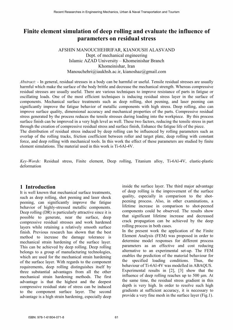
Fig. 3: The model of deep rolling
Table 4: The dimensions of the roller and work
piece shown in Fig. 3
Roller Workpiece
r 0. 9 mm a 6 mm
h 0.1 mm b 8 mm
V 10 m/s c 2 mm
d 4 mm
e 0.5 mm
5 Numerical results Five aspects of the deep rolling model are examined
in current work. The first is concerned with the
effect of overlap, the second is effect of friction
coefficient between the roller and target plate, the
third is deep rolling with constant force, the fourth is
deep rolling with mechanical tools, and the fifth is
deep rolling with vibration of workpiece.
All results obtained from variation of residual stress
along the path that is created by selecting nodes
along the central axis in target plate. The Path is
shown in Fig. 4.
The stress distributions in x, y and z directions,
indicated in Fig (5), are typically shown in Fig 6. As
the figure indicates, the stress component in Y-
direction (YYσ ) is not so significant and can be
considered negligible. However, the stress
component in x-direction (XXσ ), which coincides
with rolling direction is considerable but still is
significantly lower than the stress component in Z-
direction (ZZσ ), which is perpendicular to the
direction of rolling. However, only the stress
component XXσ is considered for evaluation of the
effects of the rolling parameters on residual stress
distribution, induced by deep rolling in this work.
Fig. 4: Path along Y-direction in target plate.
Fig.5 (a) Finite element model of the work piece (b)
a deep rolling model
Fig.6. The stress distribution in x, y and z directions
5.1 Effect of overlap The deep rolling finite element analysis is
performed to investigate the influence of overlap.
Six different overlaps are considered: 0, 8.3, 16.6,
25, 33 and 42%. In this analysis a rigid roller with
radius of R= 0.9 mm is used. The variation of
residual stress XXσ along the mention path for five
amount of overlap selected is shown in Fig. 7.
Furthermore, it shows that increased overlap results
in increased magnitude of the maximum residual
stress. But 42% overlap causing a surface
contraction and cause burr on the surface, so a
complete analysis is not possible.
Recent Researches in Engineering Mechanics, Urban & Naval Transportation and Tourism
ISBN: 978-1-61804-071-8 64
Page 5
Fig.7. Variation of overlap
5.2 Effect of coefficient friction The residual stress profile along the mentioned path
against the varied coefficient friction is plotted in
fig.8. The figure clearly shows that increase in the
coefficient of friction results in decrease magnitude
of the maximum residual stress and for coefficient
of friction µ ≥0.1 the effect of friction can cause
instability of the diagram. Increased coefficient of
friction between the contact workpieces and the
roller will cause contraction. To demonstrate this,
the Horizontal displacement of a point of the
workpiece surface in two cases frictionless and
f=0.5 have been compared. This can be observed
that moving perpendicular to the surface in the two
cases are almost identical. While moving in the
direction of rolling in frictionless case is less than
other cases.
Fig.8. Effect of coefficient friction
5.3 Deep rolling with constant force: The residual stress profile along the mentioned path
against the varied force is plotted in fig.9. As the
figure suggests, the increase of rolling force gives
rise to the increase of the residual stress up to a
specific value of rolling force, f =1400 kN. Further
increase in force rolling gives rise to reduction of
residual stress. Two substantial cases of diagram can
be seen. The first is that the residual stress at a depth
more than 0.5 mm for different value of force is
almost identical. This indicates that the deep rolling
process is a surface process and changes in the
parameters affect only on surface residual stress.
The second is that there is an error in the results at a
depth less than 0.1 mm because of the coarse mesh
in this area. However due to the high process time a
smaller mesh size is not possible. For this reason,
the depth, less than 0.1 in conclusion is not
considered.
Fig.9. Deep rolling with constant force on various forces
5.4 Deep rolling with mechanical tools In this case, the pressure required for deep rolling is
supplied by the spring force. The processed forces
are regulated by changing in the amount of spring
compression. Fig.10 shows the variation of residual
stress,XXσ , along the mention path for five
situation. Fig.10 shows that increase in the spring
compression results in largely increase magnitude of
the residual stress created in workpiece.
Also, this case compared with a constant force mode
as shown in Fig.11. To be able to compare two
charts with each other they need to be equal in their
forces. In the mechanical method by drawing roller
displacement chart versus the processes time we
observed that it has a little amplitude. Therefor we
can obtain spring force by multiplying initial
compresion to the spring cofficient. The fig.11
clearly shows the deep rolling with mechanical tools
was better than the constant force mode and
provides a higher residual stress. And the maximum
residual stress in more depth there.
Fig.10. Deep rolling with mechanical tools
Recent Researches in Engineering Mechanics, Urban & Naval Transportation and Tourism
ISBN: 978-1-61804-071-8 65
Page 6
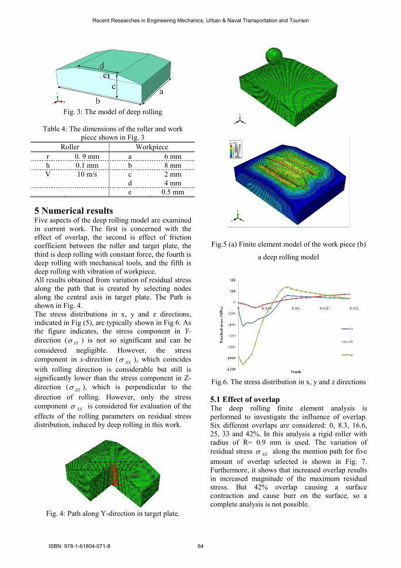
Fig.11. Comparision between two methods of force
constant and mechanical tools
5.5 Deep rolling with vibration of workpiece In this section deep rolling is done using the
hydrostatic tools and the vibrational with frequency
8 kHz is applied to workpiece. The vibration in xy
plane and along the x axis is applied. The result is
compared with deep rolling under the same
conditions and without vibration. The results are
shown in Fig 12.
Fig.12. Comparision between deep rolling with
vibration and normal method
The figure clearly shows that by using the vibrating
workpiece results in largely increase magnitude of
the residual stress created in workpiece and increase
depth of the compressed residual stress also increase
magnitude of the maximum residual stress.
This vibration by using constraint displacement and
as a periodic is defined and is defined by equation 3.
∑=
−+−+=N
n
nn ttnBttnAAa1
000 )](sin)(cos[ ωω
for t≥t0
(3)
Where A0 is the initial amplitude, t0 is starting time,
A and B are amplitude curve and ω is Circular
frequency. The material constants used in this
equation are resented in Table 5.
Table 5: Constants used in equation 3
A0 An Bn N ω t0
0 10-6
0 1 52360 0
This is equivalent with the state that the workpiece
is stationary and roller has an oscillating velocity.
Speed chart in the first step if the workpiece
stationary and feed rate oscillating is assumed and
normal mode which velocity is constant without
fluctuating is shown on Fig 13.
Fig 13: Compare speed in two modes, normal and
by using speed fluctuation
6 Conclusions A comprehensive 3D finite element dynamic
analysis with considering spring back effect was
conducted to simulate the deep rolling process. The
model was validated by comparison of the residual
stress profiles obtained by simulation and result X-
Ray diffraction technique that was proposed by [1].
The effect of overlap of the rolling tracks, friction
coefficient between roller and target plate, deep
rolling with constant force, deep rolling with
mechanical tools, and vibration of workpiece of
residual stress XXσ after spring back have been
examined and discussed.
The results revealed that increase in overlap of the
rolling tracks largely increases the magnitude of the
residual stress filed created in target plate.
Moreover, increase in the friction coefficient
between roller and target plate results in decreases
magnitude of the residual stress filed. For high
coefficient of friction the effect of friction can cause
instability of the diagram. However deep rolling is
done in two cases. The first case was constant force.
The results revealed that increase in the force
intensity results in increase magnitude of the
maximum residual stress. Latter was done using
mechanical tools. Results showed that increase in
the spring compression results in increase
Recent Researches in Engineering Mechanics, Urban & Naval Transportation and Tourism
ISBN: 978-1-61804-071-8 66
Page 7
magnitude of the residual stress created in
workpiece. Generally all graphs show the fact that
for the depth less than 0.1 mm, there is an error in
the results because of the coarse mesh in this area.
Therefore, this area has been ignored by analyzing.
As well as effect of workpiece vibration in the
direction of deep rolling was investigated and
observed that workpiece vibration results in increase
magnitude of the residual stress created in
workpiece and increase magnitude of the maximum
residual stress.
References
[1] Tsuji N, Tanaka S, Takasugi T, “Evaluation of
surface-modified Ti–6Al–4V alloy by combination
of plasma-carburizing and deep-rolling,” Materials
Science and Engineering A 488 (2008) 139–145
[2] Mader S, “Festwalzen von Fan- und
Verdichterschaufeln,” Dissertation (RWTH Aachen)
wt-online - Ausgabe 6-2008, S. 476-480.
[3] Klocke F, Bäcker V, Timmer A and Wegner H,
“Innovative FE-Analysis of the Roller Burnishing
Process for Different Geometries,” ed. E Oñate
(Barcelona: CIMNE) pp 1-4.
[4] Altenberger I, “Deep Rolling—The Past, the
Present and the Future,” Proceedings of 9th
International Conference on Shot Peening, Sept 6–9
(Paris, France), 2005, p 144–155
[5] Rajesh N, Veeraraghavan S, Ramesh Babu N,
“A novel approach for modelling of water jet
peening,” J. of Machine Tools & Manufacture, 44
(2004) 855.
[6] Altenberger I, Scholtes B, Martin U and Oettel
H, “Cyclic deformation and near surface
microstructures of shot peened or deep rolled
austenitic stainless steel AISI 304,” Materials
Science and Engineering A, 264 (1999) 1.
[7] Preve´y P.S and Cammett J, “Low Cost
Corrosion Damage Mitigation and Improved
Fatigue Performance of Low Plasticity Burnished,”
7075-T6, J. Mater. Eng. Perform., 2001, 10(5), p
548–555
[8] Daly J.J, Harrison J.R, and Hackel L.A, “New
Laser Technology Makes Laser Shot Peening
Commercially Affordable”, Proceedings of 7th
International Conference on Shot Peening, Sept 28–
30 (Warsaw, Poland), 1999, p 379–386
[9] Abramov V.O, Abramov O.V, Sommer F,
Gradov O.M, and Smirnov O.M, “Surface
Hardening of Metals by Ultrasonically Accelerated
Small Metal Balls,” Ultrasonics, 1998, 36(10), p
1013–1019
[10] Statnikov E.S, Muktepavel V.O et al.,
“Efficiency Evaluation of Ultrasonic Impact
Treatment (UIT) of Welded Joints in Weldox 420
Steel in Accordance with the IIW Program,”
APPLIED ULTRASONICS, IIW/IIS—DOCUMENT
XIII-1817-00,30 p.
[11] You-Li Zhu, Kan Wang, Li Li, and Yuan-Lin
Huang, ”Evaluation of an Ultrasound-Aided Deep
Rolling Process for Anti-Fatigue Applications”,
Journal of Materials Engineering and Performance,
November 2009, Volume 18(8) , p 1036–1040
[12] Altenberger I, Stach E.A, Liu G, Nalla R.K,
Ritchie R.O, An in situ transmission electron
microscope study of the thermal stability of near-
surface microstructures induced by deep rolling and
laser-shock peening, Scripta Materialia 48 (2003)
1593–1598
[13] Tolga Bozdana A, Nabil N.Z.Gindy, Hua Li,
Deep cold rolling with ultrasonic vibrations—a new
mechanical surface enhancement technique,
International Journal of Machine Tools &
Manufacture 45 (2005) 713–718
[14] Juijerm P and Altenberger I, Effect of high-
temperature deep rolling on cyclic deformation
behavior of solution-heat-treated Al–Mg–Si–Cu
alloy, Scripta Materialia 56 (2007) 285–288
[15] Tsuji N, Tanaka S, Takasugi T, Evaluation of
surface-modified Ti–6Al–4V alloy by combination
of plasma-carburizing and deep-rolling, Materials
Science and Engineering A 488 (2008) 139–145
[16] Bäcker V, Klocke F, Wegner H, Timmer A,
Grzhibovskis R, Rjasanow S, Analysis of the Deep
Rolling Process on Turbine Blades using the
FEM/BEM-Coupling, Materials Science and
Engineering 10 (2010) 012134
Recent Researches in Engineering Mechanics, Urban & Naval Transportation and Tourism
ISBN: 978-1-61804-071-8 67


![Detecting faulty rolling-element bearings faulty rolling-element bearings f Faulty rolling-elemen ] t bear- ... such fault iss to regularly mea sure the overall vibration level at](https://static.documents.pub/doc/80x56/5b028d597f8b9a65618f638a/detecting-faulty-rolling-element-bearings-faulty-rolling-element-bearings-f-faulty.jpg)

