34
1 Finite Impulse Response (FIR) Digital Filters (II) Ideal Impulse Response Design Examples Yogananda Isukapalli
1
Finite Impulse Response (FIR)
Digital Filters (II)
Ideal Impulse Response Design Examples
Yogananda Isukapalli
2
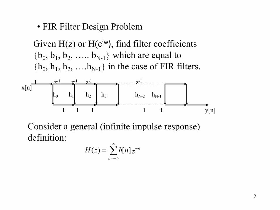
• FIR Filter Design Problem
y[n]
1 z-1 z-1 z-1 z-1
h0 h1 h2 h3 hN-2 hN-1
x[n]
1 1 1 1 1
Consider a general (infinite impulse response) definition:
å¥
-¥=
-=n
nznhzH ][)(
Given H(z) or H(ejw), find filter coefficients{b0, b1, b2, ….. bN-1} which are equal to {h0, h1, h2, ….hN-1} in the case of FIR filters.

3
Where C is a counterclockwise closed contour in the region of convergence of H(z) and encircling the origin of the z-plane
å¥
-¥=
-=n
jnwjw enheH ][)(
From complex variable theory, the inverse transform is:
ò -= C dznzzHj
nh 1)(21][p
• Evaluating H(z) on the unit circle ( z = ejw ) :
dweeHnh jnwjw)(21][ ò
-
=p
pp where dz = jejw dw
4
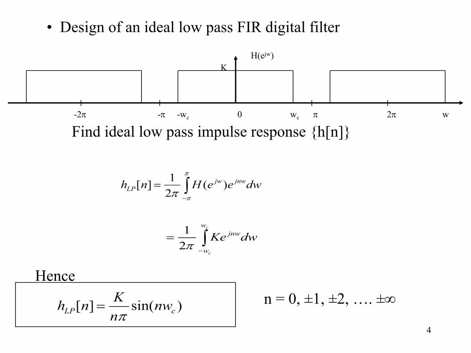
• Design of an ideal low pass FIR digital filter
-2p -p -wc 0 wc p 2p w
H(ejw)K
Find ideal low pass impulse response {h[n]}
ò-
=p
ppdweeHnh jnwjw
LP )(21][
ò-
=c
c
w
w
jnwdwKep21
Hence
)sin(][ cLP nwnKnhp
= n = 0, ±1, ±2, …. ±¥

5
Let K = 1, wc = p/4, n = 0, ±1, …, ±10
The impulse response coefficients are
n = ±4, h[n] = 0= ±5, = -0.043= ±6, = -0.053= ±7, = -0.032
n = 0, h[n] = 0.25= ±1, = 0.225= ±2, = 0.159= ±3, = 0.075
n = ±8, h[n] = 0= ±9, = 0.025= ±10, = 0.032

6
Non CausalFIR ImpulseResponse
We can make it causal if we shift hLP[n] by 10 units to the right:
))10sin(()10(
][ cLP wnnKnh --
=p n = 0, 1, 2, …. 20
7
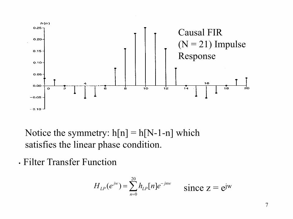
Causal FIR(N = 21) ImpulseResponse
Notice the symmetry: h[n] = h[N-1-n] whichsatisfies the linear phase condition.
• Filter Transfer Function
å=
-=20
0][)(
n
jnwLP
jwLP enheH since z = ejw
8
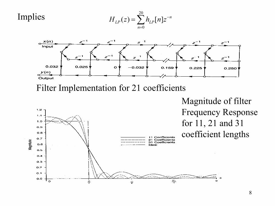
Implies å=
-=20
0][)(
n
nLPLP znhzH
Filter Implementation for 21 coefficientsMagnitude of filter Frequency Responsefor 11, 21 and 31coefficient lengths
9
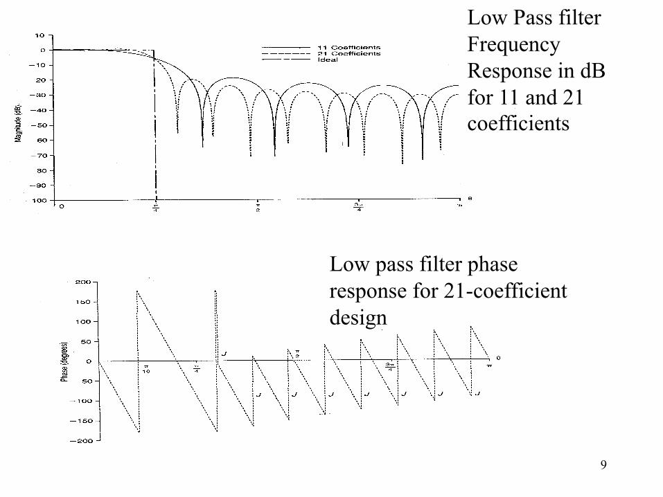
Low Pass filterFrequency Response in dBfor 11 and 21 coefficients
Low pass filter phaseresponse for 21-coefficientdesign

10
The above figure implies
)()( )( p-= wjLP
jwHP eHeH
nLPHP nhnh )1]([][ -=

11
Now:
å¥
-¥=
--=n
wjnLP
jwHP enheH )(][)( p å
¥
-¥=
- -=n
njnwLP enh )1(][
å¥
-¥=
--=n
jnwnLP enh )1]([
][nhHP
Example: Analog high pass filter specification
0 10 kHz f
Ideal high pass
Given: fs = 50kHz, it follows:w = WT= 2pf/fs = 0.4p rad
Digital specification: 0.4p = p - wa

12
\ wc (LPF) = p - wa = p - 0.4p = 0.6p
First design ideal LPF with wc= 0.6pAnswer : )6.0sin(1][ n
nnhLP p
p=
n = 0, ±1, ±2, …. ±¥Follows now:
nLPHP nhnh )1]([][ -=
))(6.0sin()(
)1(][ InIn
nhIn
HP --
-=
-
pp
The I indicates the length of the filter
Hence the above filter is a causal FIR high pass digital filter

13

14

15

16
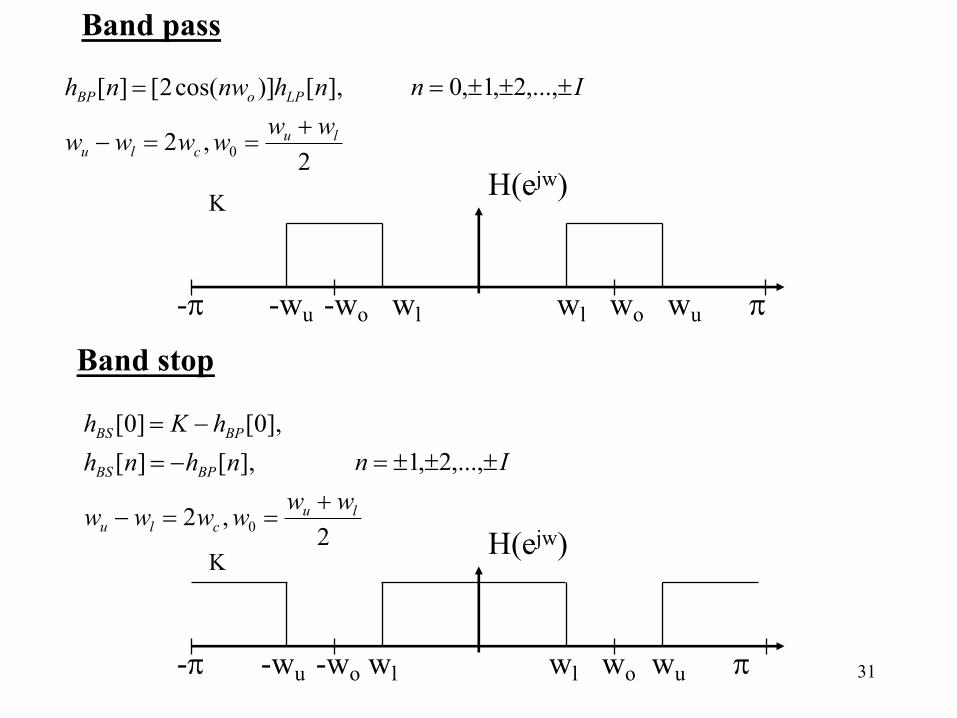
Bandpass FIR filter design:
-p -wu -wo-wl 0 wl wo wu p w
H(ejw)K
Shift to right: H(ejw) ejwo
Shift to left: H(ejw) e-jwo
Follows:][]cos2[][ nhnwnh LPoBP =
n = 0, ±1, ±2, …. ±Iwhere
)(2 lowpasswww clu =-
2lu
owww +
=

17
Example:
-15 -10 0 10 15 f in kHz
H(ejW)1 fs = 50kHz
Digital specifications:pp 4.0
)10)(5()10(24
4
==lw
pp 6.0)10)(5()5.1)(10(2
4
4
==uw
p5.0=ow
p1.02
=-
= luc
www

18
First design LPF:
)1.0sin(1][ nn
nhLP pp
= n = 0, ±1, ±2, ….
Follows: ][)5.0cos(2[][ nhnnh LPBP p= n = 0, ±1, ±2, ….

19
20
21
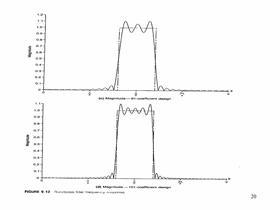
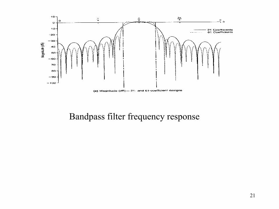
Bandpass filter frequency response
22
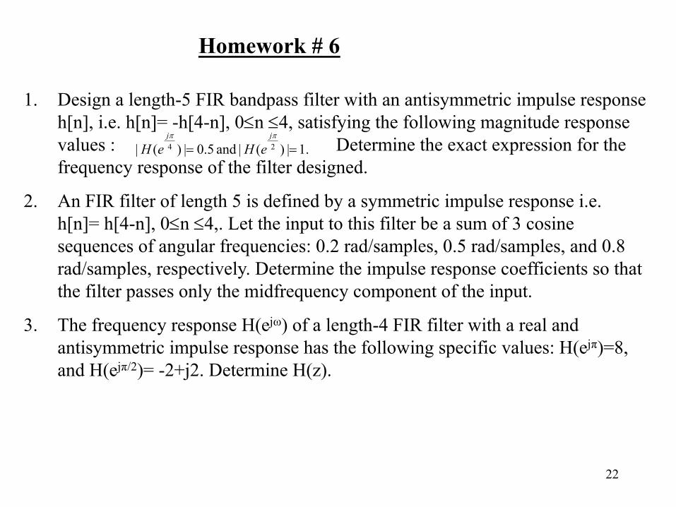
Homework # 6
1. Design a length-5 FIR bandpass filter with an antisymmetric impulse response h[n], i.e. h[n]= -h[4-n], 0£n £4, satisfying the following magnitude response values : Determine the exact expression for the frequency response of the filter designed.
2. An FIR filter of length 5 is defined by a symmetric impulse response i.e. h[n]= h[4-n], 0£n £4,. Let the input to this filter be a sum of 3 cosine sequences of angular frequencies: 0.2 rad/samples, 0.5 rad/samples, and 0.8 rad/samples, respectively. Determine the impulse response coefficients so that the filter passes only the midfrequency component of the input.
3. The frequency response H(ejω) of a length-4 FIR filter with a real and antisymmetric impulse response has the following specific values: H(ejπ)=8, and H(ejπ/2)= -2+j2. Determine H(z).
.1|)(| and 5.0|)(| 24 ==pp jj
eHeH

23
HLP(ejw)
-2p-wc -p -wc wc p 2p-wc w
Frequency transformations of ideal filters.
The ideal low filter frequency response is shown below. hLP[n]represents the non-causal impulse response of HLP(ejw)
0-2p 2p
HLP(ej(w-p))
-p-wc -p -p+wc p-wc p p+wc w0-2p 2p
Shifting the low pass filter frequency by p, we get
High pass Filter
24
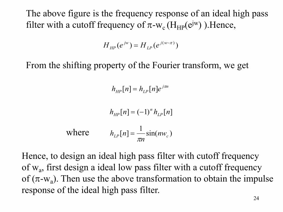
The above figure is the frequency response of an ideal high pass filter with a cutoff frequency of p-wc (HHP(ejw) ).Hence,
)()( )( p-= wjLP
jwHP eHeH
From the shifting property of the Fourier transform, we get
njLPHP enhnh p][][ =
][)1(][ nhnh LPn
HP -=
Hence, to design an ideal high pass filter with cutoff frequencyof wa, first design a ideal low pass filter with a cutoff frequencyof (p-wa). Then use the above transformation to obtain the impulseresponse of the ideal high pass filter.
)sin(1][ cLP nwn
nhp
=where

25
KHBP(ejw)
-p -wu -wo wl wl wo wu p
The frequency response for an ideal band pass filter is shown below. The center frequency is wo.
Looking at the frequency responses of a band pass filter and a lowpass filter, we can observe that a band pass filter is obtained byshifting the low pass filter to the left and to the right by wo andadding the two shifted responses.
HLP(ejw)
-p -wc wc p w
Low pass frequency response
Band pass Filter
26
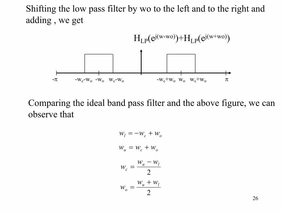
HLP(ej(w-wo))+HLP(ej(w+wo))
-p -wc-wo -wo wc-wo -wc+wo wo wc+wo p
Shifting the low pass filter by wo to the left and to the right and adding , we get
Comparing the ideal band pass filter and the above figure, we canobserve that
ocl www +-=
ocu www +=
2lu
cwww -
=
2lu
o
www
+=

27
The frequency response of the band pass filter HBP(ejw) is
)()()( )()( oo wwjLP
wwjLP
jwBP eHeHeH +- +=
From the shifting property of the Fourier transform , we have
njwLP
njwLPBP
oo enhenhnh -+= ][][][
)}cos(2]{[][
}]{[][
oLPBP
njwnjwLPBP
nwnhnh
eenhnh oo
=
+= -
To design a band pass filter, first design a low pass filter with cutoff frequency wc given by
2lu
cwww -
=
And use the above transformation to get the impulse response ofthe band pass filter .

28
Band stop Filter
HBS(ejw)
-wu -wo -wl wl wo wu w0-p p
The frequency response of an ideal band stop filter (HBS(ejw))is
Looking at the frequency responses of band stop and bandpass filters, we observe that the band stop filter is obtainedby subtracting the band pass from 1.
)(1)( jwBP
jwBS eHeH -=

29
åå¥
-¥=
-¥
-¥=
- -=n
jnwBP
n
jnwBS enhenh ][1][
If we work out the first few terms, we get
wjBP
jwBPBP
jwBP
wjBP
wjBS
jwBSBS
jwBS
wjBS
ehehhehehehehheheh
22
22
]2[]1[]0[1]1[]2[......
]2[]1[]0[]1[]2[......--
--
++-+-+-+=
+++-+-+
Hence, the impulse response coefficients for a band stop filter areobtained as
]0[21]0[1]0[ LPBPBS hhh -=-=
0 }cos(2]{[][][ ¹-=-= nnwnhnhnh oLPBPBS
30
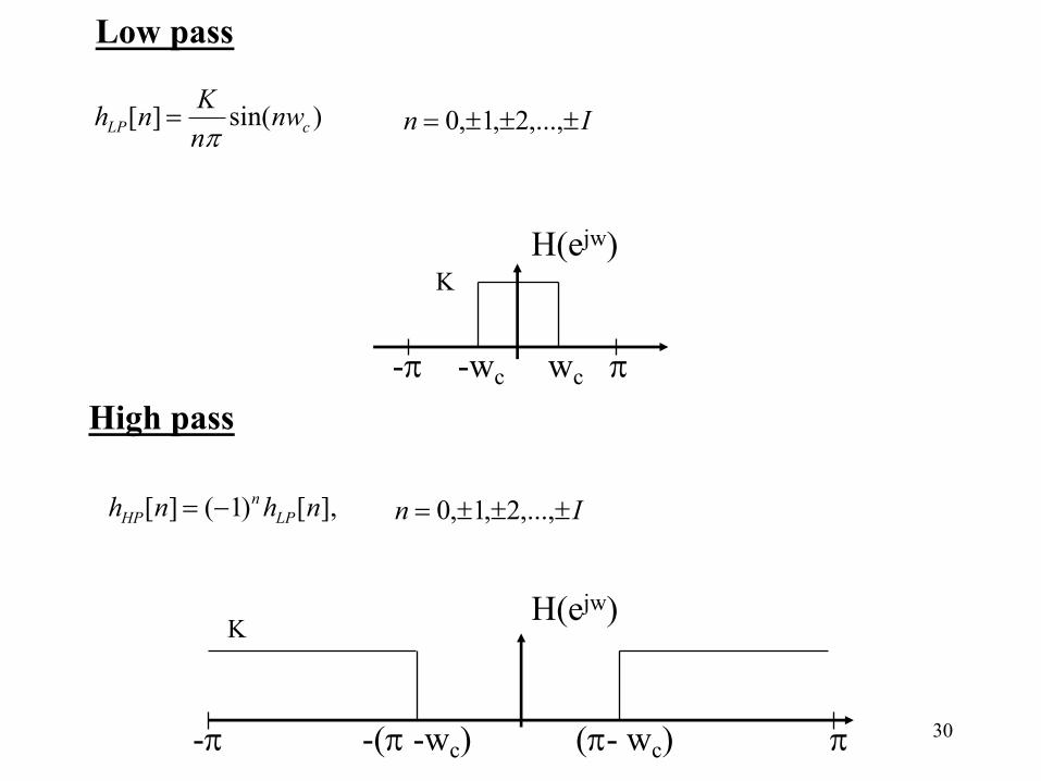
Low pass
)sin(][ cLP nwnKnhp
= In ±±±= ,...,2,1,0
H(ejw)K
-p -wc wc pHigh pass
],[)1(][ nhnh LPn
HP -= In ±±±= ,...,2,1,0
K
-p -(p -wc) (p- wc) p
H(ejw)
31
2,2
],[)]cos(2[][
0lu
clu
LPoBP
wwwwww
nhnwnh+
==-
= In ±±±= ,...,2,1,0
K
-p -wu -wo wl wl wo wu p
H(ejw)
Band pass
2,2
],[][],0[]0[
0lu
clu
BPBS
BPBS
wwwwww
nhnhhKh
+==-
-=-=
In ±±±= ,...,2,1
K
-p -wu -wo wl wl wo wu p
H(ejw)
Band stop
32
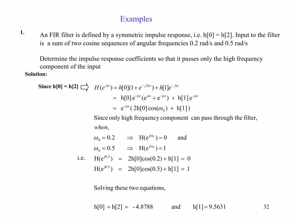
Examples1. An FIR filter is defined by a symmetric impulse response, i.e. h[0] = h[2]. Input to the filter
is a sum of two cosine sequences of angular frequencies 0.2 rad/s and 0.5 rad/s
Determine the impulse response coefficients so that it passes only the high frequency component of the input
Solution:
Since h[0] = h[2]
9.5631 h[1] and 4.8788- h[2] h[0]
equations, two theseSolving
1 h[1] .5)2h[0]cos(0 )H(e
0 h[1] .2)2h[0]cos(0 )H(e
1)H(e 5.0
and 0)H(e 2.0
,filter, he through tpasscan component frequency high only Since
) h[1] )cos( 2h[0] (e
e h[1] )e(ee h[0]
]1[)1](0[)(
j0.5
j0.2
j0
j0
0j-
j-j-jj-
2
0
0
===
=+=
=+=
=Þ=
=Þ=
+=
++=
++= --
w
w
w
wwww
www
w
w
w
when
eheheH jjj
i.e.
33
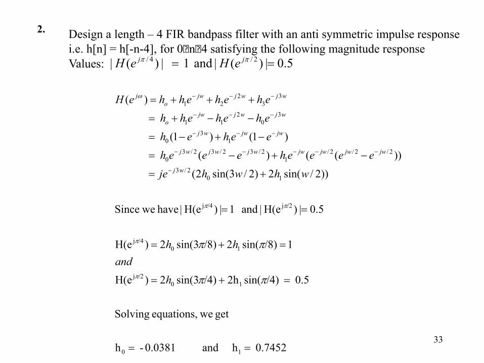
2. Design a length – 4 FIR bandpass filter with an anti symmetric impulse responsei.e. h[n] = h[-n-4], for 0�n�4 satisfying the following magnitude responseValues: 5.0|)(| and 1 |)(| 2/4/ == pp jj eHeH
0.7452 h and 0.0381- h
get weequations, Solving
0.5 /4)sin(2h /4)3sin(2)H(e
1/8)sin(2/8)3sin(2)H(e
5.0|)H(e| and 1|)H(e| have weSince
))2/sin(2)2/3sin(2(
))(()(
)1()1(
)(
10
10/2j
10/4j
/2j/4j
102/3
2/2/2/1
2/32/32/30
13
0
30
211
33
221
==
=+=
=+=
==
+=
-+-=
-+-=
--+=
+++=
-
-----
---
---
---
pp
pp
p
p
pp
w
h
andhh
whwhje
eeeeheeeh
eeheh
ehehehh
ehehehheH
wj
jwjwjwjwwjwjwj
jwjwwj
wjwjjwo
wjwjjwo
j

34
3. The frequency response of a length-4 FIR filter has values:
0|)(| and 37|)(| 2|)(| 2/0 =-== pp jjj eHjeHeHDetermine H(z)
Solution
Using the symmetry property of DTFT of a real sequence, we observe that
37|)(*||)(| 2/2/3 jeHeH jj +== pp
Thus the 4 point DFT of the sequence is given by:
]37, 0 ,37, 2[)( jjkH +-=
The inverse DFT of the H(k) gives h(n) as:
h(n) = (4 , 2 , -3 , -1) (using ifft in MATLAB)
Therefore H(z) is:
32-1 32z 4 )( -- --+= zzzH


