1 Finite wings Infinite wing (2d) versus finite wing (3d) – Definition of aspect ratio: – Symbol changes: 2 b b AR AR S c ≡ = l L d D m M C C C C C C → → → For rectangular platform Vortices and wings What the third dimension does – Difference between upper and lower pressure results in circulatory motion about the wingtips – Vortices develop – Causing downwash – Drag is increased by this induced downwash LOWER PRESSURE HIGHER PRESSURE VORTEX VORTEX ∞ V ∞ V w ∞ V WINGTIP VORTEX CAUSES DOWNWASH, w LOCAL FLOW
Transcript
1
Finite wings
� Infinite wing (2d) versus finite wing (3d)
– Definition of aspect ratio:
– Symbol changes:
2b bAR AR
S c≡ � =
l L d D m MC C C C C C→ → →
For rectangular platform
Vortices and wings
� What the third dimension does– Difference between upper and lower pressure results in
circulatory motion about the wingtips
– Vortices develop
– Causing downwash
– Drag is increased by this induced downwash
LOWER PRESSURE
HIGHER PRESSURE
VORTEXVORTEX
∞V
∞Vw
∞V WINGTIP VORTEXCAUSES DOWNWASH, w
LOCAL FLOW
2
Origin of induced drag
� Wingtip vortices alter flow field – Resulting pressure distribution increases drag – Rotational kinetic energy is added to the 2-D flow– Lift vector is tilted back
� AOA is effectively reduced� Component of force in drag direction is generated
Induced drag
– The sketch shows– For small angles of attack– The value of αi for a given section of a finite wing depends on the
distribution of downwash along the span of the wing
ii sinLD α=
iisin α≈α
3
� Lift per unit span varies– Chord may vary in length along the wing span– Twist may be added so that each airfoil section is
at a different geometric angle of attack– The shape of the airfoil section may change along
the wing span Lift per unit span as a function of distancealong the span -- also called the lift distribution
The downwash distribution, w, which results from the lift distribution
b
Lift per unit span
� An elliptical lift distribution
– Produces a uniform downwash distribution– For a uniform downwash distribution, incompressible theory
predicts that
� Where is the finite wing (3d) lift coefficient
Aspect Ratio
b
ARCL
i π=α
LC
Sb
AR2
=
Elliptical lift distribution
4
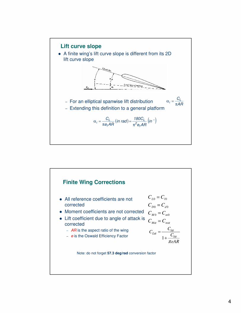
Lift curve slope� A finite wing’s lift curve slope is different from its 2D
lift curve slope
– For an elliptical spanwise lift distribution– Extending this definition to a general platform
ARCL
i π=α
( ) ( )�inAReC180
radinARe
C
12
L
1
Li π
=π
=α
Finite Wing Corrections
� All reference coefficients are not corrected
� Moment coefficients are not corrected� Lift coefficient due to angle of attack is
corrected– AR is the aspect ratio of the wing– e is the Oswald Efficiency Factor
αα mM
mM
dD
lL
CC
CC
CC
CC
====
00
00
00
1
lL
l
CC
CeAR
αα
απ
=+
Note: do not forget 57.3 deg/rad conversion factor
5
0
01
aa
aeARπ
=+
Finite Wing Corrections – High Aspect Ratio Wings (lifting line theory)