15
Fire alarm and extinguishing systems _ General Catalogue

Fire alarm and extinguishingsystems _ General Catalogue

Fire.
The menace advances. What’s the next move?
Play safe. Choose FeelSef.
Space protected. Danger eliminated.
Everything under control.
GAME OVER
4
Delivering excellence in security means being ahead of time.
FeelSef innovates! FeelSef designs advanced, fl exible technologies with an easy
edge that installer companies and end users will appreciate.
From design to production, from testing to marketing, quality is our referance
line.,
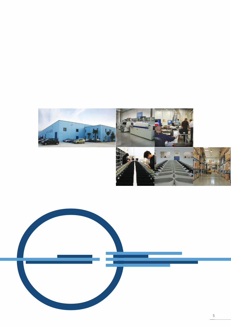
FeelSef product is made in Italy.
A team with over 20 years of experience yet only one desire: your security.
Made in FeelSef. Made in Italy.
5
Emergency54
When an FeelSef system is combined with “Emergency54” technology, it is without
doubt the maximum level of reliability installer companies can expect to fi nd in a fi re-
detection system.
An “Emergency54” enhanced system is capable of activating fi re alarm signaling even
under the improbable conditions of a control panel CPU fault.
Emergency54 technology operates at panel level – to ensure signaling during a control
panel CPU fault; and at network level – to ensure signaling during a main unit CPU fault.
The Emergency54 also extends its functions to telephone communications. In fact, if
the system is equipped with a SafeLoopPSTN board, it guarantees an emergency call in
the event of an alarm during control panel CPU fault conditions.
The “Emergency54” enhancement technology is for those installer companies who
wish to shape systems without compromise.
HorNet
The “HorNet” token-ring network is the ultimate in embedded RS485 supported systems.
The highly fault-tolerant “HorNet” architecture is able to reconfi gure itself in such a way as
to protect the ring connectivity in the event of a network fault.
The real-time information exchange between control panels allows the system to activate
the devices of one control panel in immediate response to an event on another. The
HorNet” token-ring ensures that all the panels in the confi guration are totally aware of
“what-is-going-on” in the complete system of up to 30 control panels.
Janus
Janus technology is truly astounding. This technology is embedded in SafeLAN board.
By accessorizing the control panel with a SafeLAN board, users will be allowed
“no-risk” worldwide access to the system via Internet.
If the SafeLAN enhanced control panel is part of a HorNet token-ring, users will be able
to interact with all the panels in the confi guration, using the SafeLAN as the system
gateway.
As well as providing easy remote access, the SafeLAN also off ers the opportunity to
send e-mail and UDP and TCP/IP data packets for system enquiry and programming
purposes.
FeelSef is continuously active in the search for forward thinking solutions to the everyday challenges faced by installer companies.
In pursuance of this quest, FeelSef’s R & D professionals are always looking to push the known boundaries of technology toward a
totally new class of products with unmatched capabilities.
Every FeelSef device is designed to take full advantage of state-of-the-art microcontroller technology, network architecture and
communication infrastructures. The following pages allow you to take a glimpse at the technologies developed at FeelSef’s
laboratories and catch sight of the future of fi re detection, today.
Technologies
Centrali
6
Versa++
FeelSef has launched a whole new concept into the world of conventional detection:
fl exibility.
In fact, as a result of the revolutionary Versa++ technology incorporated in the IRIS and
ENEA detector ranges, you can now confi gure individual detectors to suit their specifi c
environments. You can also connect to the detector line for a complete diagnosis of
each individual detector and thus test its operating capacity, verify real-time values,
view the contamination level in the optical smoke chamber and change the sensitivity
and operating mode. Each detector has a non-volatile memory which allows you to
view the smoke and temperature levels measured in the period prior to the last alarm
detected. Versa++ gives you the true feel of the future of fi re detection.
LoopMap
LoopMap technology is so new that it seems to have come out of the latest video-
game. It is the apex of loop technology. Once the loop is connected to the control
panel or loop pilot, you simply start the enrolling process via your computer to obtain
the loop layout containing all details and any secondary branches, in the order in which
the wiring was completed. LoopMap is capable of recognizing the wiring order of the
loop devices even when the loop has branches.
LoopMap technology allows you to reconstruct the exact installation topology and
obtain an easy-to-use, interactive loop-layout map which greatly simplifi es and speeds
up searches relating to faults and maintenance work.
OpenLoop
OpenLoop technology is the outcome of the concerted eff orts of the R & D professionals
at FeelSef Electronics. This breakthrough technology allows FeelSef panels to accomodate
diff erent brands of peripheral devices by design. This is the most high-tech approach to
device management available on the fi re security market to date. The loop is in fact “open”
and ready-to-run diff erent brands of peripheral devices. It also supports all types of fi re
system devices (detectors, input modules, output modules, callpoints, sirens, etc.). The
loops can be 2 or 4 wire confi gured (maximum wire length 2000m). FeelSef’s OpenLoop
technology also provides impressive self-diagnostic functions for loop anomaly detection.
The outstanding management capacity of each loop allows the panel to manage an
impressive 240 devices.
The consistent performance and reliability of this advanced technology in “critical” high-noise
conditions highlights its potential even more. Designed with the intent to go beyond the
requirements of the related Directive standards, the loop and the entire spectrum of FeelSef’s
Fire alarm and extinguishingsystems _ General Catalogue
7

SafeLineConventional control panels with 2 zones or 4 zones expandable to 36
The SafeLine conventional fi re-detection control panel series off ers a 2 zone non-expandable model (SafeLine020-2), a 4 zone
model expandable to 20 zones (SafeLine020-4) and a 4 zone model expandable to 36 zones (SafeLine036).
The extreme compactness, trouble-free installation, uncomplicated programming procedures and simple end-user operation
make this highly competitive control panel ideal for all small and medium applications, especially those applications where fast
installation and programming are among the most important aspects of the system. The numerous functions (timers, equational
logic, etc.), extensive fl exibility (automatic output balancing, multifunction inputs, customizable outputs, gas function integration,
etc.), and innovative connectivity capabilities (RS485 BUS for power supply stations, Internet connection, etc.), provide the
tranquillity of knowing for sure that this powerful tool is capable of satisfying every need of every type of installation.
SafeLine control panels have supervised outputs (one on the motherboard and one on each added expansion) for the activation
of audio-visual signalling devices, a customizable relay output, fault signaling outputs and two 24V outputs (one constant and one
interruptible by installer-defi ned conditions). Additionally, each detection zone provides a terminal which can be confi gured as:
open-collector output (activated by programmable conditions), supervised input, or Gas 4-20mA detector interface.
System information is provided through the graphic display and LEDs on the control panel frontplate. The RS485 BUS supports 4
remote repeater panels (SafeLetUSee/LCD-Lite). These repeater panels replicate all the fi re alarm system data and allow users to
access and control the system in accordance with their authorized access level. The BUS also supports two power-supply stations
which can be connected in such a way as to allow supervision of their functionality and activation/deactivation of their output
power during predefi ned conditions. Programming the system from the control panel is straightforward and trouble-free thanks
to the easy-to-follow instructions on the display. The system can also be programmed by means of the SafeLeague software
application. This intuitive programming software greatly simplifi es the programming procedure. The SafeLAN/485 board allows
the control panel to connect to an Ethernet network for remote access via the Internet. Once the remote connection has been
established, it is possible to modify the confi guration parameters, upload/download programming data and/or manage the system
by means of the supervisory software based on SafeLook graphic maps.
EN 54-2EN 54-4EN 12094-1
8
SafeLineconventional control panels

SafeLetUSee/LCD-Lite
Remote repeater panel with display and keypad for user operations.
SafeLAN/485
Ethernet connection board. Allows the control panel to connect to an Ethernet network for remote for programming and monitoring via the Internet using SafeLook graphic maps.
SafeLine/8Z
8 zone expansion board equipped with an additional supervised output.
SafeLetLoose/ONE
Fire extinction board. Provides the system with GAS extinguisher control capabilities. Approved CPD - EN12094-1.
SafeLevel
Power supply station connectable to the RS485 BUS (for supervision and management of the control panel power outputs). Refer to “Power supply stations”.
Accessory items
Features and Technical specifi cations
• Conventional fi re-detection control panel.• Available with 2 zones, 4 zones expandable to 20, 4 zones expandable to 36• Certifi ed EN54 / EN54-2• Certifi ed EN12094-1 (Fire extinction)• Supports up to 32 devices per zone• Manages SafeLetLoose/ONE Fire Extinction board (Function EN12094-1 Approved)• 1 supervised alarm output (NAC)• 1 output for communicator/dialler activation• 1 dry-contact alarm output• 1 dry-contact fault output• 1 ancillary power supply output• 1 interruptible power supply output• 1 additional terminal per zone confi gurable as: open-collector output, supervised input, Gas detector input with 4-20mA interface• Battery shutdown relay for deep discharge conditions• Backlit graphic display for easy management of Installer/User interface• Navigation keys for easy access to graphic display functions• Fast keys (Silence, Reset, Evacuate, Investigate)• RS485 BUS for the connection of Repeater panels and Power supply stations (SafeLevel)• Buzzer (provides audible signals)• 8 Timers• 8 logical equations• Automatic balancing of individual detector lines• RS232 connector for system programming from a PC • Programming software• Easy system programming from the control panel• Access key for Level 2 functions (EN54 compliant)• Thermal probe for battery optimization• Battery effi ciency test• Extensive application of SMD refl ux technology for higher reliability• Metal enclosure• Mains power supply 230Vac• Switching power supply/battery charger 1.4A @ 27.6Vdc (for SafeLine020) or 4A @ 27.6Vdc (for SafeLine036)• Battery housing for two 7Ah - 12V batteries (for SafeLine020) or two 17Ah - 12V batteries (for SafeLine036)• Dimensions (HxWxD for SafeLine020): 325x325x80mm - (HxWxD for SafeLine036): 497x380x87mm• Weight (without batteries): SafeLine020 = 3Kg; SafeLine036 = 6Kg
Fire alarm and extinguishingsystems _ General Catalogue
9
Main Features
• Certifi ed EN12094-1• Microcontroller board supervised by the CPU• Indicator LEDs (status, disabled, faults)• Supervised terminals for manual fi re extinction commands• Supervised terminals for STOP fi re extinction commands• Supervised terminals for pressure switch control• Supervised output for fi re suppression system activation• Supervised output for signaling activation (pre-extinguish)• Supervised output for “Gas in area” signaling
ORDER CODES
SafeLine020-2: non-expandable 2 zone conventional control panel
SafeLine020-4: conventional control panel with 4 zones expandable to 20
SafeLine036: conventional control panel with 4 zones expandable to 36
SafeLine/8Z: 8 zone expansion board
SafeLAN/485: ethernet connection board
SafeLetLoose/ONE: fi re suppression board
SafeLetUSee/LCD-Lite: remote-control repeater panel for SafeLine and SafeLight control panels
SafeLeague: programming and management software
Link232F9F9: RS232 cable link between PC and FeelSef devices
IPS24040: switching power supply/battery charger [email protected]
IPS24140: switching power supply/battery charger [email protected]
ProbeTH: thermal probe for optimized battery charge
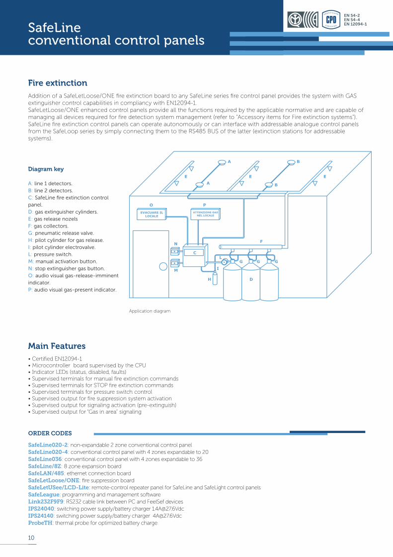
Fire extinction
Addition of a SafeLetLoose/ONE fi re extinction board to any SafeLine series fi re control panel provides the system with GAS extinguisher control capabilities in compliancy with EN12094-1.SafeLetLoose/ONE enhanced control panels provide all the functions required by the applicable normative and are capable of managing all devices required for fi re detection system management (refer to “Accessory items for Fire extinction systems”). SafeLine fi re extinction control panels can operate autonomously or can interface with addressable analogue control panels from the SafeLoop series by simply connecting them to the RS485 BUS of the latter (extinction stations for addressable systems).
Application diagram
Diagram key
A: line 1 detectors.B: line 2 detectors.C: SafeLine fi re extinction control panel.D: gas extinguisher cylinders.E: gas release nozelsF: gas collectors.G: pneumatic release valve.H: pilot cylinder for gas release.I: pilot cylinder electrovalve.L: pressure switch.M: manual activation button.N: stop extinguisher gas button.O: audio visual gas-release-imminent indicator.P: audio visual gas-present indicator.
10
EN 54-2EN 54-4EN 12094-1SafeLine
conventional control panels
Parameter ID100 ID200 ID300
Operating voltage 10-30 Vdc
Consumption during standby 90 uA 70 uA 90 uA
Consumption during alarm Max 40 mA
Sensitivity 0.08 – 0.10 – 0.12 – 0.15 dB/mA1R (58°C + RoR) – B (72°C) – BR(72°C + RoR) – A2S (58°C)
0.08 – 0.10 – 0.12 – 0.15 dB/m-------------------------------------A1R (58°C + RoR) – B (72°C) – BR(72°C + RoR) – A2S (58°C)
-----------------------------------------Modalità AND – OR - PLUS
Operating temperature -5°C + 40°C
Height including base 46mm 54mm
Diameter 110mm
Weight (with base) 160g
Weight (without base) 90g
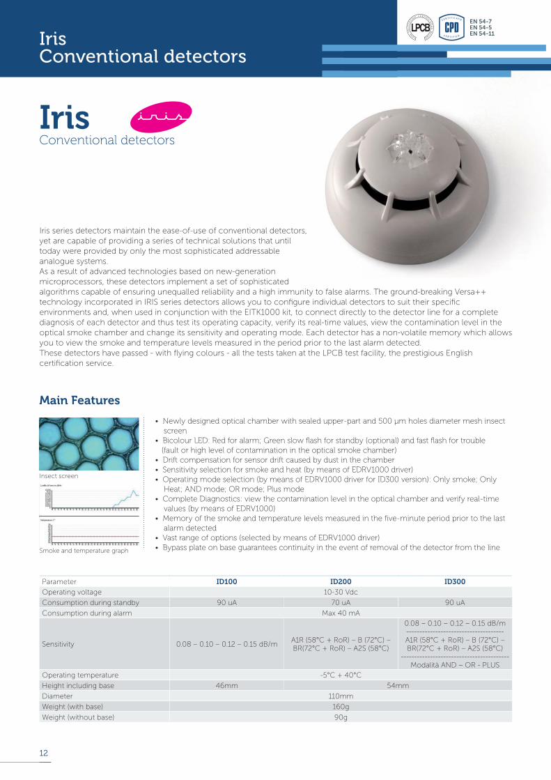
• Newly designed optical chamber with sealed upper-part and 500 μm holes diameter mesh insect screen• Bicolour LED: Red for alarm; Green slow fl ash for standby (optional) and fast fl ash for trouble (fault or high level of contamination in the optical smoke chamber)• Drift compensation for sensor drift caused by dust in the chamber• Sensitivity selection for smoke and heat (by means of EDRV1000 driver)• Operating mode selection (by means of EDRV1000 driver for ID300 version): Only smoke; Only Heat; AND mode; OR mode; Plus mode• Complete Diagnostics: view the contamination level in the optical chamber and verify real-time values (by means of EDRV1000)• Memory of the smoke and temperature levels measured in the fi ve-minute period prior to the last alarm detected• Vast range of options (selected by means of EDRV1000 driver)• Bypass plate on base guarantees continuity in the event of removal of the detector from the line
IrisConventional detectors
Main Features
Iris series detectors maintain the ease-of-use of conventional detectors,
yet are capable of providing a series of technical solutions that until
today were provided by only the most sophisticated addressable
analogue systems.
As a result of advanced technologies based on new-generation
microprocessors, these detectors implement a set of sophisticated
algorithms capable of ensuring unequalled reliability and a high immunity to false alarms. The ground-breaking Versa++
technology incorporated in IRIS series detectors allows you to confi gure individual detectors to suit their specifi c
environments and, when used in conjunction with the EITK1000 kit, to connect directly to the detector line for a complete
diagnosis of each detector and thus test its operating capacity, verify its real-time values, view the contamination level in the
optical smoke chamber and change its sensitivity and operating mode. Each detector has a non-volatile memory which allows
you to view the smoke and temperature levels measured in the period prior to the last alarm detected.
These detectors have passed - with fl ying colours - all the tests taken at the LPCB test facility, the prestigious English
certifi cation service.
Insect screen
Smoke and temperature graph
12
Iris Conventional detectors
EN 54-7EN 54-5EN 54-11
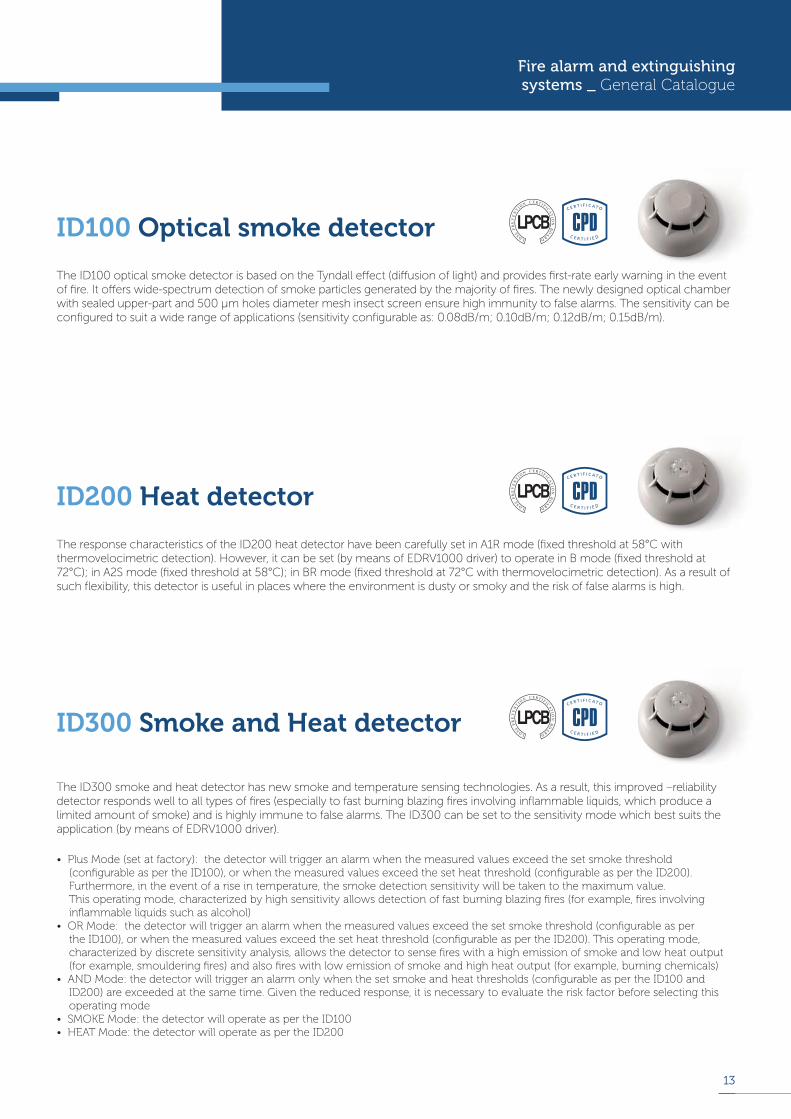
The ID100 optical smoke detector is based on the Tyndall eff ect (diff usion of light) and provides fi rst-rate early warning in the event of fi re. It off ers wide-spectrum detection of smoke particles generated by the majority of fi res. The newly designed optical chamber with sealed upper-part and 500 μm holes diameter mesh insect screen ensure high immunity to false alarms. The sensitivity can be confi gured to suit a wide range of applications (sensitivity confi gurable as: 0.08dB/m; 0.10dB/m; 0.12dB/m; 0.15dB/m).
ID100 Optical smoke detector
• Plus Mode (set at factory): the detector will trigger an alarm when the measured values exceed the set smoke threshold (confi gurable as per the ID100), or when the measured values exceed the set heat threshold (confi gurable as per the ID200). Furthermore, in the event of a rise in temperature, the smoke detection sensitivity will be taken to the maximum value. This operating mode, characterized by high sensitivity allows detection of fast burning blazing fi res (for example, fi res involving infl ammable liquids such as alcohol)• OR Mode: the detector will trigger an alarm when the measured values exceed the set smoke threshold (confi gurable as per the ID100), or when the measured values exceed the set heat threshold (confi gurable as per the ID200). This operating mode, characterized by discrete sensitivity analysis, allows the detector to sense fi res with a high emission of smoke and low heat output (for example, smouldering fi res) and also fi res with low emission of smoke and high heat output (for example, burning chemicals)• AND Mode: the detector will trigger an alarm only when the set smoke and heat thresholds (confi gurable as per the ID100 and ID200) are exceeded at the same time. Given the reduced response, it is necessary to evaluate the risk factor before selecting this operating mode• SMOKE Mode: the detector will operate as per the ID100• HEAT Mode: the detector will operate as per the ID200
The ID300 smoke and heat detector has new smoke and temperature sensing technologies. As a result, this improved –reliability detector responds well to all types of fi res (especially to fast burning blazing fi res involving infl ammable liquids, which produce a limited amount of smoke) and is highly immune to false alarms. The ID300 can be set to the sensitivity mode which best suits the application (by means of EDRV1000 driver).
ID300 Smoke and Heat detector
The response characteristics of the ID200 heat detector have been carefully set in A1R mode (fi xed threshold at 58°C with thermovelocimetric detection). However, it can be set (by means of EDRV1000 driver) to operate in B mode (fi xed threshold at 72°C); in A2S mode (fi xed threshold at 58°C); in BR mode (fi xed threshold at 72°C with thermovelocimetric detection). As a result of such fl exibility, this detector is useful in places where the environment is dusty or smoky and the risk of false alarms is high.
ID200 Heat detector
Fire alarm and extinguishingsystems _ General Catalogue
13
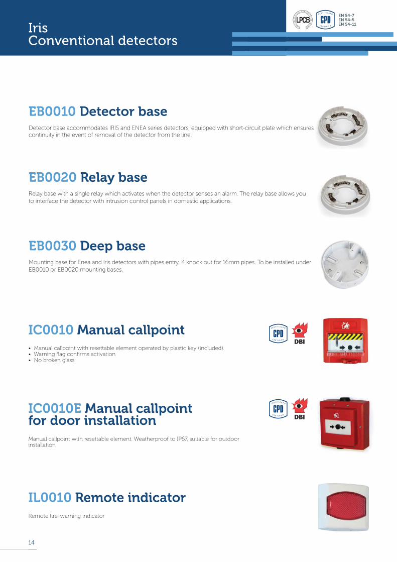
Remote fi re-warning indicator
IL0010 Remote indicator
Detector base accommodates IRIS and ENEA series detectors, equipped with short-circuit plate which ensures continuity in the event of removal of the detector from the line.
EB0010 Detector base
Relay base with a single relay which activates when the detector senses an alarm. The relay base allows you
to interface the detector with intrusion control panels in domestic applications.
EB0020 Relay base
Mounting base for Enea and Iris detectors with pipes entry, 4 knock out for 16mm pipes. To be installed under
EB0010 or EB0020 mounting bases.
EB0030 Deep base
14
EN 54-7EN 54-5EN 54-11Iris
Conventional detectors
Manual callpoint with resettable element. Weatherproof to IP67, suitable for outdoor installation
IC0010E Manual callpoint for door installation
• Manual callpoint with resettable element operated by plastic key (included).• Warning fl ag confi rms activation• No broken glass.
IC0010 Manual callpoint


ISO 9001 : 2000 Registered Company
[email protected] www.feelsef.com
DCCTINI0FIREGOVER REV2.30-20120321
P.O.Box 23767, jeddah 21436 - Saudi Arabia Tel. +966 2 6696590 _ Fax +966 2 6690741Tel. 9200 10910
Destriputed By ACC,. ISO 9001 : 2008 Registered Company
Quality By INIM, Italy


