59
Fire Detection Control Panel Series BC216 User Manual - Part B Assembly - Connecting - Commissioning Subject to change without notice © by Labor Strauss Sicherungsanlagenbau Ges.m.b.H. Wien

Fire Detection Control PanelSeries BC216User Manual - Part B
Assembly - Connecting - Commissioning
Subject to change without notice© b
y M
EP
- G
efah
renm
elde
tech
nik
Gm
bH. P
ocka
u©
by
Lab
or S
trau
ss S
iche
rung
sanl
agen
bau
Ges
.m.b
.H. W
ien

HB216BE.SAM / 0140 / AN9161206ZN5015/59/2
2 User Manual Series BC216 / Part B
All rights reserved. Under the copyright laws, no part of this manual or of the software may be multiplied, copied, disseminated, transferred by photo-technical means, reproduced, translated, or reduced to any electronic medium or machine-readable form, in whole or in part, without the prior written con-sent of Labor Strauss Sicherungsanlagenbau Ges.m.b.H., Vienna.
The information written in this User Manual has been worked out with the highest care. Neither juridical responsibility nor any kind of liability is taken foreventually remaining incorrect information. Labor Strauss Sicherungsanlagenbau Ges.m.b.H. reserves the right to change information without notice andthereby does not take any liability. The pointing out of possible errors in the manual will be gratefully accepted by the authors.
All brand names and product names used in this manual are trade names, sevice marks, trademarks, or registered trademarks of their respective owners.

Contents
1 Introduction . . . . . . . . . . . . . . . . . . . . . . . . . . . . . . . . . . . . . . . . . . . . . . . . . . . . . . . . . . . . . . . . . . . . . . . . . . . . 71.1 General . . . . . . . . . . . . . . . . . . . . . . . . . . . . . . . . . . . . . . . . . . . . . . . . . . . . . . . . . . . . . . . . . . . . . . . . . . . . . . . . 71.2 Symbols and type fonts . . . . . . . . . . . . . . . . . . . . . . . . . . . . . . . . . . . . . . . . . . . . . . . . . . . . . . . . . . . . . . . . 71.3 Important notes . . . . . . . . . . . . . . . . . . . . . . . . . . . . . . . . . . . . . . . . . . . . . . . . . . . . . . . . . . . . . . . . . . . . . . . . 71.4 Scope of delivery . . . . . . . . . . . . . . . . . . . . . . . . . . . . . . . . . . . . . . . . . . . . . . . . . . . . . . . . . . . . . . . . . . . . . . 81.4.1 Fire detection control panel BC216-1 . . . . . . . . . . . . . . . . . . . . . . . . . . . . . . . . . . . . . . . . . . . . . . . . . 81.4.2 Fire detection control panel BCnet216 . . . . . . . . . . . . . . . . . . . . . . . . . . . . . . . . . . . . . . . . . . . . . . . . 8
2 Components of the fire detection control panel Series BC216 . . . . . . . . . . . . . . . . . . . . . . . . . 92.1 Overview . . . . . . . . . . . . . . . . . . . . . . . . . . . . . . . . . . . . . . . . . . . . . . . . . . . . . . . . . . . . . . . . . . . . . . . . . . . . . . 92.2 Components of the basic version . . . . . . . . . . . . . . . . . . . . . . . . . . . . . . . . . . . . . . . . . . . . . . . . . . . . . . . 92.2.1 Case . . . . . . . . . . . . . . . . . . . . . . . . . . . . . . . . . . . . . . . . . . . . . . . . . . . . . . . . . . . . . . . . . . . . . . . . . . . . . . . . . 92.2.2 Central processing board ZTB216-1, ZTB216-2 . . . . . . . . . . . . . . . . . . . . . . . . . . . . . . . . . . . . . 102.2.3 Power unit NTB216-1 . . . . . . . . . . . . . . . . . . . . . . . . . . . . . . . . . . . . . . . . . . . . . . . . . . . . . . . . . . . . . . . 102.2.4 Display and operating board ABB216-1 . . . . . . . . . . . . . . . . . . . . . . . . . . . . . . . . . . . . . . . . . . . . . 112.2.5 Mounting bracket BW216-1 . . . . . . . . . . . . . . . . . . . . . . . . . . . . . . . . . . . . . . . . . . . . . . . . . . . . . . . . . 112.3 Function modules for detectors and modules . . . . . . . . . . . . . . . . . . . . . . . . . . . . . . . . . . . . . . . . . . 112.3.1 Conventional detector interface GIF8-1 . . . . . . . . . . . . . . . . . . . . . . . . . . . . . . . . . . . . . . . . . . . . . . 112.3.2 Loop interface LIF64-1 . . . . . . . . . . . . . . . . . . . . . . . . . . . . . . . . . . . . . . . . . . . . . . . . . . . . . . . . . . . . . 122.4 Connection of fire brigade devices . . . . . . . . . . . . . . . . . . . . . . . . . . . . . . . . . . . . . . . . . . . . . . . . . . . . 122.5 Serial interface modules SIM216-1 and SIM216-2 . . . . . . . . . . . . . . . . . . . . . . . . . . . . . . . . . . . . . 132.6 Network interface NIF5-1 . . . . . . . . . . . . . . . . . . . . . . . . . . . . . . . . . . . . . . . . . . . . . . . . . . . . . . . . . . . . . 132.7 Light-emitting diode displays . . . . . . . . . . . . . . . . . . . . . . . . . . . . . . . . . . . . . . . . . . . . . . . . . . . . . . . . . 132.8 Stand-by battery . . . . . . . . . . . . . . . . . . . . . . . . . . . . . . . . . . . . . . . . . . . . . . . . . . . . . . . . . . . . . . . . . . . . . . 132.8.1 Determining the required capacity of the stand-by battery . . . . . . . . . . . . . . . . . . . . . . . . . . . . 142.9 Auxiliary case GEH216-4 . . . . . . . . . . . . . . . . . . . . . . . . . . . . . . . . . . . . . . . . . . . . . . . . . . . . . . . . . . . . . 152.10 Battery bracket BK216-1 . . . . . . . . . . . . . . . . . . . . . . . . . . . . . . . . . . . . . . . . . . . . . . . . . . . . . . . . . . . . . 152.11 Mounting bracket BW216-1 . . . . . . . . . . . . . . . . . . . . . . . . . . . . . . . . . . . . . . . . . . . . . . . . . . . . . . . . . . 152.12 Printer . . . . . . . . . . . . . . . . . . . . . . . . . . . . . . . . . . . . . . . . . . . . . . . . . . . . . . . . . . . . . . . . . . . . . . . . . . . . . . . . 152.12.1 Operation as event printer . . . . . . . . . . . . . . . . . . . . . . . . . . . . . . . . . . . . . . . . . . . . . . . . . . . . . . . . . . . 152.12.2 Operation as service printer . . . . . . . . . . . . . . . . . . . . . . . . . . . . . . . . . . . . . . . . . . . . . . . . . . . . . . . . . 162.13 Accessories . . . . . . . . . . . . . . . . . . . . . . . . . . . . . . . . . . . . . . . . . . . . . . . . . . . . . . . . . . . . . . . . . . . . . . . . . . . 162.13.1 Printer cable . . . . . . . . . . . . . . . . . . . . . . . . . . . . . . . . . . . . . . . . . . . . . . . . . . . . . . . . . . . . . . . . . . . . . . . . 162.13.2 Connection cable between BC216-1, -2, -3 and a PC . . . . . . . . . . . . . . . . . . . . . . . . . . . . . . . . . 16
3 Assembly and installation of optional componentries . . . . . . . . . . . . . . . . . . . . . . . . . . . . . . . . . 173.1 Place of assembly . . . . . . . . . . . . . . . . . . . . . . . . . . . . . . . . . . . . . . . . . . . . . . . . . . . . . . . . . . . . . . . . . . . . . 173.2 Panel installation . . . . . . . . . . . . . . . . . . . . . . . . . . . . . . . . . . . . . . . . . . . . . . . . . . . . . . . . . . . . . . . . . . . . . 183.3 Installation of optional components . . . . . . . . . . . . . . . . . . . . . . . . . . . . . . . . . . . . . . . . . . . . . . . . . . . 193.3.1 Conventional detector interface GIF8-1, Loop interface LIF64-1 . . . . . . . . . . . . . . . . . . . . . 203.3.2 Fire brigade interface FWI2-1 . . . . . . . . . . . . . . . . . . . . . . . . . . . . . . . . . . . . . . . . . . . . . . . . . . . . . . . 203.3.3 Fire brigade interface additional board FWZ2-1 . . . . . . . . . . . . . . . . . . . . . . . . . . . . . . . . . . . . . 203.3.4 LED-display field LAB48-1 . . . . . . . . . . . . . . . . . . . . . . . . . . . . . . . . . . . . . . . . . . . . . . . . . . . . . . . . . 213.3.4.1 Insertable labels for LED-display field . . . . . . . . . . . . . . . . . . . . . . . . . . . . . . . . . . . . . . . . . . . . . 223.3.5 Serial interface modules . . . . . . . . . . . . . . . . . . . . . . . . . . . . . . . . . . . . . . . . . . . . . . . . . . . . . . . . . . . . . 233.3.6 Network interface NIF5-1 . . . . . . . . . . . . . . . . . . . . . . . . . . . . . . . . . . . . . . . . . . . . . . . . . . . . . . . . . . . 243.3.7 Relay modules RL58-1 and RL58-2 . . . . . . . . . . . . . . . . . . . . . . . . . . . . . . . . . . . . . . . . . . . . . . . . . 243.3.8 Stand-by batteries . . . . . . . . . . . . . . . . . . . . . . . . . . . . . . . . . . . . . . . . . . . . . . . . . . . . . . . . . . . . . . . . . . . 253.4 Installation of the auxiliary case GEH216-4 . . . . . . . . . . . . . . . . . . . . . . . . . . . . . . . . . . . . . . . . . . . 263.4.1 Installation of the stand-by batteries . . . . . . . . . . . . . . . . . . . . . . . . . . . . . . . . . . . . . . . . . . . . . . . . . 263.4.2 Installation of mounting brackets BW216-1 . . . . . . . . . . . . . . . . . . . . . . . . . . . . . . . . . . . . . . . . . . 26
HB216BE.SAM / 0140 / AN9161206 ZN5015/59/3
User Manual Series BC216 / Part B 3

4 Connection . . . . . . . . . . . . . . . . . . . . . . . . . . . . . . . . . . . . . . . . . . . . . . . . . . . . . . . . . . . . . . . . . . . . . . . . . . . . 284.1 General instructions . . . . . . . . . . . . . . . . . . . . . . . . . . . . . . . . . . . . . . . . . . . . . . . . . . . . . . . . . . . . . . . . . . 284.2 Power unit NTB216-1 . . . . . . . . . . . . . . . . . . . . . . . . . . . . . . . . . . . . . . . . . . . . . . . . . . . . . . . . . . . . . . . . 294.2.1 Connection of mains power, the stand-by battery and the external devices . . . . . . . . . . . . 294.2.2 Connection to the siren output . . . . . . . . . . . . . . . . . . . . . . . . . . . . . . . . . . . . . . . . . . . . . . . . . . . . . . . 304.2.3 Connection of the INFO bus . . . . . . . . . . . . . . . . . . . . . . . . . . . . . . . . . . . . . . . . . . . . . . . . . . . . . . . . . 314.2.4 Connection of the contact outputs for summary alarm and summary fault . . . . . . . . . . . . . 324.2.5 Connection of relay modules RL58-1 and RL58-2 . . . . . . . . . . . . . . . . . . . . . . . . . . . . . . . . . . . 334.3 GSSnet wiring . . . . . . . . . . . . . . . . . . . . . . . . . . . . . . . . . . . . . . . . . . . . . . . . . . . . . . . . . . . . . . . . . . . . . . . . 344.4 Conventional detector interface GIF8-1 . . . . . . . . . . . . . . . . . . . . . . . . . . . . . . . . . . . . . . . . . . . . . . . 354.5 Loop interface LIF64-1 . . . . . . . . . . . . . . . . . . . . . . . . . . . . . . . . . . . . . . . . . . . . . . . . . . . . . . . . . . . . . . . 364.6 Fire brigade interface FWI2-1 . . . . . . . . . . . . . . . . . . . . . . . . . . . . . . . . . . . . . . . . . . . . . . . . . . . . . . . . . 374.6.1 Relay contacts on the FWI2-1 . . . . . . . . . . . . . . . . . . . . . . . . . . . . . . . . . . . . . . . . . . . . . . . . . . . . . . . 384.6.2 Open collector outputs of the FWI2-1 . . . . . . . . . . . . . . . . . . . . . . . . . . . . . . . . . . . . . . . . . . . . . . . 384.6.2.1 System fault / redundant alarm . . . . . . . . . . . . . . . . . . . . . . . . . . . . . . . . . . . . . . . . . . . . . . . . . . . . . 394.6.3 Inputs of the FWI2-1 . . . . . . . . . . . . . . . . . . . . . . . . . . . . . . . . . . . . . . . . . . . . . . . . . . . . . . . . . . . . . . . . 404.7 Fire brigade interface additional board FWZ2-1 . . . . . . . . . . . . . . . . . . . . . . . . . . . . . . . . . . . . . . . 414.8 Connection of country-specific fire brigade installations . . . . . . . . . . . . . . . . . . . . . . . . . . . . . . . 414.8.1 Connection of the fire brigade installations / Austria . . . . . . . . . . . . . . . . . . . . . . . . . . . . . . . . . 424.8.1.1 Connection of the fire brigade control unit FBF58-1, the key safe adapter
AD800-1 and additional installations. . . . . . . . . . . . . . . . . . . . . . . . . . . . . . . . . . . . . . . . . . . . . . . 434.8.1.2 Connection of the fire brigade control unit FBF58-2, the key safe adapter
AD800-1 and additional installations . . . . . . . . . . . . . . . . . . . . . . . . . . . . . . . . . . . . . . . . . . . . . . 444.8.1.3 Connection of the BCnet redundant alarm line . . . . . . . . . . . . . . . . . . . . . . . . . . . . . . . . . . . . . 454.8.2 Connection of the fire brigade installations / Germany . . . . . . . . . . . . . . . . . . . . . . . . . . . . . . . 454.8.2.1 Connection of the fire brigade control unit FBF900-1, the key depot adapter
AD700 and additional installations . . . . . . . . . . . . . . . . . . . . . . . . . . . . . . . . . . . . . . . . . . . . . . . . 464.8.2.2 Connection of the fire brigade control unit FBF900-2, the key depot adapter
AD700 and additional installations. . . . . . . . . . . . . . . . . . . . . . . . . . . . . . . . . . . . . . . . . . . . . . . . . 474.9 Connection of a typical fire brigade control unit, Swiss version . . . . . . . . . . . . . . . . . . . . . . . . 484.10 Connection of a printer or computer . . . . . . . . . . . . . . . . . . . . . . . . . . . . . . . . . . . . . . . . . . . . . . . . . . . 48
5 Commissioning . . . . . . . . . . . . . . . . . . . . . . . . . . . . . . . . . . . . . . . . . . . . . . . . . . . . . . . . . . . . . . . . . . . . . . . . 505.1 Preparation . . . . . . . . . . . . . . . . . . . . . . . . . . . . . . . . . . . . . . . . . . . . . . . . . . . . . . . . . . . . . . . . . . . . . . . . . . . 505.2 Power supply connection . . . . . . . . . . . . . . . . . . . . . . . . . . . . . . . . . . . . . . . . . . . . . . . . . . . . . . . . . . . . . 515.3 Setting parameters and function tests . . . . . . . . . . . . . . . . . . . . . . . . . . . . . . . . . . . . . . . . . . . . . . . . . . 525.4 Recalculation of the bridging time . . . . . . . . . . . . . . . . . . . . . . . . . . . . . . . . . . . . . . . . . . . . . . . . . . . . 535.5 Concluding activities . . . . . . . . . . . . . . . . . . . . . . . . . . . . . . . . . . . . . . . . . . . . . . . . . . . . . . . . . . . . . . . . . 535.6 Reconditioning . . . . . . . . . . . . . . . . . . . . . . . . . . . . . . . . . . . . . . . . . . . . . . . . . . . . . . . . . . . . . . . . . . . . . . . 535.6.1 Lost installer code . . . . . . . . . . . . . . . . . . . . . . . . . . . . . . . . . . . . . . . . . . . . . . . . . . . . . . . . . . . . . . . . . . 54
6 Specifications . . . . . . . . . . . . . . . . . . . . . . . . . . . . . . . . . . . . . . . . . . . . . . . . . . . . . . . . . . . . . . . . . . . . . . . . . . 556.1 Fire detection control panel BC216-1/xx, BC216-2/xx, BC216-3/xx . . . . . . . . . . . . . . . . . . . 556.2 Power unit NTB216-1 . . . . . . . . . . . . . . . . . . . . . . . . . . . . . . . . . . . . . . . . . . . . . . . . . . . . . . . . . . . . . . . . 556.2.1 Primary alarming device . . . . . . . . . . . . . . . . . . . . . . . . . . . . . . . . . . . . . . . . . . . . . . . . . . . . . . . . . . . . 566.2.2 INFO bus . . . . . . . . . . . . . . . . . . . . . . . . . . . . . . . . . . . . . . . . . . . . . . . . . . . . . . . . . . . . . . . . . . . . . . . . . . . 566.2.3 Contact outputs for alarm relay and fault relay . . . . . . . . . . . . . . . . . . . . . . . . . . . . . . . . . . . . . . . 566.2.4 NTB auxiliary outputs . . . . . . . . . . . . . . . . . . . . . . . . . . . . . . . . . . . . . . . . . . . . . . . . . . . . . . . . . . . . . . 566.3 Conventional detector interface GIF8-1 . . . . . . . . . . . . . . . . . . . . . . . . . . . . . . . . . . . . . . . . . . . . . . . 566.4 Loop interface LIF64-1 . . . . . . . . . . . . . . . . . . . . . . . . . . . . . . . . . . . . . . . . . . . . . . . . . . . . . . . . . . . . . . . 566.5 Fire brigade interface FWI2-1 . . . . . . . . . . . . . . . . . . . . . . . . . . . . . . . . . . . . . . . . . . . . . . . . . . . . . . . . . 576.6 Fire brigade interface additional board FWZ2-1 . . . . . . . . . . . . . . . . . . . . . . . . . . . . . . . . . . . . . . . 576.7 LED-display field LAB48-1 . . . . . . . . . . . . . . . . . . . . . . . . . . . . . . . . . . . . . . . . . . . . . . . . . . . . . . . . . . 576.8 Serial interface module SIM216-1 . . . . . . . . . . . . . . . . . . . . . . . . . . . . . . . . . . . . . . . . . . . . . . . . . . . . . 57
HB216BE.SAM / 0140 / AN9161206ZN5015/59/4
4 User Manual Series BC216 / Part B

6.9 Network interface NIF5-1 . . . . . . . . . . . . . . . . . . . . . . . . . . . . . . . . . . . . . . . . . . . . . . . . . . . . . . . . . . . . . 586.10 Network cable . . . . . . . . . . . . . . . . . . . . . . . . . . . . . . . . . . . . . . . . . . . . . . . . . . . . . . . . . . . . . . . . . . . . . . . . 586.11 Auxiliary case GEH216-4 . . . . . . . . . . . . . . . . . . . . . . . . . . . . . . . . . . . . . . . . . . . . . . . . . . . . . . . . . . . . . 586.12 Battery bracket BK216-1 . . . . . . . . . . . . . . . . . . . . . . . . . . . . . . . . . . . . . . . . . . . . . . . . . . . . . . . . . . . . . 586.13 Mounting bracket BW216-1 . . . . . . . . . . . . . . . . . . . . . . . . . . . . . . . . . . . . . . . . . . . . . . . . . . . . . . . . . . 58
7 Index . . . . . . . . . . . . . . . . . . . . . . . . . . . . . . . . . . . . . . . . . . . . . . . . . . . . . . . . . . . . . . . . . . . . . . . . . . . . . . . . . . 59
HB216BE.SAM / 0140 / AN9161206 ZN5015/59/5
User Manual Series BC216 / Part B 5

HB216BE.SAM / 0140 / AN9161206ZN5015/59/6
6 User Manual Series BC216 / Part B
1 Introduction
1.1 General
The present second part of the User Manual (Part B) of the fire detection control panel Series BC216provides the competent installer with the information necessary for planning the control panel configu-ration and for the installation, connection and commissioning of the fire detection control panelsBC216-1 and BCnet216. This part of the manual is directly based on Part A of the User Manual. Thedeterminations, remarks and explanations provided there will not be repeated in the present part of themanual. It is therefore indispensable that you familiarise yourself with the contents of Part A of theUser Manual before starting installation, connection and commissioning jobs.
All information of this part of the manual for the parameter setup refers to the scope of function of theoperating software version number PL149 V4.11. Units using software with another version status maydiffer in their function from the scope of function described in this manual.
1.2 Symbols and type fonts
Particularly important text passages of this manual are marked with symbols as in Part A. The follow-ing symbols are used:
Means DANGER! Failure to observe the instructions may threaten life and health.
Means ATTENTION! Failure to observe the instructions may lead to malfunctioning of the sys-tem or damage to property.
Means TIP! The text passage contains information facilitating the operation.
Means that the country- and/or site-specific demands of the approvals of the fire detection controlpanel must be observed.
1.3 Important notes
Fire detection systems and devices must always be planned, installed and commissioned by continu-ously trained specialists. The specific training for the functions of the fire detection control panel Se-ries BC216 must be provided by Labor Strauss Sicherungsanlagenbau Ges.m.b.H. Wien (LST) or bypersons expressly authorised by LST for this purpose.
Peripheral equipment such as fire detectors, signalling devices, transmitting devices, etc., which areused in a fire detection system in addition to the control panel will only be referred to as examples inthis manual. The present manual does not provide any information concerning the expert planning orconstruction of a fire detection system. Neither does it replace the necessary technical qualification northe specific training of the installer.
Comprehensive precautions of technical circuit and design nature were taken by the manufacturer ofthe fire detection control panel Series BC216 to suppress interference through electromagnetic fields ornoise voltages.
For this reason the control panel can - under normal conditions - be employed in an unshielded cablenetwork. If shielded cables are used all the same, the shielding wires must be connected to the appro-priate terminals on the bottom part of the control panel case. Please observe the generally applicable in-stallation regulations for shielded cables.
=8/$6681
*
HB216BE.SAM / 0140 / AN9161206 ZN5015/59/7
User Manual Series BC216 / Part B Chapter 1 • Introduction 7

Prior to opening the case, switch off the mains voltage and secure to prevent switching on!Please note that with the case open, components are exposed which carry dangerous voltages with themains switched on! The protective cover of these components must not be removed.
When working on the fire detection control panel and when handling componentries, observe the usualprotective measures for the discharge of static charges: Before and during the work to be performed onthe circuit boards it is necessary to reliably discharge static charges of the body by contacting an earth-connected metallic part. It is indispensable for mains-operated tools (e.g., soldering iron) to be con-nected with protective earth or expressly approved for use on static sensitive installations. The usualprotective insulation is not sufficient.
During installation, maintenance and reconditioning, observe the applicable laws, standards and guide-lines for the installation and maintenance of fire alarm systems!
1.4 Scope of delivery
The basic version of the fire detection control panel BC216-1 is assembled at the factory and supplied100% function-tested. Please check the delivery for completeness and transport damage before assem-bling the equipment.
The modules for the connection of fire detectors, componentries and other components as well as thestand-by batteries must be ordered separately in accordance with the planned functions of the controlpanel. These components are supplied separately from the control panel and must be installed by thesystem installer. The functions of these components are described from page 9 in Chapter 2: "Compo-nents of the fire detection control panel Series BC216" and their installation in the fire detection con-trol panel is described from page 19 in Chapter 3.3: "Installation of optional components".
1.4.1 Fire detection control panel BC216-1
The basic version of the fire detection control panel BC216-1 consists of:
power unit NTB216-1,central processing board ZTB216-1,case bottom part,case cover with keypad and built-in display and operating board ABB216-1,installation bracket for the installation of optional additional componentries,enclosed packet of assembly material, replacement fuses, end of line resistors and equipmentdocumentation.
1.4.2 Fire detection control panel BCnet216
The fire detection control panel BCnet216 is not constructed as compact unit but consists of severalBCnet sectional control panels of type BC216-2 (with display and operating unit) and BC216-3 (with-out display and operating unit) which are arranged within the surveilled area of the fire detection sys-tem and are interconnected via a data line.
The basic version of every BCnet sectional control panel consists of:
power unit NTB216-1,central processing board ZTB216-2 equipped with the network interface NIF5-1,case bottom part,case cover- BC216-2: with keypad and built-in display and operating board ABB216-1- BC216-3: without keypad and display and operating board ABB216-1,installation bracket for the installation of optional additional componentries,enclosed packet of assembly material, replacement fuses and end of line resistors. The equipmentdocumentation (one copy each of User Manual Series BC216 / Part A and B, Operation Manual InShort Form, etc.) are enclosed with every delivery of a fire detection control panel BCnet216.
HB216BE.SAM / 0140 / AN9161206ZN5015/59/8
8 Chapter 1 • Introduction User Manual Series BC216 / Part B
2 Components of the fire detection control panel Series BC216
The components of the fire detection control panel Series BC216 and the optional extension modulesare briefly introduced and explained in this chapter. It also provides information for calculating thenecessary capacity of the stand-by battery.
2.1 Overview
A fire detection control panel BC216-1 or a BCnet sectional control panel of a fire detection controlpanel BCnet216 consists of the function units included in the basic version and the assemblies for op-tional installations. Please note when perusing the explanations in this manual that country-specificvariants (e.g., with the software of the central processing board ZTB216-1 or ZTB216-2) are possibleeven in the basic control panel version.
Figure 1: Expansion versions of the fire detection control panel Series BC216With the BCnet sectional control panels of the network control panel BCnet216 the network interfaceNIF5-1 is basically implemented in the optional space (7), the only vacant serial interface left istherefore optional space (6).The display and operating board ABB216-1 and the optional LED-display board LAB48-1 are at-tached to the detachable case cover.
2.2 Components of the basic version
Which components are included in the corresponding basic version of the fire detection control panelSeries BC216 is described in detail from page 8 in Chapter 1.4: "Scope of delivery".
2.2.1 Case
The two-part powder-coated steel sheet case is intended for wall surface mounting. The cover can behooked into the bottom part of the case during commissioning with the cable to the central processingboard ZTB216-1 or ZTB216-2 plugged in. Two stand-by batteries with 12V/max. 20Ah each can be in-stalled in the case even with fully extended control panel.
(1) Central processing board ZTB216-1 (BC216-1)
(2) Power unit NTB216-1(3) Display and operating board ABB216-1
(4) Function modules GIF8-1 or LIF64-1(5) Fire brigade interface FWI2-1 and FWZ2-1(6) Serial interface modules SIM216-1 oder SIM216-2
(8) Optional space for RL58-1, RL58-2, SLM1-2, SZ58-2(9) LED-display field LAB48-1
NTB216-1(2)
ZTB216-1,2SIM1,2(6)
SIM1,2(7)
ABB
(3 )
(1)
FM1 FM2
(5)(4) (4)
FWI2-1
OPT OPT OPT OPT(8) (8) (8) (8)
LAB48-1(9)
Case Series BC216
Battery
Battery Battery
Auxiliary case
216-1
Battery
or ZTB216-2 (BC216-2, BC216-3)
(only with BC216-1 and BC216-2)
(7) SIM216-1 or SIM216-2 (BC216-1) or NIF5-1 (BC216-2, BC216-3)
(not with BC216-3)
HB216BE.SAM / 0140 / AN9161206 ZN5015/59/9
User Manual Series BC216 / Part B Chapter 2 • Components of the fire detection control panel Series BC216 9

2.2.2 Central processing board ZTB216-1, ZTB216-2
With its powerful 32-bit processor system, the central processing board ZTB216-1 or ZTB216-2, re-spectively in the applicable country-specific version is largely responsible for internal signal process-ing, communication with the display and operating board, the monitoring of the detector modules, themonitoring of in- and outputs, the activation of the outputs and the communication with the peripheraldevices (e.g., signalling devices) of the system. With the help of optional interface modules, two serialinterfaces permit the connection of an external printer, the link-up to a remote maintenance system, aconnection to master systems (e.g., main panel, building management system) or with BCnet sectionalcontrol panels of a network control panel BCnet216, the connection to the GSSnet.
Upon failure of the processor system of the central computer, the processor system of the display andoperating board takes on essential tasks of the central computer. In this way it is ensured that the light-emitting diode signals, the displays and the operation facilities required in the state of alarm are alsoserviced upon failure of the central computer. Furthermore the relay HM1 on the fire brigade interfaceFWI2-1 (usually used as primary transmitting device for fire alarms) as well as the supervised sirenoutput of the power unit NTB216-1 (usually used as primary alarming device) are activated in thiscase.
The componentries of the fire detection control panel Series BC216 are connected with the centralprocessing board through a processor-supported bus system. In order to increase the failsafe capacity,this bus system is further protected by an additional diverse bus system.
2.2.3 Power unit NTB216-1
The power unit NTB216-1 serves to generate the voltages for the supply of the fire detection controlpanel, charging of the stand-by batteries, the supply of the automatic fire detectors and of the additionaldevices connected internally and externally to the control panel from the mains voltage.
In addition to this, the standard outputs for summary alarm and summary fault, the supervised sirenoutput, the INFO bus connection and 16 open collector outputs with free to set parameters are arrangedon the power unit.
The power supply unit is designed as a primary switch converter with high efficiency, resulting in lowself-heating and consequently in a high MTBF value. A power failure will be recognised after a fewseconds and shown as a fault.
The automatic monitoring of the connected stand-by batteries (including their supply cables and thefuse Si2) is accomplished through a periodical disconnection of the batteries from the charging device,simultaneous loading with a load resistor and measuring of the battery voltage under that load. Thiscomplex process ensures that - contrary to other simple monitoring methods - the supply voltage of theentire fire detection system is not subject to periodic fluctuations, but remains largely constant.
Battery monitoring is not performed for as long as mains failure is being signalled.
Monitoring of the mains voltage or the stand-by batteries can be suppressed through parameter setupfor special cases where either no mains voltage or no stand-by batteries are available (see UserManual / Part C).
A fire detection system must be supplied by two independent power sources.
The stand-by batteries are charged with current limitation and temperature optimisation. The tempera-ture sensor for controlling the final charge voltage is arranged on the right next to the terminal 20 of theNTB216-1. If the stand-by batteries are not placed in the case of the control panel (or not immediatelynext to the control panel), but at another place of installation with considerably different temperatureconditions, an external temperature sensor may be connected in place of the internal temperaturesensor.
=8/$6681
*
HB216BE.SAM / 0140 / AN9161206ZN5015/59/10
10 Chapter 2 • Components of the fire detection control panel Series BC216 User Manual Series BC216 / Part B
An electronic switching device disconnects the stand-by batteries from the charging device in theevents of short-circuit or overload, preventing repercussions for the control panel or the BCnet sec-tional control panel. The stand-by batteries are disconnected from the control panel also when there is arisk of total discharge of the battery.
For reasons of safety a totally discharged stand-by battery is no longer charged automatically by thecharging device. The connections for the external devices and those within the control panel are fuse-protected separately, fuse failure is recognised immediately and displayed as a fault.
The entire installation connected to this control panel or BCnet sectional control panel is subject toearth leakage monitoring by the power unit NTB216-1. If earth leakage occurs anywhere within the firealarm cable system, this is indicated on the fire detection control panel as a fault/earth leakage.
The earth leakage monitoring can be taken out of service through parameter setup for special caseswhere a connection of the cable network with earth has been established on purpose (e.g., in an intrin-sically safe area by the connection of a cable section with the local equipotential busbar) (see UserManual / Part C).
Since the fire detection control panel Series BC216 indicates any malfunction of the system, whichmay be caused by multiple earth leakage, as a fault of that function, indication of simple earth leakageis not required by the European Standard EN54.
2.2.4 Display and operating board ABB216-1
The display and operating board ABB216-1 has its own processor system to activate the LC-displayand light-emitting diodes and to enable the operation of the fire detection control panel. An alarm orfault is acoustically signalled by the buzzer arranged on the display and operating board.
Upon failure of the display and operating board processor, the processor of the central processingboard ensures that the LED displays required in the state of alarm are activated and the operation ofthe built-in buzzer and the supervised siren output of the NTB216-1 is maintained.
2.2.5 Mounting bracket BW216-1
A standardly built-in componentry mounting bracket, equipped with holes according to the LST stan-dard grid, permits the installation of additional componentries. Relay modules RL58-1 or RL58-2, con-trol zone modules SLM1-2, siren supervising modules SZ58-2, isolator modules and othercomponentries for instance can be quickly and easily installed in this way.
2.3 Function modules for detectors and modules
Function modules for conventional detector technology and for intelligent ADM- or ADMPRO-technology are provided for the connection of fire detectors, fault detectors, technical detectors, controlmodules and monitor modules. Installation space in the central processing board is provided for two ofthese function modules. Depending on the size of the system, the control panel or the BCnet sectionalcontrol panel can be equipped either with only one, two identical or two different function modules.
2.3.1 Conventional detector interface GIF8-1
The conventional detector interface GIF8-1 is employed for the connection of conventional detectors.Up to 8 detector lines, each comprising one detector zone in addressable conventional technology, canbe connected to this module. Depending on your requirements, one or two conventional detector inter-faces can be installed in the function module locations of the central processing board (ST2 or ST3, seefrom page 20 in Chapter 3.3.1: "Conventional detector interface GIF8-1, Loop interface LIF64-1") andthereby up to 16 detector lines can be connected.
Detector line is the term used for the (usually branched) cable path connecting the detectors with thecontrol panel. A detector zone is formed by the detectors of a surveilled area sharing a common dis-play on the fire detection control panel. With the conventional detector interface GIF8-1, all detectorsconnected to a detector line form one detector zone.
=8/$6681
*
HB216BE.SAM / 0140 / AN9161206 ZN5015/59/11
User Manual Series BC216 / Part B Chapter 2 • Components of the fire detection control panel Series BC216 11

2.3.2 Loop interface LIF64-1
The loop interface LIF64-1 is employed for the use of the intelligent analogue technology. A loop withbi-directional data traffic for the connection of detectors and modules of ADM- or ADMPRO-technology can be connected to it. The detectors and modules connected to a loop can be combinedinto a total of 128 independent zones.
Due to organizational reasons the total number of zones serviced by the fire detection control panelBC216-1 or by each BCnet sectional control panel of the fire detection control panel BCnet216 mustnot exceed 144.
Depending on your requirements, you can install one or two loop interfaces at the space for functionmodules provided in the central processing board (plug-in port ST2 or ST3, see from page 20 in Chap-ter 3.3.1: "Conventional detector interface GIF8-1, Loop interface LIF64-1"), accomplishing up to 144detector or actuation zones in this way.
During the configuration, the installer determines through parameter setup of each loop interfacewhether ADM-technology (99 detectors + 99 modules per loop) or ADMPRO-technology (126 ad-dress points per loop) are to be processed.
2.4 Connection of fire brigade devices
The fire brigade interface FWI2-1 is available for the connection to a designated alarm respondent(e.g., the fire brigade).
Two relays (HM1 and HM2) with free to set parameters and dry change-over contacts for passingon alarms in various combinations,9 inputs with free to set parameters,8 outputs with free to set parameters, and1 output for system fault
are arranged on this interface for the connection of a country-specific fire brigade control unit, a keysafe or a key depot adapter and other equipment. Individual functions can also be assigned to the inputsor outputs with free to set parameters (see User Manual / Part C).
The fire brigade interface additional board FWZ2-1 that fits onto the fire brigade interface FWI2-1 isprovided for the line-monitored connection of a transmitting device. With this addition it is possible toaccomplish two independent outputs for transmitting devices (e.g., for alarm and/or fault signals)which are monitored for interruption and short circuit. The line monitoring current of these outputs canbe parameterised.
Basically, a fire brigade interface FWI2-1 and a fire brigade interface additional board FWZ2-1 can bebuilt into every BCnet sectional control panel with the network fire detection control panel BCnet216.Either further in- and outputs for general use (e.g., for actuations) are provided for the control panel or,with main- and sub-control panel configuration, additional sectional fire brigade control units, sectionalkey safes, etc. can be controlled.
With the fire detection control panel BC216-1 or the BCnet sectional control panel BC216-2, in caseof a failure of the processor system of the ZTB216-1 or ZTB216-2, the siren output of the power unitNTB216-1 and its connected local devices as well as the relay HM1 (which is usually used as primarytransmitting device) on the fire brigade interface FWI2-1 are activated in the event of an alarm. As anoption it is additionally possible to activate the relay HM2 and the FWI-OC-output terminal 14 (seefrom page 38 in Chapter 4.6.1: "Relay contacts on the FWI2-1" and from page 38 in Chapter 4.6.2:"Open collector outputs of the FWI2-1"). A failure of the processor system of the ZTB216-2 of a non-operatable BCnet sectional control panel BC216-3 ("black box control panel") is displayed as fault inthe overall system. Nevertheless, the local signalling devices and transmitting devices are not servicedin case of alarm.
HB216BE.SAM / 0140 / AN9161206ZN5015/59/12
12 Chapter 2 • Components of the fire detection control panel Series BC216 User Manual Series BC216 / Part B

2.5 Serial interface modules SIM216-1 and SIM216-2
The fire detection control panel BC216-1 can be expanded with two, every BCnet sectional controlpanel of the network fire detection control panel BCnet216 can be expanded with one serial interfaceof type RS232-C. The serial interface modules SIM216-1 and SIM216-2 serve to convert the processorsignals to the standardised interface levels.
The serial interface module SIM216-1 is designed with isolated potentials and is therefore suitable forthe connection of devices, which are not themselves designed with isolated potentials. Typical applica-tions for this are: Printers, PC with parameter setup software PARSOFT-1 or -2x, etc.
The serial interface module SIM216-2 has no potential separation and is therefore suitable only for theconnection of a device having its own internal potential separation. This interface module also supportshandshake lines of the interface. Typical applications for this are: Remote maintenance via modem, re-mote parameter setup via modem, etc.
2.6 Network interface NIF5-1
The connection of the BCnet sectional control panels of a network fire detection control panelBCnet216 to the redundant data line which combines the BCnet sectional control panels to an overallcontrol panel is constructed in serial technology via the network interface NIF5-1 which is pluggedonto the central processing board ZTB216-2. Besides converting the processor signals to the RS485 in-terface level of the GSSnet, this componentry also realizes error management for faults of the circularlyconstructed GSSnet data line via intelligent short circuit isolators and interface change-over switches.
2.7 Light-emitting diode displays
The optionally applicable LED-display field LAB48-1 contains 48 freely adjustable light-emitting di-ode pairs (one red and one yellow light-emitting diode each) to indicate the activation, fault or switch-off conditions of a defined part of the system. The LED-display field LAB48-1 is controlled by the dis-play and operating board ABB216-1. Insertable labels serve to individually name the light-emittingdiodes.
2.8 Stand-by battery
The case of the fire detection control panel Series BC216 is designed to accommodate 2 series-connected stand-by batteries of 12V/17Ah (max. 20Ah). If the capacity of the built-in batteries is notsufficient, the capacity can be doubled by parallel-connecting another 17Ah arrangement (see frompage 15 in Chapter 2.9: "Auxiliary case GEH216-4" and from page 29 in Chapter 4.2.1: "Connection ofmains power, the stand-by battery and the external devices"). These additional batteries should be in-stalled as close as possible to the built-in batteries in order to ensure identical temperature conditionsfor all batteries.
Stand-by battery charging is automatically adapted by the control panel to the operating temperature ofthe batteries.
Only 24V units (i.e., 2 series-connected individual 12V-batteries) may be connected in parallel. Theindividual batteries must be of the same type.In order to meet the requirements of the 24-hour charging time, the total capacity of the stand-by bat-teries connected to the BC216-1 or to a BCnet sectional control panel of a BCnet216 must not exceed34Ah (e.g., 2 x 17Ah connected in parallel).
Use the auxiliary case GEH216-4 which fits to the fire detection control panel Series BC216 for in-stalling additional stand-by batteries or other additional elements, see from page 15 in Chapter 2.9:"Auxiliary case GEH216-4".
The stand-by batteries can generally be operated in any position, but the upright position is preferred(with the connections facing up). Ensure that the connections of the batteries do not make electrical
=8/$6681
*
HB216BE.SAM / 0140 / AN9161206 ZN5015/59/13
User Manual Series BC216 / Part B Chapter 2 • Components of the fire detection control panel Series BC216 13

contact with the case or other metallic parts during the installation or during subsequent operation, thismight destroy the battery or the fire detection control panel!
Connect the connection lines to the stand-by battery only when all the cabling work on the system hasbeen completed and checked!
Use only maintenance-free, sealed stand-by batteries with fixed electrolyte and low self-discharge,which are specially suited and approved for emergency power supply of electronic security systems instandby parallel mode.
Do not under any circumstances use batteries of a type other than the type provided as stan-dard, which has been specially designed for use in security systems! The charging process em-ployed in the fire detection control panel is designed for this type of battery, other batteriescould start leaking in operation or even burst - the fire detection control panel could bedestroyed!
2.8.1 Determining the required capacity of the stand-by battery
In general the required stand-by battery capacity is dependent onthe system current during the mains failure,the system current during acoustic and optical alarm and on the required mains failure bridging time.
A separate stand-by battery is installed in every BCnet sectional control panel of the network fire de-tection control panel BCnet216. The required capacity of these batteries is to be harmonized with thesystem parts connected to the corresponding BCnet sectional control panel.
The system current to be supplied by the stand-by battery upon mains failure must be calculated duringthe project phase. To do so, take the quiescent current values from the data sheets of the devices youintend using in the system. The values of the control panel itself can be found from page 55 in Chapter6: "Specifications". Please note that the fire detection control panel will be subject to a fault status inthe event of mains failure!
Avoid all loads not absolutely necessary for the operation of the system. Any permanently connecteddevice will be a burden on the stand-by battery upon mains failure. As part of commissioning the en-tire system, check in the state of mains shut down to see if the measured system current correspondswith the calculated value.
Determine the current consumption in the state of alarm from the data sheets of the acoustic alarmingdevices (sirens) and the optical alarming devices (flashlight) employed. Take into account also thepower consumption of connected transmitting devices and other facilities (e.g., a fire brigade key safeor a fire brigade key depot).
The required mains failure bridging time is dependent on the respective installation regulations and thelocal conditions.
A typical requirement, e.g., is that a fire detection system must be able to recognise an alarm even72 hours after the mains failure started and to signal such alarm optically and acoustically for 30minutes.
Without taking into account reserves, efficiency, etc., you can approximately determine the minimumcapacity of the required stand-by batteries, using the above mentioned installation regulations as a baseas follows
CMIN = 72 × IMAINS FAILURE + 0.5 × IAL whereas
CMIN ... Minimum capacity in [Ah]IMAINS FAILURE ... total system current during mains failure in [A], without raising alarmIAL ... entire system current while raising the alarm in [A]
=8/$6681
*
HB216BE.SAM / 0140 / AN9161206ZN5015/59/14
14 Chapter 2 • Components of the fire detection control panel Series BC216 User Manual Series BC216 / Part B

With a BCnet sectional control panel of the network fire detection control panel BCnet216 the currentrequired for supplying the system section which is serviced by the corresponding BCnet sectional con-trol panel (including the BCnet sectional control panel itself) is referred to as "system current".
Add a safety allowance to this calculated minimum value to compensate for exemplary fluctuations orcapacity losses caused by the effect of temperature and ageing.
2.9 Auxiliary case GEH216-4
The auxiliary case GEH216-4 with the same dimensions as the control panel case is available for theinstallation of additional stand-by batteries if higher current is required by the fire detection system orwhen optional assemblies are installed.
The auxiliary case can house eitherfour batteries 12V/17Ah (one battery bracket BK216-1 is required additionally) and a mountingbracket BW216-1 ortwo batteries 12V/17Ah (a maximum of 20Ah each) and four mounting brackets BW216-1.
2.10 Battery bracket BK216-1
An auxiliary case GEH216-4 can house up to four stand-by batteries of 12V/max. 20Ah. Two stand-bybatteries are arranged on the bottom of the auxiliary case, further two batteries can be installed by us-ing the battery bracket BK216-1 which is screwed on to the bottom part of the case.
2.11 Mounting bracket BW216-1
Mounting brackets BW216-1 are used for the installation of additional componentries fitting the LSTstandard grid by using plastic spacers.
2.12 Printer
A printer can be connected to the fire detection control panel BC216-1 or to every BCnet sectional con-trol panel of the network control panel BCnet216 either permanently or only for service purposes viaone of the two serial interfaces. The printer can also be installed separately from the control panelwhile the cable length is limited to 5m.
The control panel is prepared for the connection of the following types of printer:Seiko DPU-414, Art. Nr. 227003Upright unit with particularly small dimensions (160mm × 170mm × 66.5mm)Thermal paper, 28m/roll, automatic change-over to offline mode on paper end80 characters per lineOperation via power supply unit and optional Ni-Cd batteryRequired printer cable: Port D-SUB 9-pin, plug D-SUB 9-pin, max. length 5mEpson LX-300, Art. Nr. 227008Upright unit with the dimensions 366mm × 275mm × 132mmMatrix printer, 9 needlesStandard reel paper80 characters per lineMains operationRequired printer cable: Port D-SUB 9-pin, plug D-SUB 25-pin, max. length 5m
Both types of printer require the installation of a serial interface module SIM216-1 in the control panel.
2.12.1 Operation as event printer
The events are recorded with date and time, a continuous number and the additional text information(e.g., location) as a function of the set printer filter (see User Manual / Part C).
HB216BE.SAM / 0140 / AN9161206 ZN5015/59/15
User Manual Series BC216 / Part B Chapter 2 • Components of the fire detection control panel Series BC216 15

2.12.2 Operation as service printer
This operation type of the printer was installed especially for supporting the service and maintenancetechnician. As installer you can select from the following print-out possibilities for the connected andset-up printer (see User Manual Series BC216 / Part A, menu point [System] - [Print-out]):
Service print-out: On request the printer prints the contents of the event memory, considering theset printer filter.Settings print-out: On request the printer prints a summary of the entire control panel configura-tion (hardware and parameter setup).Measured value print-out: The printer prints the measured values of the connected ADM orADMPRO detectors and modules. The measured value print-out is available as an unique statusprint-out of one or several elements (e.g., all detectors of one zone) or as an automatically and con-tinuously operating current measuring value output for a single element.
2.13 Accessories
2.13.1 Printer cable
Standard cables obtainable in specialized stores are used as connection cables for the optional printersSeiko DPU-414 and Epson LX-300 for connection to the serial interface module SIM216-1. The struc-ture of these cables is shown in the following figures.
SIM216-1socketD-SUB 9 pin
RxD 2TxD 3
GND 5CTS 8
length max. 5m2 TxD3 RxD5 GND8 CTS
Seiko DPU-414connectorD-SUB 9 pin
Figure 2: Printer cable for Seiko DPU-414 (Art. Nr. 227007, length: 1,8m)
SIM216-1socketD-SUB 9 pin
RxD 2TxD 3
GND 5CTS 8
length max. 5m2 TxD3 RxD7 GND20 DTR
Epson LX-300connectorD-SUB 25 pin
Figure 3: Printer cable for Epson LX-300
2.13.2 Connection cable between BC216-1, -2, -3 and a PC
In order to connect a PC (Notebook) to the fire detection control panel BC216-1 or to a BCnet sectionalcontrol panel BC216-2 or BC216-3 you require a standard cable obtainable in specialized stores. Thestructure of the cable is shown in the following figure.
SIM216-1socketD-SUB 9 pin
RxD 2TxD 3
GND 5
length max. 3m3 TxD2 RxD5 GND
PCsocketD-SUB 9 pin
In each of the two D-SUB ports it is necessary to additionally connect the ports 1 with 4 and 7 with 8.
Figure 4: Connection cable control panel - PC
HB216BE.SAM / 0140 / AN9161206ZN5015/59/16
16 Chapter 2 • Components of the fire detection control panel Series BC216 User Manual Series BC216 / Part B

3 Assembly and installation of optional componentries
This chapter presents the assembly of the fire detection control panel BC216-1, the BCnet sectionalcontrol panels of the fire detection control panel BCnet216 and the auxiliary case GEH216-4 as well asthe installation of the optional componentries and facilities. You can install and wire-up the optionalcomponentries beforehand so that you merely have to assemble and connect the already assembled con-trol panel on site. Parameter setup (see User Manual / Part C) can be carried out beforehand also, ex-cept for date and time the input data will be preserved indefinitely even without supply voltage.
Do not under any circumstances transport the fire detection control panel or the auxiliary casewith the stand-by batteries installed! It is indispensable to remove the batteries from the case fortransporting (even over short distances!).
Attention with MOS components! The MOS components employed in the device can be destroyedby static loads with the device opened. Prior to and during the work carried out on the printed circuitboards it is necessary to reliably discharge static charges of the body by contacting an earth-connectedmetallic part (e.g., the earth-connected control panel case).
Figure 5: Opened case of the fire detection control panel BC216-1A ... Connection cable from the display and operating board ABB216-1
to the central processing board ZTB216-1 / connector ST1B ... FASTON Tabs for the earth connection of the case coverC ... Mounting bracket for optional componentriesD ... Equipotential busbar connectionE ... Terminal connections for shielding wires of shielded cables
3.1 Place of assembly
The fire detection control panel BC216-1 and every BCnet sectional control panel of the network firedetection control panel BCnet216 must be installed in a clean and dry room on a stable wall surface.The room temperature must range between -5°C and +50°C, the relative humidity of the air must notexceed 90%. Protect the control panel against splashing water and other mechanical and chemicaleffects.
The place of assembly must be easily accessible for the public safety personnel (e.g., the fire brigade).Coordinate the place of assembly with the officials concerned. The control panel must be installed at alevel above ground at which operation and reading of the displays is possible without obstacle.
The fire development risk must be low in the room where the fire detection control panel is to bemounted. The room must be monitored by the fire detection system.
=8/$6681
*
HB216BE.SAM / 0140 / AN9161206 ZN5015/59/17
User Manual Series BC216 / Part B Chapter 3 • Assembly and installation of optional componentries 17
3.2 Panel installation
The control panel is installed in a 2-piece powder-coated steel sheet case (consisting of the bottom partand the cover). The cover is detachable and can be hooked into the bottom part with the connection ca-ble plugged in to facilitate commissioning. All necessary mounting elements (bolts and plugs) are in-cluded in the package accompanying the control panel.
Figure 6: Control panel caseA ... dimensions of the control panel case, position of the installation boresB ... swivel area of the case cover (approximate values)C ... case cover hooked into the bottom part of the case
At least 25mm of vacant space must be available below the case to remove the case cover from thebottom part! This minimum vacant space is sufficient for removing the case cover but not for tilting,corresponding to figures 6B or 6C.
Loosen the two mounting screws of the case cover and tilt the cover forward. Disconnect the flat ca-ble connecting the display and operating board with the central processing board ZTB216-1 orZTB216-2 from the central processing board. Loosen the two earth connections from the case andremove the case cover.
Mark the three mounting points on the wall, drill the mounting holes with a drill suitable for theplugs, insert the plugs in the drilled holes and provisionally screw the mounting screws in the twoupper plugs.
Suspend the control panel from the two screws screwed into the wall. Pull the already installed ca-bles through the cable openings at the back of the case, ensuring the proper separation of cables car-rying mains voltage and low-voltage.
Secure the case using the lower mounting screw. Then tighten the two upper screws, adjusting ir-regular mounting surfaces through the insertion of spacer elements if required. Ensure that no cablesare squashed and that the case is not bent by an uneven mounting surface during tightening.
Install the optional componentries at the places provided for this purpose, see from page 19 in Chap-ter 3.3: "Installation of optional components".
Carry out all cabling jobs according to your installation documentation taking into account the con-nection diagrams shown from page 28 in Chapter 4: "Connection" and the installation regulationsfor fire alarm systems. Ensure that mains power is not switched on while cabling jobs are inprogress!
When using shielded cables, connect the shielding wires with the case (earth). The terminal connec-tions on the case bottom part below the function modules are provided for this purpose. Bare shield-ing wires must be insulated by fitting an insulation tube or similar measures to prevent shortcircuits.
A B
C
HB216BE.SAM / 0140 / AN9161206ZN5015/59/18
18 Chapter 3 • Assembly and installation of optional componentries User Manual Series BC216 / Part B

The fire detection control panel Series BC216 is comprehensively protected against the effects of elec-trical faults. Shielded cables are therefore not required for the safe operation of the control panel undernormal ambient conditions.
Hook in the case cover and reconnect the flat cable to the connector ST1 of the central processingboard ZTB216-1 or ZTB216-2 (see survey figure from page 19 in Chapter 3.3: "Installation of op-tional components") and the two earth connections.
When closing the case ensure that the bottom part of the case is introduced in the lateral guides ofthe case cover and no cable is squashed. Secure the case cover with the two mounting screws pro-vided for this purpose.
It is indispensable for the case of the control panel to be earthed in operation! For this purpose connectthe control panel case with the equipotential busbar connection of the local electrical installation. En-sure that protective earth is connected to the earth connection terminal on the bottom part of the case,the connection between the protective earth connection of the mains terminal and the bottom part ofthe case is established and the case cover and the bottom part of the case are electrically connectedwith the two earth connection lines.
3.3 Installation of optional components
All installation work must only be carried out with the fire detection control panel in the de-energisedstate. Mains power must be switched off and locked to prevent switching on and the stand-by batteriesmust be disconnected.
It is absolutely essential that the protective earth conductor and the equipotential busbar are connectedto the bottom part of the case to ensure the required discharge of electrostatic charges.
All optional modules are delivered in an antistatic package. Before removing a module from the pack-age it is essential that you discharge yourself by contacting an earth-connected metallic part (e.g., thecontrol panel case). Plug the componentry taken from the package in the connector of the control panelprovided for this purpose and tighten the screws. If you remove a componentry it must be immediatelyplaced in the antistatic package without storing the module anywhere in between.
Figure 7: Survey of the connection of optional componentries to the central processing board ZTB216-1 orZTB216-2.A ...Place of installation for fire brigade interface FWI2-1B ...Place of installation for function module FM1C ...Place of installation for function module FM2D ...Connector ST5: Power unit NTB216-1E ...Connector ST4: Fire brigade interface FWI2-1F ...Connector ST2: Function module FM1G ...Connector ST3: Function module FM2H ...Connector ST1: Display and operating board ABB216-1I ... Connector ST8: Connector for PC keyboardJ ... Connector ST6: "Serial interface 1" serial interface module SIM216-1 or SIM216-2K ...Connector ST7: "Serial interface 2"
HB216BE.SAM / 0140 / AN9161206 ZN5015/59/19
User Manual Series BC216 / Part B Chapter 3 • Assembly and installation of optional componentries 19
BC216-1: serial interface module SIM216-1 or SIM216-2 BCnet sectional control panel of a BCnet216: NIF5-1L ... Connector ST9: 10-pin connector for diagnostic functions during the manufacturing process
3.3.1 Conventional detector interface GIF8-1, Loop interface LIF64-1
Ensure that the control panel is de-energised. Reliably discharge static loads also during the followingactivities by touching the control panel case connected to the protective conductor.
Plug the first conventional detector or loop interface in the function module space 1 (ST2) of thecentral processing board ZTB216-1 or ZTB216-2 and secure the module to the case bottom part us-ing the two enclosed screws.
Plug the second conventional detector or loop interface (if required) into the function module space2 (ST3) of the central processing board and secure it to the case bottom part with the two enclosedscrews.With a BCnet sectional control panel of a fire detection control panel BCnet216 the mounting boltsof the function module space 2 are additionally used for securing the terminal board of the networkinterface NIF5-1. In this case you have to remove the two hexagon bolts which secure the terminalboard and plug the corresponding function module (GIF8-1, LIF64-1) in the central processingboard as priorly described; secure the function module by tightening the hexagon bolts. Succes-sively, secure the terminal board of the NIF5-1 on these bolts by using the screws enclosed withevery function module (further hints see from page 24 in Chapter 3.3.6: "Network interfaceNIF5-1").
Ensure that the conventional detector or loop interfaces are plugged in only in the function modulespaces provided for this purpose (ST2 or ST3).To ensure a safe earth connection the mounting screws must be adequately tightened.
3.3.2 Fire brigade interface FWI2-1
Verify that the control panel is de-energised. Reliably discharge static loads also during the followingactivities by touching the control panel case connected to the protective conductor.
Plug the fire brigade interface FWI2-1 into the plug-in space 4 (ST4) of the central processing boardZTB216-1 or ZTB216-2 and secure the assembly to the case bottom part with the two enclosedscrews.
Ensure that the fire brigade interface is only plugged into the intended plug-in space ST4.The mounting screws must be sufficiently tightened to ensure safe earth connection.
If you require monitored outputs for transmitting devices, the fire brigade interface additional boardFWZ2-1 must be fitted to the FWI2-1 before installing the fire brigade interface in the control panel.
3.3.3 Fire brigade interface additional board FWZ2-1
Install the fire brigade interface additional board on the fire brigade interface with the help of the threeenclosed hexagon bolts as shown in the following.
HB216BE.SAM / 0140 / AN9161206ZN5015/59/20
20 Chapter 3 • Assembly and installation of optional componentries User Manual Series BC216 / Part B

Figure 8: Assembly of the fire brigade interface additional board FWZ2-1 to the fire brigade interface FWI2-1.The power unit NTB216-1 positioned in front was removed for more detailed photographic presenta-tion.A ... Enclosed hexagon bolts
Ensure that the control panel is de-energised. Reliably discharged static loads also during the followingactivities by touching the control panel case connected to the protective conductor.
If the fire brigade interface FWI2-1 is already installed in the control panel, it has to be removed.
Attach one of the supplied hexagon bolts to the fire brigade interface in the centre bore below thepin terminal ST2 by means of the enclosed nut.
Plug the fire brigade interface FWI2-1 into the plug-in space 4 (ST4) of the central processing boardZTB216-1 or ZTB216-2 and secure it to the case bottom part using the remaining two hexagonbolts.
Plug the fire brigade interface additional board FWZ2-1 into the pin terminal ST2 of the fire brigadeinterface FWI2-1 provided for this purpose. Ensure that all 16 pins of the pin terminal are engagedin the connector and are not bent. When plugging in, support the fire brigade interface FWI2-1 frombehind to avoid excessive mechanical load on the plug connection ST4.
Secure the fire brigade interface additional board to the hexagon bolts using the three enclosed re-cessed head screws.
To ensure secure earth connection, adequately tighten the hexagon bolts and the mounting screws.
3.3.4 LED-display field LAB48-1
The LED-display field consists of two printed circuit boards, which are interconnected when delivered.These two printed circuit boards must be separated prior to installation. To do so, position the unitagainst a solid edge along the provided scored fracture line and break the unit over this edge using bothhands. Ensure that the connection cable connecting the two printed circuit boards and the componentsmounted on the printed circuit boards are not damaged.
Prior to and during the work to be conducted on the printed circuit boards, static charges of the bodymust be reliably discharged by contacting an earthed metallic part.
Slide the enclosed plastic spacer tubes onto the 6 threaded pins in the interior of the case cover, fit eachof the printed circuit boards onto 3 of the threaded pins and secure the printed circuit boards to thethreaded pins using the enclosed nuts according to the following figure. Connect the flat cable to theconnector ST2 of the display and operating board ABB216-1.
HB216BE.SAM / 0140 / AN9161206 ZN5015/59/21
User Manual Series BC216 / Part B Chapter 3 • Assembly and installation of optional componentries 21
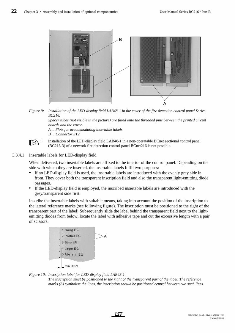
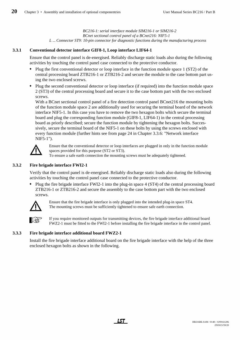
Figure 9: Installation of the LED-display field LAB48-1 in the cover of the fire detection control panel SeriesBC216.Spacer tubes (not visible in the picture) are fitted onto the threaded pins between the printed circuitboards and the cover.A ... Slots for accommodating insertable labelsB ... Connector ST2
Installation of the LED-display field LAB48-1 in a non-operatable BCnet sectional control panel(BC216-3) of a network fire detection control panel BCnet216 is not possible.
3.3.4.1 Insertable labels for LED-display field
When delivered, two insertable labels are affixed to the interior of the control panel. Depending on theside with which they are inserted, the insertable labels fulfil two purposes:
If no LED-display field is used, the insertable labels are introduced with the evenly grey side infront. They cover both the transparent inscription field and also the transparent light-emitting diodepassages.If the LED-display field is employed, the inscribed insertable labels are introduced with thegrey/transparent side first.
Inscribe the insertable labels with suitable means, taking into account the position of the inscription tothe lateral reference marks (see following figure). The inscription must be positioned to the right of thetransparent part of the label! Subsequently slide the label behind the transparent field next to the light-emitting diodes from below, locate the label with adhesive tape and cut the excessive length with a pairof scissors.
Figure 10: Inscription label for LED-display field LAB48-1The inscription must be positioned to the right of the transparent part of the label. The referencemarks (A) symbolise the lines, the inscription should be positioned central between two such lines.
HB216BE.SAM / 0140 / AN9161206ZN5015/59/22
22 Chapter 3 • Assembly and installation of optional componentries User Manual Series BC216 / Part B
You can also use a cardboard or paper label, which you previously printed with a laser printer insteadof the plastic strip. Print examples for such insertable labels for use with some standard programmescan be found on the CD on which the parameter setup software PARSOFT-1 is delivered (file names:LEDBeschrift.wk4, LEDBeschrift.123, LEDBeschrift.xls). Ensure that the inserted strip does notcover the light-emitting diodes.
On no account should you use sharp or pointed tools to pull out an inserted strip. The surface of thekeypad is highly sensitive to scratching on the inside and these scratches are also visible from theoutside.
3.3.5 Serial interface modules
By using the enclosed hexagon bolts, install the serial interface modules SIM216-1 and SIM216-2 onthe central processing board ZTB216-1 on the plug-in spaces ST6 or ST7 or on plug-in space ST6when using the central processing board ZTB216-2 of a BCnet sectional control panel. Depending onthe pin terminals to which you connect the interface module, the interface module will be addressed as"Serial interface 1" (ST6) or as "Serial interface 2" (ST7) during parameter setup.
With all BCnet sectional control panels of the fire detection control panel BCnet216, plug-in spaceST7 of the central processing board ZTB216-2 is reserved for the connection to the GSSnet via thenetwork interface NIF5-1.
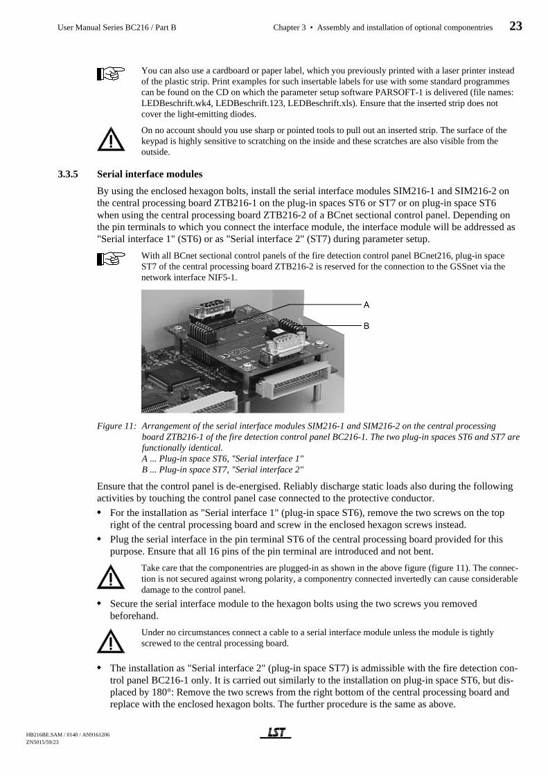
Figure 11: Arrangement of the serial interface modules SIM216-1 and SIM216-2 on the central processingboard ZTB216-1 of the fire detection control panel BC216-1. The two plug-in spaces ST6 and ST7 arefunctionally identical.A ... Plug-in space ST6, "Serial interface 1"B ... Plug-in space ST7, "Serial interface 2"
Ensure that the control panel is de-energised. Reliably discharge static loads also during the followingactivities by touching the control panel case connected to the protective conductor.
For the installation as "Serial interface 1" (plug-in space ST6), remove the two screws on the topright of the central processing board and screw in the enclosed hexagon screws instead.
Plug the serial interface in the pin terminal ST6 of the central processing board provided for thispurpose. Ensure that all 16 pins of the pin terminal are introduced and not bent.
Take care that the componentries are plugged-in as shown in the above figure (figure 11). The connec-tion is not secured against wrong polarity, a componentry connected invertedly can cause considerabledamage to the control panel.
Secure the serial interface module to the hexagon bolts using the two screws you removedbeforehand.
Under no circumstances connect a cable to a serial interface module unless the module is tightlyscrewed to the central processing board.
The installation as "Serial interface 2" (plug-in space ST7) is admissible with the fire detection con-trol panel BC216-1 only. It is carried out similarly to the installation on plug-in space ST6, but dis-placed by 180°: Remove the two screws from the right bottom of the central processing board andreplace with the enclosed hexagon bolts. The further procedure is the same as above.
HB216BE.SAM / 0140 / AN9161206 ZN5015/59/23
User Manual Series BC216 / Part B Chapter 3 • Assembly and installation of optional componentries 23
3.3.6 Network interface NIF5-1
The network interface NIF5-1 is necessary for every BCnet sectional control panel of a fire detectioncontrol panel BCnet216 for the connection to the network. With every BCnet sectional control panel itis installed as standard on plug-in space ST7 of the central processing board ZTB216-2 at delivery.
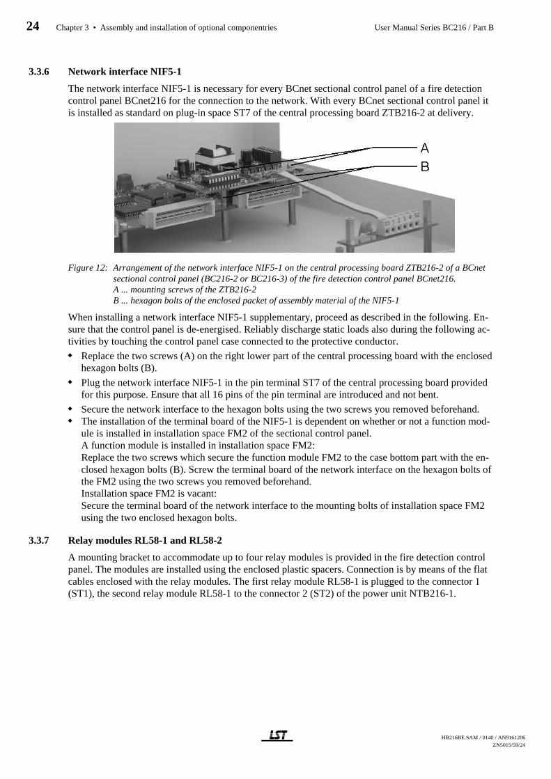
Figure 12: Arrangement of the network interface NIF5-1 on the central processing board ZTB216-2 of a BCnetsectional control panel (BC216-2 or BC216-3) of the fire detection control panel BCnet216.A ... mounting screws of the ZTB216-2 B ... hexagon bolts of the enclosed packet of assembly material of the NIF5-1
When installing a network interface NIF5-1 supplementary, proceed as described in the following. En-sure that the control panel is de-energised. Reliably discharge static loads also during the following ac-tivities by touching the control panel case connected to the protective conductor.
Replace the two screws (A) on the right lower part of the central processing board with the enclosedhexagon bolts (B).
Plug the network interface NIF5-1 in the pin terminal ST7 of the central processing board providedfor this purpose. Ensure that all 16 pins of the pin terminal are introduced and not bent.
Secure the network interface to the hexagon bolts using the two screws you removed beforehand.The installation of the terminal board of the NIF5-1 is dependent on whether or not a function mod-ule is installed in installation space FM2 of the sectional control panel.A function module is installed in installation space FM2:Replace the two screws which secure the function module FM2 to the case bottom part with the en-closed hexagon bolts (B). Screw the terminal board of the network interface on the hexagon bolts ofthe FM2 using the two screws you removed beforehand.Installation space FM2 is vacant:Secure the terminal board of the network interface to the mounting bolts of installation space FM2using the two enclosed hexagon bolts.
3.3.7 Relay modules RL58-1 and RL58-2
A mounting bracket to accommodate up to four relay modules is provided in the fire detection controlpanel. The modules are installed using the enclosed plastic spacers. Connection is by means of the flatcables enclosed with the relay modules. The first relay module RL58-1 is plugged to the connector 1(ST1), the second relay module RL58-1 to the connector 2 (ST2) of the power unit NTB216-1.
HB216BE.SAM / 0140 / AN9161206ZN5015/59/24
24 Chapter 3 • Assembly and installation of optional componentries User Manual Series BC216 / Part B
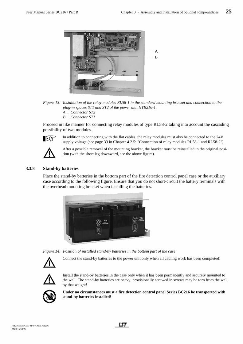
Figure 13: Installation of the relay modules RL58-1 in the standard mounting bracket and connection to theplug-in spaces ST1 and ST2 of the power unit NTB216-1.A ... Connector ST2B ... Connector ST1
Proceed in like manner for connecting relay modules of type RL58-2 taking into account the cascadingpossibility of two modules.
In addition to connecting with the flat cables, the relay modules must also be connected to the 24Vsupply voltage (see page 33 in Chapter 4.2.5: "Connection of relay modules RL58-1 and RL58-2").
After a possible removal of the mounting bracket, the bracket must be reinstalled in the original posi-tion (with the short leg downward, see the above figure).
3.3.8 Stand-by batteries
Place the stand-by batteries in the bottom part of the fire detection control panel case or the auxiliarycase according to the following figure. Ensure that you do not short-circuit the battery terminals withthe overhead mounting bracket when installing the batteries.
Figure 14: Position of installed stand-by batteries in the bottom part of the case
Connect the stand-by batteries to the power unit only when all cabling work has been completed!
Install the stand-by batteries in the case only when it has been permanently and securely mounted tothe wall. The stand-by batteries are heavy, provisionally screwed in screws may be torn from the wallby that weight!
Under no circumstances must a fire detection control panel Series BC216 be transported withstand-by batteries installed!
HB216BE.SAM / 0140 / AN9161206 ZN5015/59/25
User Manual Series BC216 / Part B Chapter 3 • Assembly and installation of optional componentries 25

3.4 Installation of the auxiliary case GEH216-4
The same instructions apply for the installation and the place of assembly of the auxiliary caseGEH216-4 as for the control panel (see from page 17 in Chapter 3.1: "Place of assembly" and frompage 18 in Chapter 3.2: "Panel installation"). Basically you should install the auxiliary case to the leftor to the right of the control panel case in direct vicinity. It is ensured only then that
the cables connecting the two cases are protected sufficiently against EMC and mechanical influ-ences andthe temperature conditions inside the two cases are approximately equal.
In order to refer to the two cases as "fire detection control panel", the control panel Series BC216 caseand the auxiliary case GEH216-4 must be installed directly to one another.
3.4.1 Installation of the stand-by batteries
The same instructions and hints apply for the installation of the stand-by batteries in the auxiliary caseGEH216-4 as for the installation in the control panel (see from page 25 in Chapter 3.3.8: "Stand-bybatteries").
If you intend to install more than one battery set (consisting of 2 batteries of 12V/17Ah, max. 20Ah) inthe auxiliary case GEH216-4 you have to install a battery bracket BK216-1, corresponding to the fol-lowing figure. The assembly material necessary is enclosed to the battery bracket.
Figure 15: Auxiliary case GEH216-4 with installed battery bracket BK216-1
An auxiliary case GEH216-4 may under no circumstances be transported with stand-by batter-ies installed!
3.4.2 Installation of mounting brackets BW216-1
Thread bolts are arranged on the case bottom part to which up to 4 optional mounting brackets for addi-tional componentries (mounting brackets BW216-1) can be installed, corresponding to the followingfigure. The assembly material necessary is enclosed to every mounting bracket BW216-1.
Is a battery bracket already installed in the auxiliary case GEH216-4, only 1 mounting bracketBW216-1 can be installed additionally.
=8/$6681
*
HB216BE.SAM / 0140 / AN9161206ZN5015/59/26
26 Chapter 3 • Assembly and installation of optional componentries User Manual Series BC216 / Part B
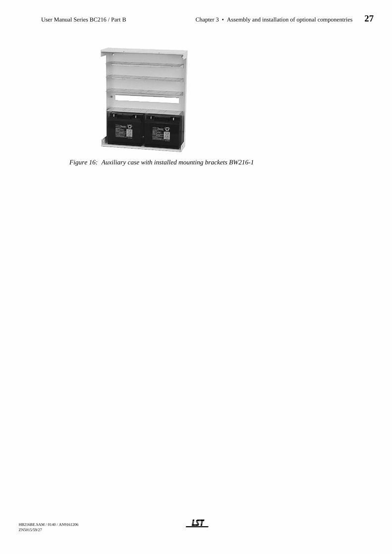
Figure 16: Auxiliary case with installed mounting brackets BW216-1
HB216BE.SAM / 0140 / AN9161206 ZN5015/59/27
User Manual Series BC216 / Part B Chapter 3 • Assembly and installation of optional componentries 27
4 Connection
This chapter generally describes the connection of the usual components of a fire detection system tothe fire detection control panel Series BC216. With the network fire detection control panel BCnet216the connection hints are analogously valid for all BCnet sectional control panels.
Detailed connection and terminal assignment of detectors, signalling devices, transmitting devices, op-erating and display facilities, etc., are described in the respective equipment descriptions.
4.1 General instructions
The conductor cross section of the connection cables to the external components must be chosen as afunction of the power consumption of the connected components and the length of the cables. In di-mensioning the wires, pay special attention to the voltage drops on the connection cables of the signal-ling devices! To ensure adequate strength, adhere to the minimum core diameter of 0.6mm for theconnection of external components.
If the number of connection terminals for the 24V supply of the external devices is inadequate, addi-tional distribution terminals must be installed. On no account should several wires be connected to oneterminal.
The wires must be pull-relieved in the control panel. A stamped bracket in the cable inlet area to whichcables can be secured by means of cable straps serves this purpose.
If shielded cables are used for the installation, the shielding wires must be connected with the controlpanel case on one side. Terminal connections are provided for this purpose in the control panel casebottom part. The bare shielding wires must be insulated (e.g., by covering with an insulating tube) sothat they cannot cause any short circuits. The shielding wires of an interrupted wiring (e.g., with a de-tector base) must be safely connected to avoid earth leakage at this point. In order to avoid inductionloops, the shielding wire of one end of a circular wiring installation must only be connected to one ofthe earth connections of the control panel case (e.g., only at the beginning of the ring line), and theshielding wire of the other end of the ring line must be insulated.
Observe the installation regulations for fire alarm systems and the regulations for electrical installa-tions! Connect the local equipotential connection carefully to the screw connection installed in the casebottom part to ensure that the protective measures are fully effective.
If you have dislocated components of the control panel (e.g., relay modules, other switching devices,batteries, etc.) to an auxiliary case, all protective measures (connection to protective earth, equipoten-tial connection, etc.) must also be taken for the auxiliary case.
Ensure safe separation of the mains power wiring and the 24V low voltage lines.
Before starting any installation work, commissioning or maintenance, all actuation devices which mayautomatically be activated by the fire detection control panel (e.g., extinguishing systems) must be re-liably taken out of service. Unintended activation of actuations may endanger human life or result inmajor damage to property. Establish contact with the responsible person (e.g., fire prevention officer,safety representative) to have the necessary mechanical or electrical switch-offs carried out.
All additional materials required for the installation, connection and commissioning are included in thepackage accompanying the fire detection control panel and the optional componentries. Keep the left-over material in the control panel case. This remaining material may come in handy for possible ex-pansions or modifications.
Consider that with the network fire detection control panel BCnet216 the single GSSnet members arenot galvanically interconnected but are completely electrically isolated from each other!
The components of the EMC protection circuits of the inputs and outputs are not shown in the follow-ing connection diagrams to improve clarity.
HB216BE.SAM / 0140 / AN9161206ZN5015/59/28
28 Chapter 4 • Connection User Manual Series BC216 / Part B
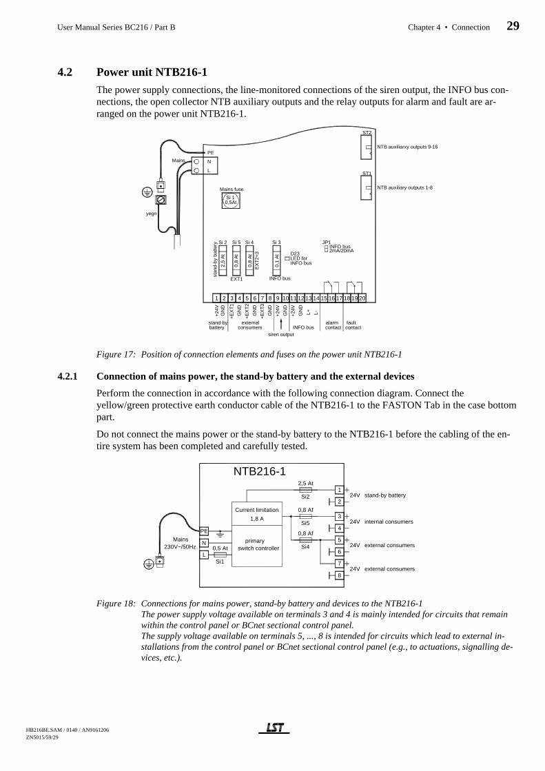
4.2 Power unit NTB216-1
The power supply connections, the line-monitored connections of the siren output, the INFO bus con-nections, the open collector NTB auxiliary outputs and the relay outputs for alarm and fault are ar-ranged on the power unit NTB216-1.
Figure 17: Position of connection elements and fuses on the power unit NTB216-1
4.2.1 Connection of mains power, the stand-by battery and the external devices
Perform the connection in accordance with the following connection diagram. Connect theyellow/green protective earth conductor cable of the NTB216-1 to the FASTON Tab in the case bottompart.
Do not connect the mains power or the stand-by battery to the NTB216-1 before the cabling of the en-tire system has been completed and carefully tested.
Figure 18: Connections for mains power, stand-by battery and devices to the NTB216-1 The power supply voltage available on terminals 3 and 4 is mainly intended for circuits that remainwithin the control panel or BCnet sectional control panel.The supply voltage available on terminals 5, ..., 8 is intended for circuits which lead to external in-stallations from the control panel or BCnet sectional control panel (e.g., to actuations, signalling de-vices, etc.).
PE
N
L
Si 10,5At
Si 2 Si 5 Si 4 Si 3
2,5
At
0,8
At
0,8
At
0,1
At
ST1
ST2
JP1
+24V
GN
D
stand-by
+EX
T1
GN
D
+EX
T2
GN
D
+EX
T3
GN
D
externalconsumers
+24V
GN
D
L+ L-
INFO bus
+24V
GN
D
siren output
alarm fault
Mains
NTB auxiliary outputs 1-8
NTB auxiliarxy outputs 9-16
contact contact
stan
d-by
bat
tery
Mains fuse
EXT1
EX
T2+
3
INFO bus
LED forINFO bus
INFO bus2mA/20mA
battery
yegn
1 2 3 4 5 6 7 8 9 10 11 12 13 14 15 16 17 18 19 20
D23
1
2
3
4
5
6
7
8
L
N
PE
0,5 At
0,8 Af
0,8 Af
2,5 At
primaryswitch controller
Current limitation
1,8 A
stand-by battery
external consumers
external consumers
internal consumers
Mains230V~/50Hz
24V
24V
24V
24V
NTB216-1
Si1
Si2
Si5
Si4
HB216BE.SAM / 0140 / AN9161206 ZN5015/59/29
User Manual Series BC216 / Part B Chapter 4 • Connection 29

The primary switch controller on the power unit NTB216-1 is protected by a metal covering hood. Onno account should you remove this cover, as this would expose components carrying dangerous volt-ages. The module must neither be operated with mains voltage with the NTB216-1 removed from thecontrol panel case since the high voltages are also accessible on the printed circuit board lower sideand the protective earth connection is interrupted.
The mains voltage must be supplied by way of a separately fuse-protected and marked mains powercircuit. No devices other than those belonging to the fire detection system must be connected to thiscircuit.
The cables for the connection of the stand-by battery set to the power unit NTB216-1 are included inthe package accompanying the control panel. Use the red cable as positive connection and the black ca-ble as negative connection.If the stand-by battery is accommodated outside the control panel case (e.g., in an auxiliary caseGEH216-4), at least cables of identical quality must be used for connecting.
Lay the cables inside or outside the control panel case in a way that no damage to the cable insulationcan occur by sharp edges and fix the cable in the desired position (e.g., by means of cable binders, ca-ble channels, etc.).
It is indispensable to ensure the correct polarity (red = "+", black = "-") when connecting the stand-bybattery! Incorrect polarity causes considerable damage to the control panel!
If two stand-by battery sets have to be connected in parallel you require two additional connection ca-bles and one link cable according to the original equipment. Use distribution terminals for connectingthe two battery sets since only one connection cable each may be connected to the connection terminalsfor the stand-by battery of the NTB216-1 (terminals 1 and 2).
Under no circumstances the stand-by batteries or the consumer currents of different BCnet sectionalcontrol panels may be connected in parallel! The low-voltage side of the power supply of every BCnetsectional control panel must always be working separately without being connected to a further BCnetsectional control panel.
Two fuse-protected electrical circuits are available for the power supply of additionally connected de-vices (e.g., relay modules, signalling devices, etc.). It is recommended
to connect the electrical circuits remaining in the control panel or BCnet sectional control panel toterminals 3(+) and 4(-) and,to connect the electrical circuits leading out of the control panel or BCnet sectional control panel(e.g., for external actuations, signalling devices, etc.) to the terminals 5(+) and 6(-) or the terminals7(+) and 8(-).
This serves to ensure that during a short circuit affecting the circuits leading to the outside, the controlcurrent circuits within the control panel are not affected.
If a transmitting device is used for notifying the fire brigade, which has to be supplied with energyfrom the fire detection control panel, it is recommended to connect this device also to terminals 3(+)and 4(-). However, this line must be carefully installed and protected so that a short circuit on this linecan be safely excluded. This approach serves to ensure that the transmitting device is uncoupled fromthe external installations connected to the terminals 5, ..., 8 and cannot be shut down by a short circuitin the external installation (e.g., through a defective actuation).
The failure of the fuses Si1, Si2, Si4 and Si5 is automatically recognised by the control panel andevaluated as a fault. Reference to the cause of the fault is made on the LC-display of the control panel.
4.2.2 Connection to the siren output
The siren output is primarily designated for the line-monitored activation of acoustic or optic signallingdevices (sirens, flashlights, etc.). Usually this siren output is used as the primary alarming device butyou can set the parameters of this output for other functions (e.g., as actuation, etc.) as well.
=8/$6681
*
HB216BE.SAM / 0140 / AN9161206ZN5015/59/30
30 Chapter 4 • Connection User Manual Series BC216 / Part B

Every alarming device which is connected to the siren output of the NTB216-1 is designated as pri-mary alarming device, provided that the siren output was set as alarming device. The primary alarmingdevice is operated on the control panel with the operating and display elements of the field 'ALARM.DEVICE 1'. This alarming device is preferably constructed as a siren (or several sirens connected inparallel) for warning the endangered persons, but the connection of flashlights or other alarming de-vices is also possible.
Figure 19: Connection of signalling devices to the siren outputThe maximum permissible continuous load of the output is 150mA.If signal elements are employed which are already equipped with an incorrect polarity protection di-ode, the diodes drawn in the diagram are not required.Use 1N4004 or similar diodes.
Basically the parameters of the siren output of the NTB216-1 can be set freely. Therefore you can setthis output also as actuation, transmitting device, etc. (see User Manual / Part C). The operating anddisplaying elements in the field 'ALARM. DEVICE 1' are only effective when the siren output was setas alarming device!
At a failure of the central computer of a fire detection control panel BC216-1 or of a BCnet sectionalcontrol panel BC216-2 the siren output will always be activated in case of alarm - independent fromwhich functions its parameters were set for (see from page 39 in Chapter 4.6.2.1: "System fault / re-dundant alarm")!
Line monitoring is effected by a negative monitoring voltage (approximately -1.2V at 5.6kΩ end of lineresistor) available on terminal 9 in normal condition. The drawn diodes block this negative voltage ateach signalling device. In the event of an alarm the full supply voltage (+24V) is available current-limited and short-circuit proof on terminal 9.
The current limitation of this output operates dynamically: When the limit value is exceeded, the limi-tation switches off the output and thereafter attempts at short intervals to again switch on the outputvoltage.
Should several signalling devices be operated monitored on the siren output, they have to be connectedin a chain similar to conventional detectors as shown in figure 19. With radial cabling, display of a lineinterruption is only possible for that part of the cable equipped with the end of line resistor. Pleasenote the limited current capacity of this monitored output.Under no circumstances the siren outputs of BCnet sectional control panels may be connected inparallel!
If no device is connected to the siren output, terminals 9 and 10 have to be closed with a 5.6kΩ resistorinstead or set as "not defined" (see User Manual / Part C) to prevent that a fault is displayed on the con-trol panel.
Resistors 5.6kΩ and diodes 1N4004 are included in the package accompanying the control panel
The colour code for a resistor with 5.6kΩ consists of the colour rings green-blue-red and the colourring for the tolerance (e.g., gold = 5 %).
4.2.3 Connection of the INFO bus
Up to 8 signalling and display devices (e.g., fire brigade control units, fire brigade display facilities,signalling devices, remote indication units, etc.) can be coupled to the fire detection control panel
9
10N TB216-1
a la rm siren sline-m onito re d
siren o utput R5 ,6k
=
24 V
IN 4 004
HB216BE.SAM / 0140 / AN9161206 ZN5015/59/31
User Manual Series BC216 / Part B Chapter 4 • Connection 31
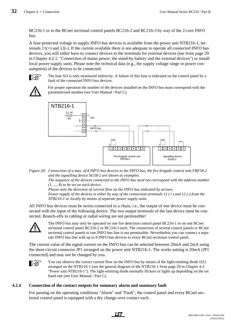
BC216-1 or to the BCnet sectional control panels BC216-2 and BC216-3 by way of the 2-core INFObus.
A fuse-protected voltage to supply INFO bus devices is available from the power unit NTB216-1, ter-minals 11(+) and 12(-). If the current available there is not adequate to operate all connected INFO busdevices, you will either have to connect devices to the terminals for external devices (see from page 29in Chapter 4.2.1: "Connection of mains power, the stand-by battery and the external devices") or installlocal power supply units. Please note the technical data (e.g., the supply voltage range or power con-sumption) of the devices to be connected.
The fuse Si3 is only monitored indirectly: A failure of this fuse is indicated on the control panel by afault of the connected INFO bus devices.
For proper operation the number of the devices installed on the INFO bus must correspond with theparameterised number (see User Manual / Part C).
Figure 20: Connection of a max. of 8 INFO bus devices to the INFO bus, the fire brigade control unit FBF58-2and the signalling device SG58-2 are shown as examples.The sequence of the devices connected to the INFO bus need not correspond with the address number(1, ..., 8) to be set on each device.Please note the direction of current flow on the INFO bus indicated by arrows.Power supply of the devices is either by way of the connection terminals 11 (+) and 12 (-) from theNTB216-1 or locally by means of separate power supply units.
All INFO bus devices must be series-connected in a chain, i.e., the output of one device must be con-nected with the input of the following device. The two output terminals of the last device must be con-nected. Branch-offs in cabling or radial wiring are not permissible!
The INFO bus may only be operated on one fire detection control panel BC216-1 or on one BCnetsectional control panel BC216-2 or BC216-3 each. The connection of several control panels or BCnetsectional control panels to one INFO bus line is not permissible. Nevertheless you can connect a sepa-rate INFO bus line with up to 8 INFO bus devices to every BCnet sectional control panel.
The current value of the signal current on the INFO bus can be selected between 20mA and 2mA usingthe short-circuit connector JP1 arranged on the power unit NTB216-1. The works setting is 20mA (JP1connected) and may not be changed by you.
You can observe the correct current flow on the INFO bus by means of the light-emitting diode D23arranged on the NTB216-1 (see the general diagram of the NTB216-1 from page 29 in Chapter 4.2:"Power unit NTB216-1"). The light-emitting diode normally flickers or lights up depending on the setbaud rate (see User Manual / Part C).
4.2.4 Connection of the contact outputs for summary alarm and summary fault
For passing on the operating conditions "Alarm" and "Fault", the control panel and every BCnet sec-tional control panel is equipped with a dry change-over contact each.
11
12
14
13
0,1 Af
NTB216-1
INFO bus
24V
1 2 3 4 5 6 7 8
24V
Fire brigade control unitFBF58-2
1 532 4 6
signalling deviceSG58-2
Si3
24V
HB216BE.SAM / 0140 / AN9161206ZN5015/59/32
32 Chapter 4 • Connection User Manual Series BC216 / Part B

Figure 21: Connection of the dry contact outputs for summary alarm and summary fault.The relay contacts are shown with the relays in the de-energised state. With the control panel in nor-mal condition, the fault relay is activated and the alarm relay is released.
4.2.5 Connection of relay modules RL58-1 and RL58-2
16 auxiliary outputs with free to set parameters (NTB outputs) on the power unit NTB216-1 are con-nected to two 10-pin flat cable connectors ST1 and ST2 to which the relay modules of type RL58-1 andRL58-2 can be connected.
Figure 22 Connection of relay modules RL58-1 and RL58-2 to the auxiliary outputs (NTB outputs) of the powerunit NTB216-1.The supply voltage is not supplied via the flat cable connection, which is why you have to additionallyconnect the relay modules to the terminals for internal control panel devices (i.e., to terminals 3, 4 ofthe NTB216-1, see from page 29 in Chapter 4.2.1: "Connection of mains power, the stand-by batteryand the external devices").The figure is an example, you can connect either a relay module RL58-1 or two relay modules RL58-2to each of the two flat cable connectors ST1 or ST2 of the power unit NTB216-1.
The supply voltage for the relay modules is not supplied via the flat cable connection, it must be sup-plied separately. To do so, use the voltage available on terminals 3 and 4 of the power unit NTB216-1for internal control panel devices (see from page 29 in Chapter 4.2.1: "Connection of mains power, thestand-by battery and the external devices").
The outputs on ST1 or ST2 are only suitable for the connection of relay modules of types RL58-1 andRL58-2 or similar. On no account must wiring connected to these outputs be led out of the fire detec-tion control panel case or the optional auxiliary case, installed directly beside the control panel case!
The flat cables required for connecting the relay modules to the NTB216-1 are enclosed with the relaymodules. If the relay modules are installed in the auxiliary case you have to either convert the flat ca-ble connectors ST1 or ST2 on the NTB216-1 to terminals (e.g., by using the plug converter boardSUB58-2) and separately wire the relay modules or you have to use longer flat cables.
Do not connect relay modules and similar devices to a supply voltage which may be affected by ashort-circuit in the wiring outside the control panel!
15
16
17
18
19
20
NTB216-1alarmmax. 60V/1A/30W
faultmax. 60V/1A/30W
ST2
ST1
NTB216-1
ST1
RL58-110
1
RL58-2
1
6
ST1
NTB outputs 1...8
24V
24V
NTB outputs 9...16
ST2
24V6
1
RL58-2
ST2
ST1
HB216BE.SAM / 0140 / AN9161206 ZN5015/59/33
User Manual Series BC216 / Part B Chapter 4 • Connection 33
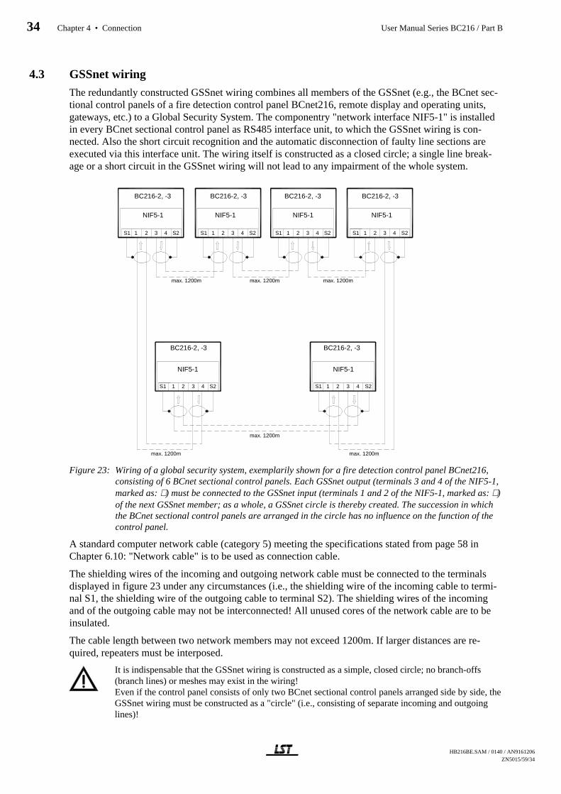
4.3 GSSnet wiring
The redundantly constructed GSSnet wiring combines all members of the GSSnet (e.g., the BCnet sec-tional control panels of a fire detection control panel BCnet216, remote display and operating units,gateways, etc.) to a Global Security System. The componentry "network interface NIF5-1" is installedin every BCnet sectional control panel as RS485 interface unit, to which the GSSnet wiring is con-nected. Also the short circuit recognition and the automatic disconnection of faulty line sections areexecuted via this interface unit. The wiring itself is constructed as a closed circle; a single line break-age or a short circuit in the GSSnet wiring will not lead to any impairment of the whole system.
Figure 23: Wiring of a global security system, exemplarily shown for a fire detection control panel BCnet216,consisting of 6 BCnet sectional control panels. Each GSSnet output (terminals 3 and 4 of the NIF5-1,marked as: ⇓ ) must be connected to the GSSnet input (terminals 1 and 2 of the NIF5-1, marked as: ⇑ )of the next GSSnet member; as a whole, a GSSnet circle is thereby created. The succession in whichthe BCnet sectional control panels are arranged in the circle has no influence on the function of thecontrol panel.
A standard computer network cable (category 5) meeting the specifications stated from page 58 inChapter 6.10: "Network cable" is to be used as connection cable.
The shielding wires of the incoming and outgoing network cable must be connected to the terminalsdisplayed in figure 23 under any circumstances (i.e., the shielding wire of the incoming cable to termi-nal S1, the shielding wire of the outgoing cable to terminal S2). The shielding wires of the incomingand of the outgoing cable may not be interconnected! All unused cores of the network cable are to beinsulated.
The cable length between two network members may not exceed 1200m. If larger distances are re-quired, repeaters must be interposed.
It is indispensable that the GSSnet wiring is constructed as a simple, closed circle; no branch-offs(branch lines) or meshes may exist in the wiring!Even if the control panel consists of only two BCnet sectional control panels arranged side by side, theGSSnet wiring must be constructed as a "circle" (i.e., consisting of separate incoming and outgoinglines)!
BC216-2, -3 BC216-2, -3 BC216-2, -3 BC216-2, -3
BC216-2, -3 BC216-2, -3
NIF5-1 NIF5-1 NIF5-1 NIF5-1
NIF5-1 NIF5-1
max. 1200m max. 1200m max. 1200m
max. 1200m
max. 1200m max. 1200m
S1 1 32 4 S2
S1 1 2 3 4 S2
S1 1 2 3 4 S2 S1 1 2 3 4 S2 S1 1 2 3 4 S2
S1 1 2 3 4 S2
HB216BE.SAM / 0140 / AN9161206ZN5015/59/34
34 Chapter 4 • Connection User Manual Series BC216 / Part B
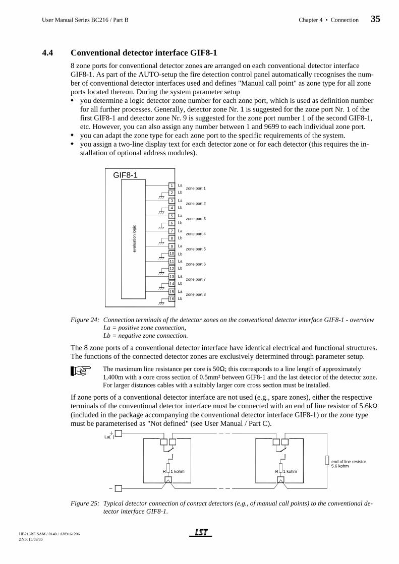
4.4 Conventional detector interface GIF8-1
8 zone ports for conventional detector zones are arranged on each conventional detector interfaceGIF8-1. As part of the AUTO-setup the fire detection control panel automatically recognises the num-ber of conventional detector interfaces used and defines "Manual call point" as zone type for all zoneports located thereon. During the system parameter setup
you determine a logic detector zone number for each zone port, which is used as definition numberfor all further processes. Generally, detector zone Nr. 1 is suggested for the zone port Nr. 1 of thefirst GIF8-1 and detector zone Nr. 9 is suggested for the zone port number 1 of the second GIF8-1,etc. However, you can also assign any number between 1 and 9699 to each individual zone port.you can adapt the zone type for each zone port to the specific requirements of the system.you assign a two-line display text for each detector zone or for each detector (this requires the in-stallation of optional address modules).
Figure 24: Connection terminals of the detector zones on the conventional detector interface GIF8-1 - overviewLa = positive zone connection, Lb = negative zone connection.
The 8 zone ports of a conventional detector interface have identical electrical and functional structures.The functions of the connected detector zones are exclusively determined through parameter setup.
The maximum line resistance per core is 50Ω; this corresponds to a line length of approximately1,400m with a core cross section of 0.5mm² between GIF8-1 and the last detector of the detector zone.For larger distances cables with a suitably larger core cross section must be installed.
If zone ports of a conventional detector interface are not used (e.g., spare zones), either the respectiveterminals of the conventional detector interface must be connected with an end of line resistor of 5.6kΩ(included in the package accompanying the conventional detector interface GIF8-1) or the zone typemust be parameterised as "Not defined" (see User Manual / Part C).
Figure 25: Typical detector connection of contact detectors (e.g., of manual call points) to the conventional de-tector interface GIF8-1.
2
3
1
6
4
5
9
8
7
10
11
12
16
15
14
13
La
Lbzone port 1
zone port 2Lb
La
zone port 3Lb
La
zone port 4Lb
La
zone port 5Lb
La
zone port 6Lb
La
zone port 7Lb
La
zone port 8Lb
La
GIF8-1
eval
uatio
n lo
gic
R
end of line resistor5.6 kohm
La( )
1 kohm 1 kohmR
HB216BE.SAM / 0140 / AN9161206 ZN5015/59/35
User Manual Series BC216 / Part B Chapter 4 • Connection 35
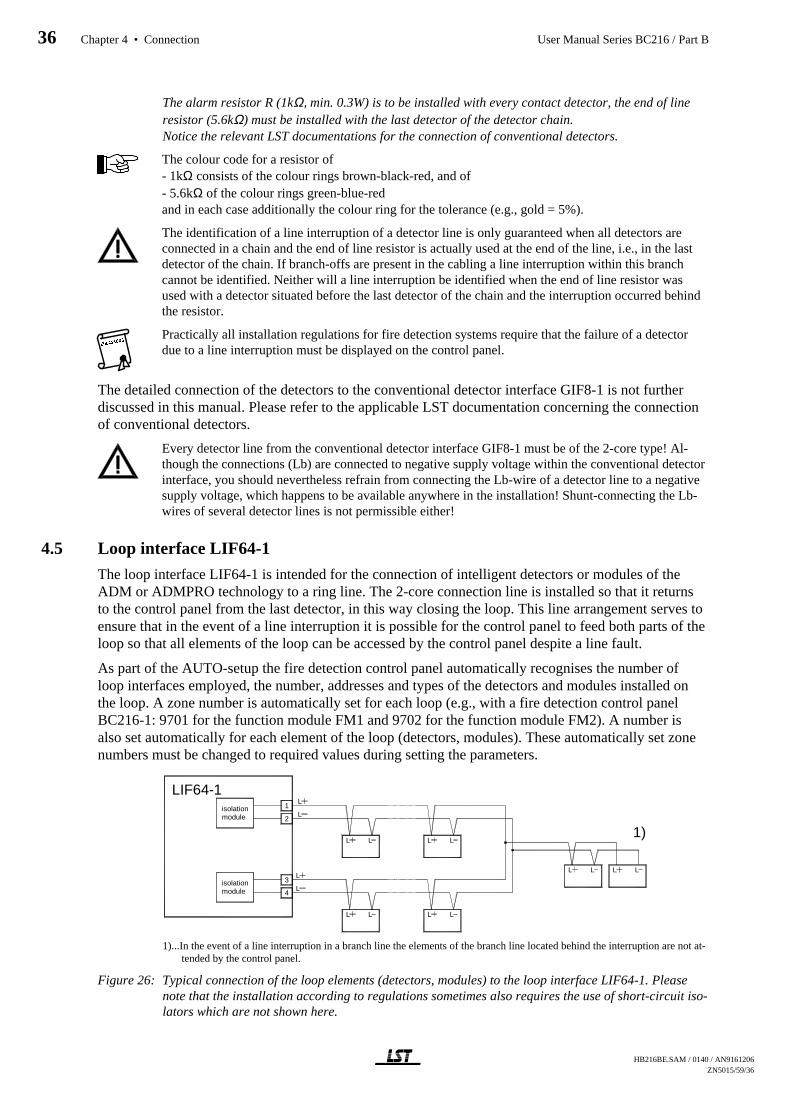
The alarm resistor R (1kΩ, min. 0.3W) is to be installed with every contact detector, the end of lineresistor (5.6kΩ) must be installed with the last detector of the detector chain.Notice the relevant LST documentations for the connection of conventional detectors.
The colour code for a resistor of- 1kΩ consists of the colour rings brown-black-red, and of- 5.6kΩ of the colour rings green-blue-redand in each case additionally the colour ring for the tolerance (e.g., gold = 5%).
The identification of a line interruption of a detector line is only guaranteed when all detectors areconnected in a chain and the end of line resistor is actually used at the end of the line, i.e., in the lastdetector of the chain. If branch-offs are present in the cabling a line interruption within this branchcannot be identified. Neither will a line interruption be identified when the end of line resistor wasused with a detector situated before the last detector of the chain and the interruption occurred behindthe resistor.
Practically all installation regulations for fire detection systems require that the failure of a detectordue to a line interruption must be displayed on the control panel.
The detailed connection of the detectors to the conventional detector interface GIF8-1 is not furtherdiscussed in this manual. Please refer to the applicable LST documentation concerning the connectionof conventional detectors.
Every detector line from the conventional detector interface GIF8-1 must be of the 2-core type! Al-though the connections (Lb) are connected to negative supply voltage within the conventional detectorinterface, you should nevertheless refrain from connecting the Lb-wire of a detector line to a negativesupply voltage, which happens to be available anywhere in the installation! Shunt-connecting the Lb-wires of several detector lines is not permissible either!
4.5 Loop interface LIF64-1
The loop interface LIF64-1 is intended for the connection of intelligent detectors or modules of theADM or ADMPRO technology to a ring line. The 2-core connection line is installed so that it returnsto the control panel from the last detector, in this way closing the loop. This line arrangement serves toensure that in the event of a line interruption it is possible for the control panel to feed both parts of theloop so that all elements of the loop can be accessed by the control panel despite a line fault.
As part of the AUTO-setup the fire detection control panel automatically recognises the number ofloop interfaces employed, the number, addresses and types of the detectors and modules installed onthe loop. A zone number is automatically set for each loop (e.g., with a fire detection control panelBC216-1: 9701 for the function module FM1 and 9702 for the function module FM2). A number isalso set automatically for each element of the loop (detectors, modules). These automatically set zonenumbers must be changed to required values during setting the parameters.
1)...In the event of a line interruption in a branch line the elements of the branch line located behind the interruption are not at-tended by the control panel.
Figure 26: Typical connection of the loop elements (detectors, modules) to the loop interface LIF64-1. Pleasenote that the installation according to regulations sometimes also requires the use of short-circuit iso-lators which are not shown here.
=8/$6681
*
2
3
1
4
L
L
LIF64-1isolationmodule
isolationmodule
1)L L LL
LL LL
LLLL
L
L
HB216BE.SAM / 0140 / AN9161206ZN5015/59/36
36 Chapter 4 • Connection User Manual Series BC216 / Part B
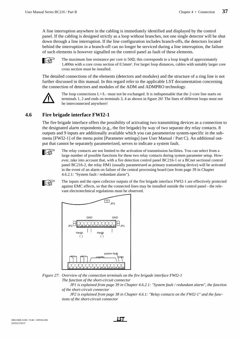
A line interruption anywhere in the cabling is immediately identified and displayed by the controlpanel. If the cabling is designed strictly as a loop without branches, not one single detector will be shutdown through a line interruption. If the line configuration includes branch-offs, the detectors locatedbehind the interruption in a branch-off can no longer be serviced during a line interruption, the failureof such elements is however signalled on the control panel as fault of these elements.
The maximum line resistance per core is 50Ω; this corresponds to a loop length of approximately1,400m with a core cross section of 0.5mm². For larger loop distances, cables with suitably larger corecross section must be installed.
The detailed connections of the elements (detectors and modules) and the structure of a ring line is notfurther discussed in this manual. In this regard refer to the applicable LST documentation concerningthe connection of detectors and modules of the ADM and ADMPRO technology.
The loop connections L+/L- must not be exchanged. It is indispensable that the 2-core line starts onterminals 1, 2 and ends on terminals 3, 4 as shown in figure 26! The lines of different loops must notbe interconnected anywhere!
4.6 Fire brigade interface FWI2-1
The fire brigade interface offers the possibility of activating two transmitting devices as a connection tothe designated alarm respondents (e.g., the fire brigade) by way of two separate dry relay contacts. 8outputs and 9 inputs are additionally available which you can parameterize system-specific in the sub-menu [FWI2-1] of the menu point [Parameter settings] (see User Manual / Part C). An additional out-put that cannot be separately parameterized, serves to indicate a system fault.
The relay contacts are not limited to the activation of transmission facilities. You can select from alarge number of possible functions for these two relay contacts during system parameter setup. How-ever, take into account that, with a fire detection control panel BC216-1 or a BCnet sectional controlpanel BC216-2, the relay HM1 (usually parametrized as primary transmitting device) will be activatedin the event of an alarm on failure of the central processing board (see from page 39 in Chapter4.6.2.1: "System fault / redundant alarm").
The inputs and the open collector outputs of the fire brigade interface FWI2-1 are effectively protectedagainst EMC effects, so that the connected lines may be installed outside the control panel - the rele-vant electrotechnical regulations must be observed.
Figure 27: Overview of the connection terminals on the fire brigade interface FWI2-1The function of the short-circuit connector
JP1 is explained from page 39 in Chapter 4.6.2.1: "System fault / redundant alarm", the functionof the short-circuit connector
JP2 is explained from page 38 in Chapter 4.6.1: "Relay contacts on the FWI2-1" and the func-tions of the short-circuit connector
17 18 19 20 21 22 23 24 25 26 27
1 2 3 4 5 6 7 8 9 10 11 12 13 14 15 16
JP2 JP1
HM1 HM2 outputssystem fault
GND
GND GND
inputsinputs( ) ( )
JP3
HB216BE.SAM / 0140 / AN9161206 ZN5015/59/37
User Manual Series BC216 / Part B Chapter 4 • Connection 37

JP3 is explained from page 45 in Chapter 4.8.1.3: "Connection of the BCnet redundant alarmline".
4.6.1 Relay contacts on the FWI2-1
The two relays placed on the FWI2-1 are primarily intended to accomplish the dry activation of trans-mitting devices. If no such activations are required, these relay contacts can be used for any other task(e.g., actuations, etc.).
Figure 28: Connection of the contacts of the relays HM1 and HM2 on the fire brigade interface FWI2-1.The relay contacts are shown in the deactivated (=de-energised) state of the relays. During parameter setup the HM1 relay is referred to as "relay output 1" and the HM2 as "relay out-put 2".
As part of the AUTO-setup the fire detection control panel recognises that a fire brigade interfaceFWI2-1 has been installed and automatically defines the contact of the HM1 relay for activation of theprimary transmitting device.
The primary transmitting device can be operated directly on the control panel keypad (field"TRANSM. DEVICE 1"). The use of the alarm delay procedure is possible for this transmitting deviceonly.
The HM2 relay is not dealt with during AUTO-setup.
You can change this allocation during system parameter setup and assign a different transmitting de-vice or a totally different task to the selected relay. You can also change type and characteristic of thetransmitting devices or establish combinations with detector zones. In addition you can allocate a 2-linetext as designation for the transmitting devices.
If the fire detection control panel is to monitor the line to the transmitting device the use of the fire bri-gade interface additional board FWZ2-1 is required in addition to the fire brigade interface FWI2-1(see from page 20 in Chapter 3.3.3: "Fire brigade interface additional board FWZ2-1" and from page41 in Chapter 4.7: "Fire brigade interface additional board FWZ2-1").
A total of up to 10 transmitting devices can be defined with the fire detection control panel BC216-1or with every BCnet sectional control panel of the fire detection control panel BCnet216. The totalnumber of transmitting devices defined in a network fire detection control panel BCnet216 is limitedto 99.Besides the above mentioned relays on the fire brigade interface FWI2-1 it is also possible to utilisethe open collector outputs of the FWI2-1 and the auxiliary outputs (NTB outputs) of the power unitNTB216-1 for this task.
The HM1 relay has yet another special function: Upon failure of the central processing boardZTB216-1 the HM1 relay (usually parameterized as the primary transmitting device) will be activatedin addition to the other display installations in the event of an alarm ("redundant alarm"). If the short-circuit connector JP2 is connected (see the overview figure from page 37 in Chapter 4.6: "Fire brigadeinterface FWI2-1") the HM2 relay will also be additionally activated in the event of "redundant alarm".
4.6.2 Open collector outputs of the FWI2-1
8 of the 9 available open collector outputs of the fire brigade interface FWI2-1 can be individuallyparameterised site-specific during system parameter setup. The outputs are primarily intended for theconnection of standardised auxiliary components of the fire detection system (e.g., relay modules, fire
FWI2-12
3
1
relay output 24
6
5 max. 60V/1A/30W
HM1
HM2
relay output 1max. 60V/1A/30W
HB216BE.SAM / 0140 / AN9161206ZN5015/59/38
38 Chapter 4 • Connection User Manual Series BC216 / Part B
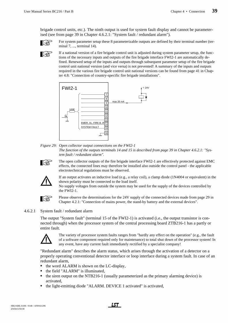
brigade control units, etc.). The ninth output is used for system fault display and cannot be parameter-ised (see from page 39 in Chapter 4.6.2.1: "System fault / redundant alarm").
For system parameter setup these 8 parameterizable outputs are defined by their terminal number (ter-minal 7, ..., terminal 14).
If a national version of a fire brigade control unit is adjusted during system parameter setup, the func-tions of the necessary inputs and outputs of the fire brigade interface FWI2-1 are automatically de-fined. Renewed setup of the inputs and outputs through subsequent parameter setup of the fire brigadecontrol unit national version (and vice versa) is not prevented! A summary of the inputs and outputsrequired in the various fire brigade control unit national versions can be found from page 41 in Chap-ter 4.8: "Connection of country-specific fire brigade installations".
Figure 29: Open collector output connections on the FWI2-1 The function of the outputs terminals 14 and 15 is described from page 39 in Chapter 4.6.2.1: "Sys-tem fault / redundant alarm".
The open collector outputs of the fire brigade interface FWI2-1 are effectively protected against EMCeffects, the connected lines may therefore be installed also outside the control panel - the applicableelectrotechnical regulations must be observed.
If an output activates an inductive load (e.g., a relay coil), a clamp diode (1N4004 or equivalent) in theshown polarity must be connected to the load itself.No supply voltages from outside the system may be used for the supply of the devices controlled bythe FWI2-1.
Please observe the determinations for the 24V supply of the connected devices made from page 29 inChapter 4.2.1: "Connection of mains power, the stand-by battery and the external devices".
4.6.2.1 System fault / redundant alarm
The output "System fault" (terminal 15 of the FWI2-1) is activated (i.e., the output transistor is con-nected through) when the processor system of the central processing board ZTB216-1 has a partly orentire fault.
The variety of processor system faults ranges from "hardly any effect on the operation" (e.g., the faultof a software component required only for maintenance) to total shut down of the processor system! Inany event, have any current fault immediately rectified by a specialist company!
"Redundant alarm" describes the alarm status, which arises through the activation of a detector on aproperly operating conventional detector interface or loop interface during a system fault. In case of anredundant alarm,
the word ALARM is shown on the LC-display,the field "ALARM" is illuminated,the siren output on the NTB216-1 (usually parameterized as the primary alarming device) isactivated,the light-emitting diode "ALARM. DEVICE 1 activated" is activated,
9
8
7
14
15
16
100E10
11
12
13
FWI2-1
SYSTEM FAULT
EMER. AL. FIRE B. IF
24V
max.35 mA
HB216BE.SAM / 0140 / AN9161206 ZN5015/59/39
User Manual Series BC216 / Part B Chapter 4 • Connection 39

the HM1 relay on the fire brigade interface FWI1-2 (usually parameterized as the primary transmit-ting device) is activated (if available),the monitored output of the FWZ2-1 belonging to relay HM1 is activated (if available),the light-emitting diode "TRANSM. DEVICE 1 active" is activated,if JP1 is set on the FWI2-1 the output terminal 14 is activated,if JP2 is set on the FWI2-1, the relay HM2 and the relevant monitored output on the FWZ2-1 isactivated.
Two possibilities can be determined for the output on terminal 14 on the FWI2-1:If the short-circuit connector JP1 on the FWI2-1 is not connected, the output terminal 14 can beparameterised freely.If the short-circuit connector JP1 on the FWI2-1 is connected, the output terminal 14 operates as"redundant alarm". In this case the output type must be set as "Not defined" or "act. on alarm" whenparameterising the output.
The function "alarm delay" is not operational during a redundant alarm.
No redundant alarm is possible at failure of the central computer of a BCnet sectional control panelBC216-3 ("black box" - control panel).
4.6.3 Inputs of the FWI2-1
The 9 available inputs of the fire brigade interface FWI2-1 are preferably intended for the connectionof standardised auxiliary components of the fire detection system (e.g., fire brigade control units, etc.).However, they can also be individually parameterised site-specific.
The inputs of the fire brigade interface FWI2-1 are effectively protected against EMC effects, the con-nected lines can therefore be installed also outside the control panel - observe the applicable electro-technical regulations.
These 9 outputs are defined by their terminal numbers (terminal 17, 18, 19, 21, ..., terminal 26) duringsystem parameter setup.
If a national version of a fire brigade control unit is set during system parameter setup, this automati-cally defines the functions of the inputs and outputs of the fire brigade interface FWI2-1. Renewedsetup of the inputs and outputs through subsequent parameter setup of the national version of the firebrigade control unit (and vice versa) is not prevented! A summary of the inputs and outputs required inthe various fire brigade control unit national versions can be found from page 41 in Chapter 4.8: "Con-nection of country-specific fire brigade installations".
Figure 30: Input connections on the FWI2-1The activation of input terminals 17, 18, 19 is effected by connecting (NO) and disconnecting (NC) ofground.The activation of input terminals 21, ..., 26 is effected by connecting (NO) and disconnecting (NC) apositive voltage.)
21
22
23
24
20
19
18
17
27
25
26
47k
10k
FWI2-1
3 inputs with free to set parameters
6 inputs with free to set parameters
100k
10k
47k
activation with ( )
activation with +24V
24V
HB216BE.SAM / 0140 / AN9161206ZN5015/59/40
40 Chapter 4 • Connection User Manual Series BC216 / Part B

The voltage values permissible for the activation are listed in the specifications from page 96 inChapter 9.5: "Fire brigade interface FWI2-1".
With regard to the inputs activated with +24V, please observe the determinations made from page 29in Chapter 4.2.1: "Connection of mains power, the stand-by battery and the external devices".
4.7 Fire brigade interface additional board FWZ2-1
The fire brigade interface additional board FWZ2-1 plugged onto the fire brigade interface FWI2-1 ex-pands the fire brigade interface by two line-monitored outputs. Functionally, these outputs are shunt-connected with the two relay outputs of the FWI2-1 and have therefore the same functions.
Figure 31: Connections of the fire brigade interface additional board FWZ2-1Both outputs are designed short-circuit proof, the maximum permissible continuous output current foreach output is 150mA.
Line monitoring is effected through a supervising current, the parameters of which can be set in threesteps separately for each output, which continuously flows via the line to be monitored. The approxi-mate values for these steps are: 4mA (=Low), 8mA (=Medium), 12mA (=High). The actual currentflow is dependent on the level of the supply voltage and also on the resistance of the facility to becontrolled.
The internal supply voltage of the control panel is switched to the corresponding output of the FWZ2-1in activated condition (i.e., the relay HM1 or HM2, respectively is picked up on the fire brigade inter-face FWI2-1). The outputs are designed current-limited and short-circuit proof.
The current limitation of the two outputs operates dynamically: On exceeding the threshold value, thelimitation switches off the voltage, subsequently re-attempting in short intervals to switch on the volt-age again.
During AUTO-setup, the fire detection control panel automatically recognises that a fire brigade inter-face additional board has been installed and defines the supervising current for the output connectedwith relay output 1 as "Low". During AUTO-setup, the relay output 2 is set as "Not defined". If the re-lay output 2 is parameterised from "Not defined" to a function, the supervising current of this output isautomatically adjusted to "Low" also. This setting can subsequently be changed for the output type"Transmitting device".
Is the relay HM1 or HM2 used, but the belonging supervised output of the FWZ2-1 is not needed, youhave to connect the terminals of the output with an end of line resistor of 5.6kΩ and set the parametersfor the supervising current to "Low".
4.8 Connection of country-specific fire brigade installations
The inputs and outputs of the fire brigade interface FWI2-1, pre-defined through the parameter setup ofthe fire brigade control unit national version, are identified in the following table.
Terminal,relay
GermanyFBF900-1,2
AustriaFBF58-1
Switzerland
7 (O) FBCU FBCU FBCU8 (O) FBCU FBCU FBCU9 (O) FBCU FBCU
10 (O) FBCU FBCU11 (O) FBCU AD800-1
2
4
3
1
FWZ2-1HM2
HM1 min. 200 ohm
min. 200 ohm
HB216BE.SAM / 0140 / AN9161206 ZN5015/59/41
User Manual Series BC216 / Part B Chapter 4 • Connection 41

Terminal,relay
GermanyFBF900-1,2
AustriaFBF58-1
Switzerland
12 (O) FBCU13 (O) AD70014 (O)17 (I) Transm. dev. 1 AD800-118 (I) FBCU Exting. system19 (I)21 (I) FBCU FBCU FBCU22 (I) FBCU FBCU FBCU23 (I) FBCU FBCU24 (I) FBCU25 (I) FBCU26 (I) AD700HM1 Transm. dev. 1 Transm. dev. 1 Transm. dev. 1HM2 Flashlight Flashlight
Table 1: Overview of the inputs (I) and outputs (O) of the fire brigade interface FWI2-1 used with the fire bri-gade control panel national versions (FBCU) or key safe adapters (ADxxx).
The assigned inputs and outputs are utilised for the activation of the country-specific fire brigade con-trol unit or key safe adapters and are no longer available for general use after the parameter setup of thefire brigade control unit national version. The inputs and outputs not assigned in the above table can beparameterised for any other task.
4.8.1 Connection of the fire brigade installations / Austria
By parameter setup of the fire brigade interface FWI2-1 for the fire brigade control unit national ver-sion Austria the configuration of the inputs and outputs of the FWI2-1 for the connection of the fire bri-gade control unit FBF58-1 and the key safe adapter AD800-1 is set. The connection of the installationsrelevant for the fire brigade to the fire detection control panel Series BC216 is shown in the followingplug charts.
HB216BE.SAM / 0140 / AN9161206ZN5015/59/42
42 Chapter 4 • Connection User Manual Series BC216 / Part B

4.8.1.1 Connection of the fire brigade control unit FBF58-1, the key safe adapter AD800-1 and additionalinstallations.
1)...The light-emitting diode "fire control activated" must be activated by the fire control.3)...If burglar alarm and fault are jointly connected as "sabotage" to the fire brigade interface in the shown manner, the resistor
5.6kΩ on the printed circuit board of the AD800-1 must be removed (see manual AD800-1).4)...The output "burglar alarm" is normally connected to a burglar alarm panel. The output "fault" of the AD800-1 can also be
connected to a GIF8-1 as fault detector. If in this case the AD800-1 is not connected as the last "detector" of the fault de-tector zone, the resistor 5.6kΩ 3) must be removed.
Figure 32: Connection of the fire brigade control unit FBF58-1, the key safe adapter AD800-1 and additional in-stallations to the fire detection control panel Series BC216
5
6
7
8
L
N
PE
0,5 A t
0,8 A f
Prim
ary
switc
hco
ntr.
Cu rren t lim itation
1,8 A
M ains230V~/50Hz
24V
24V
N T B 216-1
Si1
S i4
12
11
13
14
0,1 A f
S i3
21
22
F W I2-1
FB F 58-11
2
ALARM
2k2
2k2
FAU LT, D ISABLEME NT
4
3
5
7
6
ALA RMIN G DEV. R ESET
INTERNA L AC OU STIK R ESET
CON TRO L P ANEL RESET
Re lay output 1
1
3
2
24V100E
100E8
7
47k
10k
47k
10k
47k
10k23
OPER ATION2k2
Controllog ic
yegn
17
Fire contro l activa ted
152k2
2k2Extinguishing system activated
19
21
17
16
15
A la rm
primary TD
Fault
24V
10k
12
5k6
1k
1k
22k
100E
47k
FS S800-1
1
A D 800-1O pera ting voltage
100E10
100E11
10k
47k100k
17
10k
100k18
47k
C onfirma tion
Activation
E x tingu ish ing syst.
C
D
I2
I1
c
24VLa
Lb
Ta
TbIn frane tT N A 10 connection
Telephone
F lash ligh tRelay output 2 5
6
424V
24V
activated
Exting.syst.activated
alarmcond ition
fault cond it./d isablem ent
Exting.syst.activation
Sabotagekey safe
A la rm . dev.reset
Buzzersilence
C ontro l panelreset
primary TDactivated
1)
3 )
4)
4)
20
4
324VS i5
0,8 A f
11
10
12
primary TDactivated
HB216BE.SAM / 0140 / AN9161206 ZN5015/59/43
User Manual Series BC216 / Part B Chapter 4 • Connection 43

4.8.1.2 Connection of the fire brigade control unit FBF58-2, the key safe adapter AD800-1 and additionalinstallations
1)...The light-emitting diode "fire control activated" must be activated by the fire control.2)...The light-emitting diode "extinguishing system activated" must be activated by the extinguishing system3)...If burglar alarm and fault are jointly connected as "sabotage" to the fire brigade interface in the shown manner, the resistor
5.6kΩ on the printed circuit board of the AD800-1 must be removed (see manual AD800-1).4)...The output "burglar alarm" is normally connected to a burglar alarm panel. The output "fault" of the AD800-1 can also be
connected to a GIF8-1 as fault detector. If in this case the AD800-1 is not connected as the last "detector" of the fault detec-tor zone, the resistor 5.6kΩ 3) must be removed.
Figure 33: Connection of the fire brigade control unit FBF58-1, the key safe adapter AD800-1 and additional in-stallations to the fire detection control panel Series BC216
M ains2 30V ~/50H z
24V
24V
20m A -LoopFW I2-1
FB F 58-2
1
2
3
5
7
6
1
3
2
15
16
17
A D 800-1
19
Fa ult
O pera ting vo ltageprim ary TD 24V
yegn
8
24V
10k
2,2k
560
5V
F ire contro lactiva ted
ac tiva tedE xtingu ish ing system
10k
2,2k
5V
560
4
24V
10k
100 k47k
17
10k47k
22k
1 k
connectionT eleph one
In frane tTN A 10
C
D
I2
I1
c
La
Lb
T a
T b
47k
10k
100 k18
111 00E
E xtingu ishing syst.
A ctiva tion
C onfirm ation
5
6
4
24V
F lash ligh t24V
1
12
F SS 80 0-1
211 k100E
5,6k
A larm
E xtin g .syst.activation
S abotage
R ela y o utpu t 1
R ela y o utpu t 2
1 )
2 )
3)
4)
4)
20
N TB 216-1
1,8 A
C urren t lim ita tion
Prim
ary
0 ,5 A tN
LS i1
P E
switc
hco
ntr.
8
C ontro llog ic
0 ,1 Af
S i3
14
13
11
12
S i5
0 ,8 Af
S i4
0 ,8 Af3
4
7
6
5
24V
activated
prim ary TDactivated
prim ary TDactivated
f. brig . ke y box
HB216BE.SAM / 0140 / AN9161206ZN5015/59/44
44 Chapter 4 • Connection User Manual Series BC216 / Part B
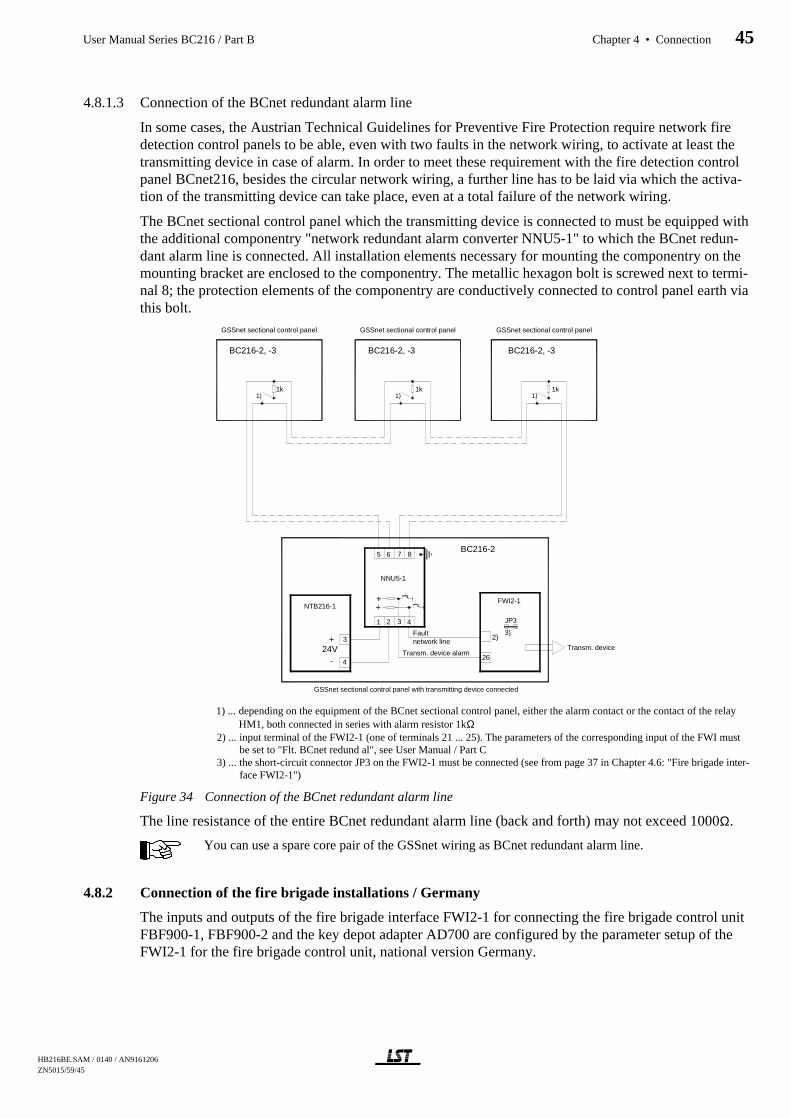
4.8.1.3 Connection of the BCnet redundant alarm line
In some cases, the Austrian Technical Guidelines for Preventive Fire Protection require network firedetection control panels to be able, even with two faults in the network wiring, to activate at least thetransmitting device in case of alarm. In order to meet these requirement with the fire detection controlpanel BCnet216, besides the circular network wiring, a further line has to be laid via which the activa-tion of the transmitting device can take place, even at a total failure of the network wiring.
The BCnet sectional control panel which the transmitting device is connected to must be equipped withthe additional componentry "network redundant alarm converter NNU5-1" to which the BCnet redun-dant alarm line is connected. All installation elements necessary for mounting the componentry on themounting bracket are enclosed to the componentry. The metallic hexagon bolt is screwed next to termi-nal 8; the protection elements of the componentry are conductively connected to control panel earth viathis bolt.
1) ... depending on the equipment of the BCnet sectional control panel, either the alarm contact or the contact of the relayHM1, both connected in series with alarm resistor 1kΩ
2) ... input terminal of the FWI2-1 (one of terminals 21 ... 25). The parameters of the corresponding input of the FWI mustbe set to "Flt. BCnet redund al", see User Manual / Part C
3) ... the short-circuit connector JP3 on the FWI2-1 must be connected (see from page 37 in Chapter 4.6: "Fire brigade inter-face FWI2-1")
Figure 34 Connection of the BCnet redundant alarm line
The line resistance of the entire BCnet redundant alarm line (back and forth) may not exceed 1000Ω.
You can use a spare core pair of the GSSnet wiring as BCnet redundant alarm line.
4.8.2 Connection of the fire brigade installations / Germany
The inputs and outputs of the fire brigade interface FWI2-1 for connecting the fire brigade control unitFBF900-1, FBF900-2 and the key depot adapter AD700 are configured by the parameter setup of theFWI2-1 for the fire brigade control unit, national version Germany.
BC216-2, -3 BC216-2, -3BC216-2, -3
GSSnet sectional control panel GSSnet sectional control panel GSSnet sectional control panel
BC216-2
NNU5-1
FWI2-1
Transm. device
Fault
Transm. device alarm
network line+24V
NTB216-1
-
JP3
3)2)
431 2
765
GSSnet sectional control panel with transmitting device connected
3
426
++
8
1)1k 1k
1)1k
1)
HB216BE.SAM / 0140 / AN9161206 ZN5015/59/45
User Manual Series BC216 / Part B Chapter 4 • Connection 45
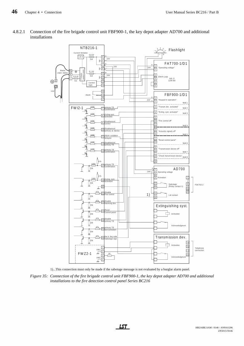
4.8.2.1 Connection of the fire brigade control unit FBF900-1, the key depot adapter AD700 and additionalinstallations
1)...This connection must only be made if the sabotage message is not evaluated by a burglar alarm panel.
Figure 35: Connection of the fire brigade control unit FBF900-1, the key depot adapter AD700 and additionalinstallations to the fire detection control panel Series BC216
5
6
7
8
L
N
PE
0,5 A t
0 ,8 A f
Prim
ary
switc
hco
ntr.
Cu rrent lim ita ton
1 ,8 A
M ains230V ~/50H z
24V
N T B 216-1
S i1
Si4
12
11
13
14
0 ,1 A f
Si3
F W I2-1
F B F 900-1 /D 11
2
100E
100E8
7
Con trollogic
yegn
24V
FSK 700-2
1
A D 700O pera ting voltage
100E
100E
10k
47k100k
17
10k
100k18
47k
A cknow ledgm ent
A c tiva tion
E x tingu ish ing syst.
La
Lb
Ta
Tb
connectionTelephone
24V
D isab lem entcon trol
p rim ary TDcon firm ation
E xting.sys t.
E xting. syst.activation
A c tiva tion
A cknow ledgm ent
T ransm iss ion dev.
7
8
9
12
11
16
15
A ctivation
S abo tage(R e lay con tac t 1)
L id con tact
6
23
24
16
15
17
A larm
1
2
3
4
F W Z2-1H M 1
H M 2
47kS abotage sign.
10k
fire b . key safe
47k
10k
47k
p rim ary TDD isab le
10k
47k
C on tro l panelR eset
10k
47k D isab leA la rm ing dev.
10k
47k D isab leF ire contro l
10k
26
25
24
23
22
21
100E
100E
A la rm condition11
12
"K eypad in operation"
"Transm .dev . activa ted "
"E xting . syst. ac tivated"
"Fire control o ff"
14
15
12
13
8
7
11
6
10
5
3
4
16
"A cous tic s igna ls off"
"R eset con tro l panel"
"Transm ission device off"
"C heck transm ission dev ice"
F A T 700-1 /D 11
2"O pera ting voltage"
A dr. 0
5
4
3
6
1200 B d
100E13
9
10
fie ld 1
fie ld 2
fie ld 3
fie ld 4
fie ld 5
fie ld 6
fie ld 7
fie ld 8
F lash lig h t
24V
24V
activated
D isab lem entp rim ary al. device
con firm ationp rim ary TD
prim ary TDD isab lem ent
1K
24V
20m A -Loop
20
1 )
prim ary TDcon firm ation
p rim ary TDtes t activation
delayed
HB216BE.SAM / 0140 / AN9161206ZN5015/59/46
46 Chapter 4 • Connection User Manual Series BC216 / Part B
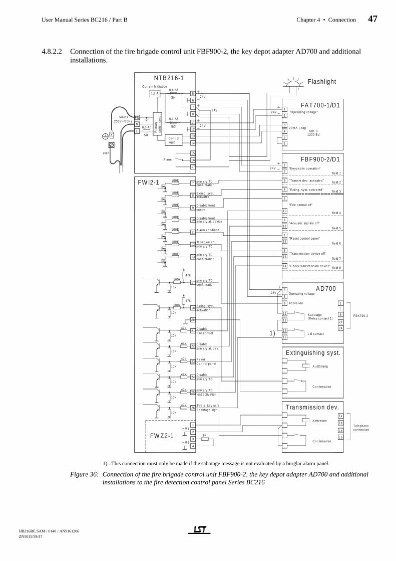
4.8.2.2 Connection of the fire brigade control unit FBF900-2, the key depot adapter AD700 and additionalinstallations.
1)...This connection must only be made if the sabotage message is not evaluated by a burglar alarm panel.
Figure 36: Connection of the fire brigade control unit FBF900-2, the key depot adapter AD700 and additionalinstallations to the fire detection control panel Series BC216
5
6
7
8
L
N
PE
0,5 At
0 ,8 A f
Prim
ary
switc
hco
ntr.
C u rren t lim ita tion
1 ,8 A
M ains230V ~/5 0H z
24V
N TB 216-1
S i1
S i4
12
11
13
14
0,1 Af
S i3
FW I2-1
FB F900-2/D 11
2
1 00E
1 00E8
7
C on tro llog ic
yegn
24V
FS K70 0-2
1
A D 700O perating vo lta ge
1 00E
1 00E
10 k
47 k100k
17
10 k
100k18
47 k
C on firm ation
A us lösung
E xtingu ish ing syst.
La
Lb
Ta
Tb
connectionTe leph one
24 V
A ctiva tion
C on firm ation
T ransm iss ion dev.
7
8
9
12
11
16
15
Activa tion
S ab otage(R e lay con tac t 1)
L id contac t
6
23
24
16
15
17
A larm
1
2
3
4
FW Z2-1H M 1
H M 2
47k
10 k
47k
10 k
47k
10 k
47k
10 k
47k
10 k
47k
10 k
26
25
24
23
22
21
1 00E
1 00E
11
12
13
14
11
12
8
7
10
6
5
3
4
FA T700-1/D 11
2"O pera ting vo ltage"
A dr. 0
5
4
3
6
1 200 B d
1 00E13
9
10
fie ld 1
fie ld 2
fie ld 3
fie ld 4
fie ld 5
fie ld 6
fie ld 7
fie ld 8
F lash light
24 V
24V
1K
2 4V
20m A-Loop
20
1)
p rim ary TDcon firm ation
E xting . syst.a ctiva ted
D isab le m entcontro l
D isab le m entp rim ary a l. dev ice
A larm cond ition
D isab le m entp rim ary TD
p rim ary TDcon firm ation
p rim ary TDcon firm ation
E xting . syst.a ctiva tion
D isab leF ire contro l
D isab lep rim ary a l. dev.
R esetC on tro l pa ne l
D isab lep rim ary TD
p rim ary TDtes t activa tion
F ire b . key sa feS abotage s ign .
"C heck transm iss ion de vice"
"Transm iss ion dev ice off"
"R eset contro l pan el"
"Acoustic s igna ls o ff"
"F ire contro l o ff"
"Ex ting . sys t. ac tiva ted"
"Transm .d ev. activated"
"Ke ypa d in opera tion"
HB216BE.SAM / 0140 / AN9161206 ZN5015/59/47
User Manual Series BC216 / Part B Chapter 4 • Connection 47
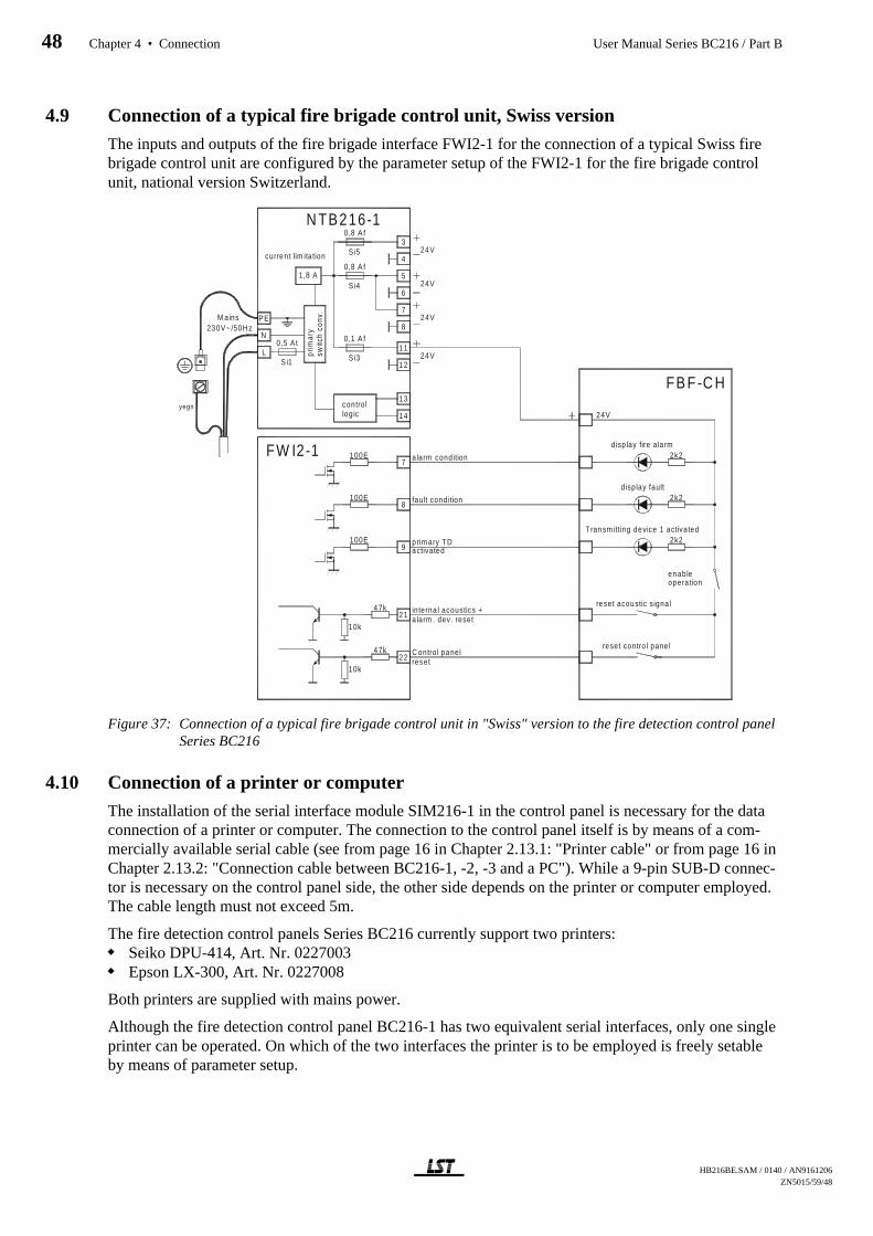
4.9 Connection of a typical fire brigade control unit, Swiss version
The inputs and outputs of the fire brigade interface FWI2-1 for the connection of a typical Swiss firebrigade control unit are configured by the parameter setup of the FWI2-1 for the fire brigade controlunit, national version Switzerland.
Figure 37: Connection of a typical fire brigade control unit in "Swiss" version to the fire detection control panelSeries BC216
4.10 Connection of a printer or computer
The installation of the serial interface module SIM216-1 in the control panel is necessary for the dataconnection of a printer or computer. The connection to the control panel itself is by means of a com-mercially available serial cable (see from page 16 in Chapter 2.13.1: "Printer cable" or from page 16 inChapter 2.13.2: "Connection cable between BC216-1, -2, -3 and a PC"). While a 9-pin SUB-D connec-tor is necessary on the control panel side, the other side depends on the printer or computer employed.The cable length must not exceed 5m.
The fire detection control panels Series BC216 currently support two printers:Seiko DPU-414, Art. Nr. 0227003Epson LX-300, Art. Nr. 0227008
Both printers are supplied with mains power.
Although the fire detection control panel BC216-1 has two equivalent serial interfaces, only one singleprinter can be operated. On which of the two interfaces the printer is to be employed is freely setableby means of parameter setup.
5
6
7
8
L
N
PE
0 ,5 At
0,8 A f
prim
ary
switc
hco
nv.
cu rrent lim ita tion
1,8 A
M ains230V~ /50H z
24V
24V
N TB216-1
Si1
S i4
12
11
13
14
0,1 A f
S i3
21
22
FW I2-1
FB F-C H
display fire a larm
2k2
2k2
disp lay fault
reset acoustic signal
reset contro l pane l
100E
100E8
7
47k
10k
47k
10k
contro llog ic
yegn
p rim ary TD100E9
24V
activated
a larm condition
fau lt cond ition
in terna l acoustics +a larm . dev. reset
4
324VSi5
0,8 A f
T ransm itting device 1 activated2k2
24V
resetC ontro l panel
enableopera tion
HB216BE.SAM / 0140 / AN9161206ZN5015/59/48
48 Chapter 4 • Connection User Manual Series BC216 / Part B
With the fire detection control panel BCnet216, only one interface is available at every BCnet sectionalcontrol panel. Practically you can connect one printer or one different serially activated device each toevery BCnet sectional control panel of a BCnet216.
The serial interface module SIM216-1 is designed with isolated potentials so that the printer or com-puter can be connected or disconnected during the operation of the fire detection control panel SeriesBC216 or a mains-operated printer can be switched on and off without impairing the function of thepanel.
Nevertheless, you may never connect or disconnect the serial interface module SIM216-1 from the cen-tral processing board prior to eliminating all voltage on the control panel!
Be careful not to touch a voltage carrying part of the control panel with the metallic case of the 9-pinSUB-D connector when connecting and disconnecting. Thereby you may cause a short circuit whichcan considerably damage the control panel. Appropriately proceed with caution when connecting anddisconnecting the printer cable (this is valid similarly for the connection cable to a PC).Always secure the printer cable inside the control panel case pull-relievedly by means of cable binders,so that the connector cannot be teared out inattentively.
Under no circumstances connect a cable to a serial interface module if it is not adequately secured tothe central processing board. By an inadvertent pull on the cable, a module which is fixed by insuffi-ciently tightened screws may be moved, which can lead to internal short circuits; this may cause con-siderable damage to the control panel.
HB216BE.SAM / 0140 / AN9161206 ZN5015/59/49
User Manual Series BC216 / Part B Chapter 4 • Connection 49

5 Commissioning
This chapter is devoted mainly to providing general information aimed at facilitating rapid and success-ful commissioning of the fire detection control panel BC216-1 or of the BCnet sectional control panelsBC216-2 and BC216-3 of the fire detection control panel BCnet216.
The major prerequisites for a successful commissioning are the expert installation and the correct con-nection of the external components of the fire detection system to the control panel.
5.1 Preparation
Prior to commissioning, follow the checklist below and check the following points on the basis of theexisting control panel structure:
Central processing board ZTB216-1 and ZTB216-2:Is the flat cable of the display and operating board ABB216-1 securely plugged into plug ST1?
Power unit NTB216-1:Are the protective conductor and the equipotential busbar connected to the rear of the control panelcase?Is the protective earth connection between mains terminal and rear of the control panel caseestablished?Is the protective cover of the parts carrying high voltage firmly screwed on?Are all mounting screws of the unit securely tightened (protection is fully effective only then!)?Is the supply for external devices connected correctly?Is the monitored siren output (usually parameterized as the primary alarming device) properly wiredor are the terminals equipped with an end of line resistor if no device is connected?Are the INFO bus and INFO supply lines connected properly?Is the current of the INFO bus set to 20mA (JP1 connected)?Are the alarm and fault relay contacts properly connected?Are the flat cables for the auxiliary outputs properly connected to the connectors ST1 and ST2?Are the stand-by batteries charged?
Network interface NIF5-1 (only with the fire detection control panel BCnet216):Are the incoming and the outgoing network cables connected correctly?Is the network cable as a whole laid as a circle without branch-offs?Are the shielding wires of the incoming and the outgoing network cable isolated from each otherand connected to the correct terminals?
Fire brigade interface FWI2-1:Are the transmitting devices properly connected?Are inputs and outputs properly allocated and connected?
Fire brigade interface additional board FWZ2-1:Is the board properly connected and secured?Are the monitored transmitting devices properly connected?Is every unused monitored output for a transmitting device either equipped with an end of line resis-tor or parameterised as "Not defined"?
Conventional detector interface GIF8-1:Are the detector lines properly connected?Is the end of line resistor installed with the last detector of each detector line?Are all detectors in normal condition?Is every unused detector line of a conventional detector interface closed with an end of line resistoror set as "Not defined"?
Loop interface LIF64-1:Is the loop properly connected?
HB216BE.SAM / 0140 / AN9161206ZN5015/59/50
50 Chapter 5 • Commissioning User Manual Series BC216 / Part B
Are all addresses on the devices connected to the loop correctly set?Are all detectors in normal condition?
LED-display field LAB48-1:Is the flat cable securely connected to the connector ST2 of the display and operating boardABB216-1?
Other additional modules:Is the module correctly plugged in and connected?
Recheck once again the earth-connection of the control panel case: Cover and bottom part must beelectrically interconnected during operation.
Check if all mounting screws of the modules employed are securely tightened. This is particularly de-cisive for the effectiveness of the EMC measures taken for all modules!
If you have a PC keyboard at your disposal, connect this to the connector ST8 ("connector for PC key-board") of the central processing board ZTB216-1 or ZTB216-2. As part of the commissioning, you canoperate and set the parameters of the control panel with the PC keyboard.
If you wish to set the parameters by means of a PC (Notebook) using the parameter setup softwarePARSOFT, you must have a serial interface module SIM216-1 plugged onto the central processingboard ZTB216-1 (on ST6 or ST7) and configure the interface with the control panel keypad to "PAR-SOFT". The PC must be connected with the SUB-D connector of the SIM216-1 (see from page 16 inChapter 2.13.2: "Connection cable between BC216-1, -2, -3 and a PC").
In order to exclude undesired alarms and activation of actuations during commissioning, the alarmingdevices, the transmitting devices and the actuations must be disabled (e.g., by disconnecting the ca-bles). In cases involving a greater safety risk (e.g., activation of extinguishing systems, disabling pro-duction lines, etc.) you should have additional mechanical and/or electrical safeguards installed by thepersons responsible for these systems in order to prevent undesired activation or shut downs of thesefacilities.
Monitored outputs, which you disconnect for safety reasons, must be equipped with adequate replace-ment resistors during commissioning.
After completed commissioning, all previously disabled installations must be enabled again!
5.2 Power supply connection
Plug the mains power connector in the NTB216-1 and switch on the mains power. A short signal fromthe installed buzzer becomes audible and the control panel or BCnet sectional control panel starts tooperate. The initialisation phase takes a few seconds, after which the light-emitting diode "OPERA-TION" is illuminated and a standard date (e.g., 01.01.2001 00:00) appears on the LC-display. Approxi-mately 10 seconds later, the fault signal [ENERGY FAULT stand-by battery] is indicated since nostand-by batteries are connected at that stage.
Connect the stand-by batteries while ensuring correct polarity (positive = red, negative = black cable).No power supply faults must be active on the control panel after 10 seconds.
It is imperative to adhere to the sequence: First switch on the mains power, then connect the stand-bybattery. The power unit of the fire detection control panel is current-limited and short-circuit proof. Inthe event of fault in the cabling of the fire detection system, the current limitation will limit the effectseven in the event of a short-circuit. However, the stand-by battery is able to supply a very high currentin the event of a short-circuit. This current will rapidly blow the fuses but considerable damage can bethe result by that time.
Connecting the power supply does not influence the configuration parameters entered at an earlierstage.
HB216BE.SAM / 0140 / AN9161206 ZN5015/59/51
User Manual Series BC216 / Part B Chapter 5 • Commissioning 51

5.3 Setting parameters and function tests
The fire detection control panel BC216-1 or the BCnet sectional control panels BC216-2 and BC216-3of the fire detection control panel BCnet216 are supplied without module parameter setup from the fac-tory. It is therefore indispensable as part of commissioning that you establish the necessary configura-tion by means of individual parameter setup (probably by means of a priorly executed AUTO-setup).Notice the hints given in User Manual / Part C.
Set the site-specific parameters of the control panel in accordance with the individual requirements ofthe fire detection system. The following basic options, which can also be combined, are available:
AUTO-setup: By automatic setup you set the control panel parameters in accordance with the hard-ware configuration of the control panel to default values or adjust the existing control panel parame-ters merely to newly added hardware components automatically. Based on this standardconfiguration, you subsequently set the parameters to the individual values using one of the two fol-lowing options.With BCnet sectional control panels you have to execute the AUTO-setup individually on everysectional control panel via keypad or via connected PC keyboard. You can change the standardsetup thereby established on the main operating unit by using PARSOFT-2.You set the parameters of the control panel via control panel keypad or via a connected PC key-board.Individual setting of parameters on every sectional control panel is possible only partially withBCnet sectional control panels and therefore is not recommended. For example, when setting theparameters on every BCnet sectional control panel, no compatibility test of the parameters of thesingle sectional control panels in accordance to the overall control panel is made. Nevertheless, thecharacteristics of the GSSnet members must be determined on the main operating unit by using a PCand software PARSOFT-2.You set the parameters of the control panel BC216-1 by means of PC and software PARSOFT-1.You set the parameters of the BCnet sectional control panels via PC and software PARSOFT-2 fromthe sectional control panel defined as main operating unit.
You can overwrite these parameters as often as you wish.
When setting the parameters on the control panel itself, all parameters entered by you will be saved in atemporary memory for the time being. The content of this memory will be transferred to the permanentmemory of the control panel only on completion of the parameter setup. Should you press the reset-button or de-energise the control panel before completion of the parameter setup, the set parameter datawill be lost!
You can also set the control panel parameters prior to the installation of the control panel. The set pa-rameters are filed in a permanent semi-conductor memory and will be kept practically for an unlimitedperiod of time even without power supply. Only the indication of date and time is dependent on thepower supply and must therefore be reset after the power supply has been connected.
Before leaving the parameter setup mode, you have to change the initial value of the installer code (seeUser Manual Series BC216 / Part A) to your own personal value. This serves to prevent unauthorisedand abusive manipulation of the fire detection control panel. Exiting the parameter setup mode withoutpriorly changing the delivery value is not possible.
In the event of unauthorized or improper operation or parameter setup the entire fire detection systemmay malfunction or become entirely ineffective in extreme cases! It is also possible that automatic firecontrols (even extinguishing systems - danger to life!) and alarming devices may be inadvertently acti-vated and help personnel (fire brigade) may be called.
After the parameter setup, check all system functions carefully. Ensure that all system parts operate asyou as specialist installer of fire detection systems determined during the project phase of the entiresystem.
If you have performed the parameter setup of a fire detection control panel BC216-1 without PC andparameter setup software PARSOFT-1 directly on the control panel, it is indispensable to print out the
HB216BE.SAM / 0140 / AN9161206ZN5015/59/52
52 Chapter 5 • Commissioning User Manual Series BC216 / Part B
entered data for documentation (see User Manual / Part C). Keep the print-out in a safe place - theseconfiguration data are very important, e.g., in the event of a repair exchange.
5.4 Recalculation of the bridging time
Once you have ensured that all system parts are connected and are operating correctly, you must recal-culate the mains failure bridging time of the system or of the system section surveilled by the BCnetsectional control panel. For this purpose the stand-by battery must be charged so that its voltage doesnot drop below 24V during the measuring process described in the following.
Connect a suitable ampere-meter into the positive connection line (red cable) of the stand-bybattery.Put the system in normal condition.Switch off the control panel power supply, wait until "Mains fault" is indicated (this can take up to5 minutes!) and reset the built-in buzzer by pressing the button 'Silence buzzer'.Measure the current supplied by the stand-by battery for the entire system in the state of fault.Activate an alarm and measure the current in the case of alarm (with activated optical and acousticsignalling devices, activated key safe, etc.!) For system parts which you may not activate for testing(e.g., the activation of an extinguishing system), you will have to add the calculated current value ofthat system part to the measured power consumption.
You have to ensure priorly that the alarm activation is recepted as "test alarm" from all persons con-cerned. Coordinate your work with the user of the fire detection system (e.g., with the fire preventionofficer) and the fire brigade.
With the measured current values, recalculate the required capacity of the stand-by battery (see frompage 14 in Chapter 2.8.1: "Determining the required capacity of the stand-by battery"). If the measuredcurrent essentially differs from the planned value calculated earlier, determine the reason for this. Youmust be able to safely exclude that the cause are faults in the cabling or faulty equipment.
With the fire detection control panel BCnet216 you have to carry out the proceedings written before forevery BCnet sectional control panel separately. In this case, "system" refers to the system sectionwhich is surveilled by the corresponding BCnet sectional control panel.
5.5 Concluding activities
Clearly mark the stand-by batteries with the planned expiry date (defined by the battery manufacturer).
Instruct the user demonstrably on all functions of the control panel (and of course of the entire fire de-tection system) relevant to the user and enter all data in the system book.
Change the initial value of the user code (see User Manual Series BC216 / Part A) to the value re-quested by the user. This serves to prevent unauthorised and improper operation of the fire detectioncontrol panel.
Keep the user code in a place agreed with the help personnel (fire brigade) which is only accessible bythat personnel (e.g., in the fire brigade control panel, in the fire brigade key safe, etc.).
5.6 Reconditioning
The control panel indicates all faults recognised by the control panel in text on the LC-display. De-tailed additional information on any fault occurred can be called up for each fault by means of the'INFO'-button. This information is generally sufficient for a trained specialist installer to rapidly correctthe fault.
"Fault" means a fault in the installed fire detection system, but not the activation of a fault detector.
HB216BE.SAM / 0140 / AN9161206 ZN5015/59/53
User Manual Series BC216 / Part B Chapter 5 • Commissioning 53
5.6.1 Lost installer code
It is not possible to read out an installer code from the control panel. Once the installer code saved inthe control panel has been lost, access to authorisation level 3 can only be gained with the help of themanufacturer of the control panel or his national representative.
For this you have to press the '↑ '-button in the menu point [Authorization code:] (i.e., in authorisationlevel 1). The following appears on the LC-display for 5 seconds:
the date and time anda 5-digit key number.
The indicated date and key number must be given to the manufacturer or his representative who willdetermine a code number of the day from these two pieces of information. You then enter this codenumber of the day as installer code, by this automatically delete the forgotten installer code and, as firstadditional step, you have to establish a new installer code (see User Manual Series BC216 / Part A).
The code number of the day is only valid as entry code of this control panel on the day displayed asdate on the control panel LC-display when reading out the key number.
HB216BE.SAM / 0140 / AN9161206ZN5015/59/54
54 Chapter 5 • Commissioning User Manual Series BC216 / Part B

6 Specifications
Please adhere to the absolute limit values for the load current of the control panel BC216-1 and theBCnet sectional control panels BC216-2 and BC216-3: The total current of all devices (detectors, sig-nalling devices, actuations, etc.) supplied by the power unit of the corresponding (sectional) controlpanel including the (sectional) control panel itself
must not exceed the value of 1.8A at any time.
The automatic current limitation of the power supply unit is set to this value. This value must neitherbe exceeded in case of an alarm. Please take into account that the fire detection system must also workwithout restrictions in the event of a stand-by battery failure, even peak output currents (e.g., for alarm-ing devices) must be covered by the power unit on its own without the help of the energy stored in thestand-by battery.
6.1 Fire detection control panel BC216-1/xx, BC216-2/xx, BC216-3/xxCase
Installation Wall installation, surface typeMaterial Steel sheet, 1mm, powder coatedColour Grey-white, RAL 9002Protection class IP30Dimensions w × h × d 420 × 520 × 120 (mm)
Panel power consumption from the 24V stand-bybattery upon mains failure,without function modules, fault relay released,without FWI, without SIM216
BC216-1: 90mABC216-2 (including NIF5-1): 125mA (active network)BC216-3 (including NIF5-1): 90mA (active network)
Number of function modules 2Number of detector zones, total Max. 144, depending on the function modules usedWeight without battery Approx. 6kgAmbient temperature -5°C to +50°CRelative humidity of air 95% (not condensing)Approvals
Austria BC216-1/A1 FT 14/147/1/99Germany BC216-1/Dx VdS G 201017Hungary BC216-1/H1 EMILABS 85/2000
6.2 Power unit NTB216-1Mains
Mains voltage 230VAC +10/-15 %, 50HzConnected load 60VAPower consumption Max. 0.26ARated output voltage Typically 28VDCPeak output current total Max. 1.8A
Stand-by batteryRated voltage 24VFinal charge voltage at 25°C 27.3VCharge current Max. 1.7A, current limitedCapacity Max. 34AhConnection 2.5A slow-blow fuse protected
Connection internal/external devices 2 × 0.8A fast blow fuse, separately protected0.1A fast blow fuse protected for INFO bus devices etc.
Connection type Screw terminalsWire cross section Max. 1.5mm²
Dimensions w × h × d 120 × 230 × 50 (mm)Weight 500g
HB216BE.SAM / 0140 / AN9161206 ZN5015/59/55
User Manual Series BC216 / Part B Chapter 6 • Specifications 55

6.2.1 Primary alarming deviceLine monitoring By negative voltage in the normal condition, ca. -1.2VMaximum continuous load 150mA, short-circuit proofMaximum peak current 0.4A
6.2.2 INFO busNumber of connected devices 8Interface 20mA-current loopBaud rate 600, 1200 (standard), 2400 baud, parameterizableLine resistance (total) Number of devices Maximum value
1 1000Ω2 860Ω4 620Ω6 400Ω8 160Ω
6.2.3 Contact outputs for alarm relay and fault relayContact type 1 dry change-over contact eachContact load 60V/1A/30W
6.2.4 NTB auxiliary outputsNumber 2 × 8Contact type Open collector outputsSwitching current Max. 35mAConnection type Flat cable connector, corresponding to the relay module
RL58-1 and RL58-2. Note: These outputs are not permittedfor controlling external devices!
6.3 Conventional detector interface GIF8-1Power consumption at 24V Typically 50mALine voltage Typically 20VNumber of detector lines and detector zones 8Detector addressing 0, ..., 63Line current Typically 3.7mAEnd of line resistor 5.6kΩLine resistance Max. 50Ω per coreConnection type Screw terminals
Wire cross section Max. 1.5mm² (single wire)Ambient temperature -5°C to +50°CDimensions l × w × h 132 × 74 × 10 (mm)Weight 80g
6.4 Loop interface LIF64-1Power consumption at 24V (w/o detectors, modules) Typically 25mANumber of detector zones Max. 128Number of detectors, modules
ADM technology Max. 198 elements (99 detectors + 99 modules)ADMPRO technology Max. 126 elements
Loop quiescent current Typically 300µA (per connected detector or module)Loop total current (detectors, modules, sirens, etc.) Max. 130mA (at reduced line resistance)Loop quiescent voltage Typically 26V (ADMPRO) or 29V (ADM)Loop line 2-core twisted, shielded or not shielded
Line resistance Max. 50Ω per coreLine capacity Max. 400nF
Connection type Screw terminalsWire cross section Max. 2.5mm² (single wire)
Ambient temperature -5°C to +50°C
HB216BE.SAM / 0140 / AN9161206ZN5015/59/56
56 Chapter 6 • Specifications User Manual Series BC216 / Part B
Dimensions l × w × h 132 × 74 × 10 (mm)Weight 80g
6.5 Fire brigade interface FWI2-1Power consumption at 24V Typically 4mA (both relays released)
+20mA per activated relayRelay outputs 2
Switching capacity per contact 60V/1A/30WContact service life 3 × 10⁵
Open collector outputs 9Switching current Max. 35mASwitching voltage Max. voltage for external devices
Inputs, activated with earth 3Input voltage Activated (NO): Max. 3V
Not activated (NO): At least 12VInputs, activated with +24V 6
Input voltage Activated (NO): At least 12VNot activated (NO): Max. 3V
Inputs with impulse triggering Impulse duration min. 1 secondConnection type Screw terminals
Wire cross section Max. 1.5mm² (single wire)Ambient temperature -5°C to +50°CDimensions l × w × h 132 × 74 × 10 (mm)Weight 70g
6.6 Fire brigade interface additional board FWZ2-1Power consumption at 24V Typically 4mA (both monitored outputs not connected)
Max. 28mA (both monitored outputs connected)Monitored outputs 2Maximum continuous load per output 150mA, short-circuit proofMaximum peak current per output 0.4AMonitoring current at 24V 4 / 8 / 12mA (approximate values),
jointly parameterizable for both outputsConnection type Screw terminals
Wire cross section Max. 1.5mm² (single wire)Ambient temperature -5°C to +50°CDimensions l × w × h 117 × 74 × 10 (mm)Weight 70g
6.7 LED-display field LAB48-1Power consumption at 24V Typically 2mA, without active light-emitting diode
0.25mA per active light-emitting diodeAmbient temperature -5°C to +50°CDimensions l × w × h 176 × 120 × 15 (mm)Weight 60g
6.8 Serial interface module SIM216-1Power consumption at 24V Typically 10mAInterface RS232-C, galvanically isolated
Lines RxD, TxD, CTS/DTRBaud rate 1200, 2400, 4800, 9600, 38400, 57600 baud
Connection type D-SUB connector, 9-pinAmbient temperature -5°C to +50°CDimensions l × w × h 70 × 45 × 20 (mm)Weight 50g
HB216BE.SAM / 0140 / AN9161206 ZN5015/59/57
User Manual Series BC216 / Part B Chapter 6 • Specifications 57

6.9 Network interface NIF5-1Power consumption at 24V Typically 25mAInterface RS485, galvanically separated
Cable length between two NIF5-1 Max. 1200mConnection type Screw terminals
Wire cross section Max. 2.5mm² (single wire)Ambient temperature -5°C to +50°CDimensions l × w × h 95 × 70 × 25 (mm)Weight 50g
6.10 Network cableComputer network cable, core number 4×2×AWG24/1 S/FTP, category 5, twisted in pairs, polyolefine isolated, with following technicalspecifications:Loop resistance Max. 16.8Ω/100m at 20°CMutual capacitance 4.9nF/100m at 1kHzImpedance 100 ± 15Ω at 1kHzAttenuation (50MHz) Max. 14dB/100mJacket FR-PVC/FR-I,S∅ HOuter diameter 6.50 mmMinimum bending radius 52 mmMaximum tensile strength 25 kgWire cross section 0.51mmShield Alu-polyester foil + Cu interlacingAmbient temperature -20°C to +75°CWeight 51kg/km
6.11 Auxiliary case GEH216-4Installation Wall installation, surface typeMaterial Steel sheet, 1mm, powder coatedColour Grey-white, RAL 9002Protection class IP30Dimensions w × h × d 420 × 520 × 120 (mm)Weight without installations Approx. 2kg
6.12 Battery bracket BK216-1Material Steel sheet, 1mm, powder coatedColour Grey-white, RAL 9002Dimensions l × w ×h 380 × 175 × 90 (mm)Weight Approx. 90g
6.13 Mounting bracket BW216-1Material Steel sheet, 1mm, galvanizedDimensions l × w × h 380 × 100 × 20 (mm)Weight Approx. 30g
HB216BE.SAM / 0140 / AN9161206ZN5015/59/58
58 Chapter 6 • Specifications User Manual Series BC216 / Part B

7 Index
Alarm resistor, 36Alarming device
- primary, 30Approvals, 55Auto-setup, 52
- FWI, 38- GIF8-1, 35- LIF64-1, 36- supervising current, 41
Auxiliary case GEH216-4, 15- installation, 26
Auxiliary outputs- connection, 33
Basic version, 9Battery bracket BK216-1, 15,
26Case, 9Central processing board
ZTB216-1, ZTB216-2, 10Commissioning, 50Componentries
- installation, 19Connection, 28
- conductor cross section, 28- conventional detector interface,
35- external devices, 29- fire brigade interface additional
board FWZ2-1, 41- fire brigade interface FWI2-1,
37- INFO bus, 31- loop interface, 36- mains power, 29- relay modules, 33- shielded cables, 28- signalling devices, 30- stand-by battery, 29- summary alarm, 32- summary fault, 32
Conventional detector interfaceGIF8-1, 11
- connection, 35- installation, 20
Display and operating boardABB216-1, 11
Earth leakage- monitoring, 11
External devices- connection, 29
Fire brigade control unit, 12Fire brigade interface additional
board FWZ2-1, 12- connection, 41- current limitation, 41- installation, 20- line monitoring, 41
Fire brigade interface FWI2-1,12
- connection, 37- installation, 20
Fire brigade key depot, 12Fire brigade key safe, 12Function module, 11Function tests, 52GSSnet wiring, 34INFO bus, 10
- connection, 31Installation, 17
- auxiliary case, 26- important hints, 7- panel case, 18- place of assembly, 17
Installer code- code number of the day, 54- lost, 54
Interface- RS232-C, 13
Key depot, 12Key safe, 12LED-display field LAB48-1, 13
- designation, 22- installation, 21
Loop, 12Loop interface LIF64-1, 12
- connection, 36- installation, 20
Mains power- connection, 29
Mains shut-down- bridging time, 14, 53
Measured value- print-out, 16
Mounting bracket BW216-1,11, 15, 26
- installation, 26Network interface NIF5-1
- installation, 24Network redundant alarm con-
verter NNU5-1, 45PC connection cable, 16PC keyboard, 51Power supply, 51Power unit NTB216-1, 10Printer, 15
- connection, 48- Epson LX300, 15- event printer, 15- printer cable, 16- Seiko DPU-414, 15- service printer, 16
Reconditioning, 53Redundant alarm line, 45Relay module
- connection, 33- installation, 24
Scope of delivery, 8Serial interface module
SIM216-1, 13- installation, 23
Serial interface moduleSIM216-2, 13
- installation, 23Service print-out, 16Setting parameters, 52Settings print-out, 16Shielded cables, 18, 28Signalling devices
- connection, 30Siren output, 30
- current limitation, 31- line monitoring, 31
Software
- version number, 7Specifications, 55Stand-by battery
- capacity, 14, 53- connection, 29- connection cable, 30- expiry date, 53- installation, 25, 26- installation position, 13- installation space, 13- parallel-connecting, 13, 30- total discharge, 11
Summary alarm- connection, 32
Summary fault- connection, 32
Transmitting device- connection, 12- primary, 38
User code, 53Version number, 7
User Manual Series BC216 / Part B Chapter 7 • Index 59


