6
AMERICAN FLOW CONTROL 4 3/4” WATEROUS TREND FIRE HYDRANT
| Date post: | 06-Mar-2018 |
| Category: |
Documents |
| Upload: | nguyenthuan |
| View: | 214 times |
| Download: | 1 times |

AMERICAN FLOW CONTROL 4 3/4” WATEROUS TRENDFIRE HYDRANT

BRONZE-TO-BRONZE SEATINGO-ring protected bronze valve seat threads into a bronze insert in the hydrant bottom.
STAINLESS STEEL BOLTINGBELOW GRADELong-term corrosion resistance.
EPOXY-COATEDLOWER COMPONENTSDuctile iron base and lower and upper valve washers are fusion bond epoxy coated for corrosion resistance.
FLAT BOTTOM ANDSTRAPPING LUGSAll standard to make solid, straight installation faster and easier.
ALL-BRONZE DRAINNo composition rubber, plastic or leather face to wear, peel or crack.
TRAFFIC SECTIONParts are designed to break at the ground line. Simple low-cost repair kit available.
INTEGRAL CAP NUT AND LOWER WASHERProtects rod threads from corrosion and makes servicing easy. Valve assembly is locked in place.
TWO-PIECE OPERATING NUTDuctile iron upper section provides strength for wrenching. Lower portion is bronze for smooth operation and corrosion resistance.
MECHANICALLY ATTACHED NOZZLESPatented design allows field replacement of damaged nozzles in minutes by one person. Uses no pins or set screws that can become dislodged or lost.
CENTRIFUGALLY CASTDUCTILE IRON BARRELSStronger, smoother and more uniform than static cast barrels.
360° NOZZLE SECTION ROTATIONThe Waterous stainless steel retaining ring system allows 360° rotation by loosening only four flange bolts and turning the nozzle section to the exact position desired.
TRAVEL STOP NUTProvides a positive limit to main rod travel.
DUCTILE IRON NOZZLESECTION AND STAND PIPEIs provided with an epoxy primer and polyurethane top coat for improved durability, color and gloss retention.
CONSTRUCTIONFully complies with ANSI/AWWA C502 and is available UL Listed and Approved by FM Approvals in applicable configurations.

SECTIONAL DRAWINGS/DIMENSIONS
TYTON is a registered trademark of United States Pipe and Foundry Co., LLC.®
4 3/4” TREND FIRE HYDRANT
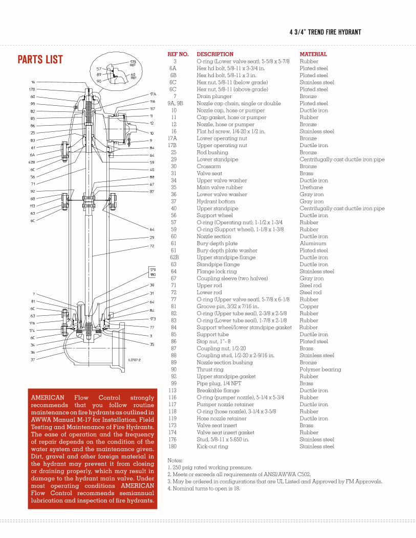
REF NO. DESCRIPTION MATERIAL 3 O-ring (Lower valve seat), 5-5/8 x 5-7/8 Rubber 6A Hex hd bolt, 5/8-11 x 3-3/4 in. Plated steel 6B Hex hd bolt, 5/8-11 x 3 in. Plated steel 6C Hex nut, 5/8-11 (below grade) Stainless steel 6C Hex nut, 5/8-11 (above grade) Plated steel 7 Drain plunger Bronze 9A, 9B Nozzle cap chain, single or double Plated steel 10 Nozzle cap, hose or pumper Ductile iron 11 Cap gasket, hose or pumper Rubber 12 Nozzle, hose or pumper Bronze 16 Flat hd screw, 1/4-20 x 1/2 in. Stainless steel 17A Lower operating nut Bronze 17B Upper operating nut Ductile iron 25 Rod bushing Bronze 29 Lower standpipe Centrifugally cast ductile iron pipe 30 Crossarm Bronze 31 Valve seat Brass 34 Upper valve washer Ductile iron 35 Main valve rubber Urethane 36 Lower valve washer Gray iron 37 Hydrant bottom Gray iron 40 Upper standpipe Centrifugally cast ductile iron pipe 56 Support wheel Ductile iron 57 O-ring (Operating nut), 1-1/2 x 1-3/4 Rubber 59 O-ring (Support wheel), 1-1/8 x 1-3/8 Rubber 60 Nozzle section Ductile iron 61 Bury depth plate Aluminum 61 Bury depth plate washer Plated steel 62B Upper standpipe flange Ductile iron 63 Standpipe flange Ductile iron 64 Flange lock ring Stainless steel 67 Coupling sleeve (two halves) Gray iron 71 Upper rod Steel rod 72 Lower rod Steel rod 77 O-ring (Upper valve seat), 5-7/8 x 6-1/8 Rubber 81 Groove pin, 3/32 x 7/16 in. Copper 82 O-ring (Upper tube seal), 2-3/8 x 2-5/8 Rubber 83 O-ring (Lower tube seal), 1-7/8 x 2-1/8 Rubber 84 Support wheel/lower standpipe gasket Rubber 85 Support tube Ductile iron 86 Stop nut, 1”- 8 Plated steel 87 Coupling nut, 1/2-20 Brass 88 Coupling stud, 1/2-20 x 2-9/16 in. Stainless steel 89 Nozzle section bushing Bronze 90 Thrust ring Polymer bearing 92 Upper standpipe gasket Rubber 99 Pipe plug, 1/4 NPT Brass 113 Breakable flange Ductile iron 116 O-ring (pumper nozzle), 5-1/4 x 5-3/4 Rubber 117 Pumper nozzle retainer Ductile iron 118 O-ring (hose nozzle), 3-1/4 x 3-5/8 Rubber 119 Hose nozzle retainer Ductile iron 173 Valve seat insert Brass 174 Valve seat insert gasket Rubber 176 Stud, 5/8-11 x 5.650 in. Stainless steel 180 Kick-out ring Stainless steel
Notes:1. 250 psig rated working pressure.2. Meets or exceeds all requirements of ANSI/AWWA C502.3. May be ordered in configurations that are UL Listed and Approved by FM Approvals.4. Nominal turns to open is 18.
PARTS LIST
AMERICAN Flow Control strongly recommends that you follow routine maintenance on fire hydrants as outlined in AWWA Manual M-17 for Installation, Field Testing and Maintenance of Fire Hydrants. The ease of operation and the frequency of repair depends on the condition of the water system and the maintenance given. Dirt, gravel and other foreign material in the hydrant may prevent it from closing or draining properly, which may result in damage to the hydrant main valve. Under most operating conditions AMERICAN Flow Control recommends semiannual lubrication and inspection of fire hydrants.
AMERICAN Flow Control’s Waterous Trend hydrant exhibits a sleek and stylish design that blends perfectly with today’s modern architecture. The Trend is rated for 250 psig and meets or exceeds all of the requirements of ANSI/AWWA C502. Ductile iron construction assures strength and durability.
Introduced in 1967, the Trend fire hydrant provides real solutions to today’s system demands. With many cities experiencing increased pressure to stretch their dollars, it is important to note that the Trend hydrant can be maintained by just one person. The removal of four nuts and bolts allows access to all working parts.
The Trend hydrant has all the features you expect from a high-quality fire hydrant. The epoxy primer and polyurethane top coating system on external surfaces above grade provide a durable, high-gloss finish that will continue to look good for years without repainting. The all-bronze valve seat and bronze seat insert ensure that the Trend hydrant remains easy to repair. The Trend has been manufactured for many years while still maintaining parts interchangeability.
FEATURES
BENEFITS
SPECIFICATIONS
Trend standard features:• All-bronze drain• Travel stop nut located in top of hydrant • Easy 360° rotation of nozzle section• 250 psig working pressure rating• Shell tested at 500 psig• Two-part catalyzed epoxy primer and polyurethane coating system above grade
• Ductile iron nozzle section, upper and lower stand pipes and hydrant base• Lubrication chamber• Stainless steel bolting below grade• Bronze-to-bronze seating• Bronze cross arm• Design employs long-term part interchangeability
Easy Nozzle Section RotationThe Waterous Trend’s stainless steel flange lock ring allows 360° rotation of nozzle section by merely loosening four bolts and turning nozzle section to the exact position required. This is done without damage to barrel gaskets.
Lubrication ChamberO-rings help seal operating threads from water and debris.
All-Bronze DrainNo composition rubber, plastic or leather to wear, peel or crack.
Top Travel Stop NutHelps prevent stem buckling and damage to other components.
Fire hydrants shall meet or exceed ANSI/AWWA C502, latest revision. Rated working pressure shall be 250 psig, test pressure shall be 500 psig and hydrants shall include the following specific design criteria:
The nozzle section, upper and lower stand pipes and hydrant base shall be ductile iron.
External surfaces above grade shall be factory coated with an epoxy primer and a two-part polyurethane top coating.
The main valve closure shall be of the compression type, opening against the pressure and closing with the pressure. Nozzle section to be designed for easy 360° rotation by the loosening of no more than four bolts.
The valve opening diameter shall be 4-3/4 in. Hydrant must be designed so that removal of all working parts can be accomplished without excavating. The bronze seat shall be threaded into mating threads of bronze for easy field repair.
Bolting below grade shall be stainless steel.
The draining system of the hydrant shall be bronze and be positively activated by the main operating rod. Hydrant to be furnished with a sliding bronze drain valve. Sliding drain valves made of rubber, plastic or leather will not be allowed.
Hydrant must have an internal travel stop nut located in the top housing of the hydrant.
Hydrant operating threads to be factory lubricated. O-rings shall be furnished to help keep operating threads lubricated and protected from line fluid and from the weather.
Hydrant must have a traffic flange design allowing for quick and economical repair of damage resulting from a vehicle’s impact. Hydrants shall be AMERICAN Flow Control’s Waterous Trend (Model WB77-1).
4 3/4” TREND FIRE HYDRANT

AFC-3/11 - PDF
AMERICAN Flow Control
P.O. Box 2727Birmingham, AL 35202-2727Phone: 800-326-8051Fax: 800-610-3569Email: [email protected]
Waterous Company
125 Hardman Avenue SouthSouth St. Paul, MN 55075-2421Phone: 888-266-3686Fax: 800-601-2809Email: [email protected]
WWW.AMERICAN-USA.COM
Distributed By:
Product literature may become outdated. AMERICAN is not responsible for out-of-date information, errors or omissions.Please contact AMERICAN for the most current product information.
Trend Product Videos
EOE/Minority/Female/Veteran/Disability Rev 16.1


