FIRE Physics Basis (detailed version) C. Kessel for the FIRE Team Princeton Plasma Physics Laboratory FIRE Physics Validation Review March 30-31, 2004 Germantown, MD AES, ANL, Boeing, Columbia U., CTD, GA, GIT, LLNL, INEEL, MIT, ORNL, PPPL, SNL, SRS, UCLA, UCSD, UIIC, UWisc FIRE Collaboration http://fire.pppl.gov
Full operating space available within stress (1.3 margin) and heating allowables, except at EOB, li=0.85 where ≤ ref-2
Rampup consumes ≈ 40 V-sFlattop consumes ≈ 3 V-s
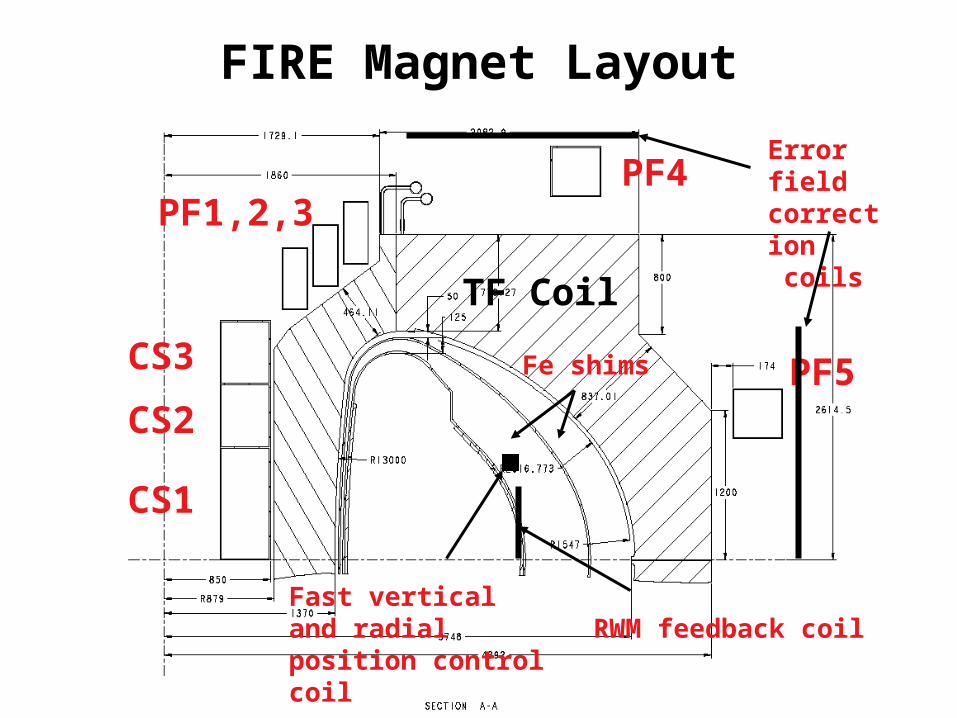
CS1
CS2CS3
PF1,2,3 PF4
PF5
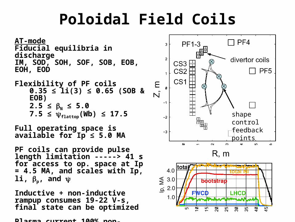
Poloidal Field CoilsAT-modeFiducial equilibria in dischargeIM, SOD, SOH, SOF, SOB, EOB, EOH, EOD
Flexibility of PF coils0.35 ≤ li(3) ≤ 0.65 (SOB & EOB)2.5 ≤ N ≤ 5.07.5 ≤ flattop(Wb) ≤ 17.5
Full operating space is available for Ip ≤ 5.0 MA
PF coils can provide pulse length limitation -----> 41 s for access to op. space at Ip = 4.5 MA, and scales with Ip, li, p, and
Inductive + non-inductive rampup consumes 19-22 V-s, final state can be optimized
Plasma current 100% non-inductive in flattop
shape control feedback points
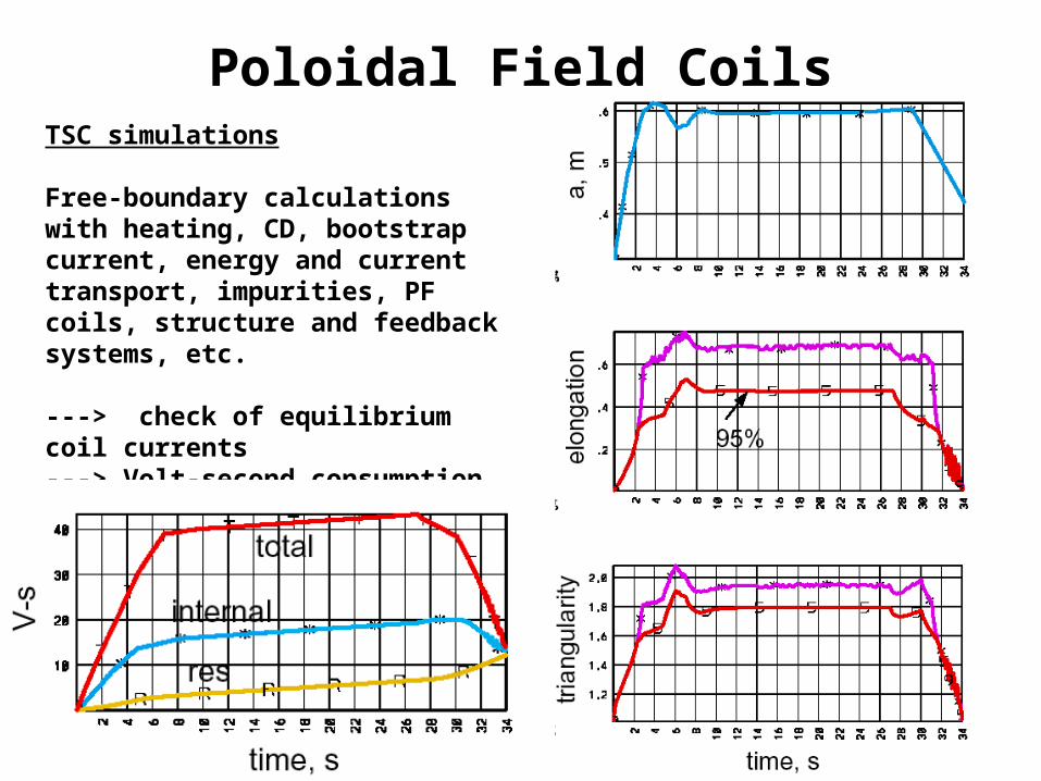
Poloidal Field CoilsTSC simulations
Free-boundary calculations with heating, CD, bootstrap current, energy and current transport, impurities, PF coils, structure and feedback systems, etc.
---> check of equilibrium coil currents---> Volt-second consumption---> Feedback control of vertical position, radial position, plasma current and shape
Vertical StabilityDesign passive structures to slow vertical instability for feedback control and provide a stability factor fs > 1.2
Passive stabilizers are 2.5 cm thick Cu, toroidally continuous on upper outboard and inboard sides
For most unstable plasmas (full elongation and low pressure), over the range 0.7 < li(3) < 1.1, the stability factor is 1.3 < fs < 1.13 and growth time is 43 < g(ms) < 19
Passive stabilizers Cladding
(ports provide poloidal cuts)
Cladding(large number of poloidal cuts)
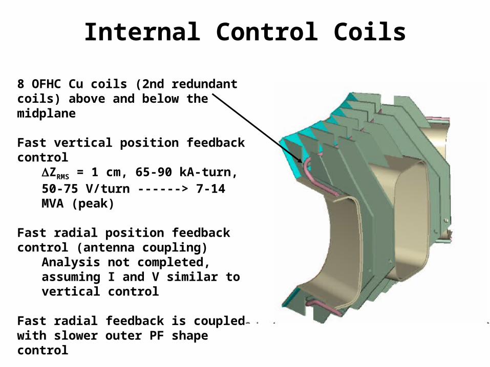
Internal Control Coils
8 OFHC Cu coils (2nd redundant coils) above and below the midplane
Fast vertical position feedback controlZRMS = 1 cm, 65-90 kA-turn, 50-75 V/turn ------> 7-14 MVA (peak)
Fast radial position feedback control (antenna coupling)
Analysis not completed, assuming I and V similar to vertical control
Fast radial feedback is coupled with slower outer PF shape control
These coils also used in startup to tailor field null
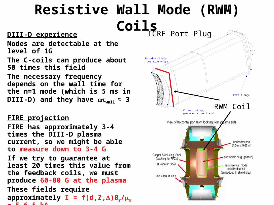
Resistive Wall Mode (RWM) Coils
Current strap, grounded at each end
Faraday shield(one side only)
Port flange
ICRF Port Plug
RWM Coil
DIII-D experienceModes are detectable at the level of 1GThe C-coils can produce about 50 times this fieldThe necessary frequency depends on the wall time for the n=1 mode (which is 5 ms in DIII-D) and they have wall ≈ 3
FIRE projectionFIRE has approximately 3-4 times the DIII-D plasma current, so we might be able to measure down to 3-4 GIf we try to guarantee at least 20 times this value from the feedback coils, we must produce 60-80 G at the plasmaThese fields require approximately I = f(d,Z,)Br/o = 5-6.5 kA
Assume we also require wall ≈ 3Required voltage would go as V ≈ 3o(2d+2Z)NI/wall ≈ 0.25 V/turn
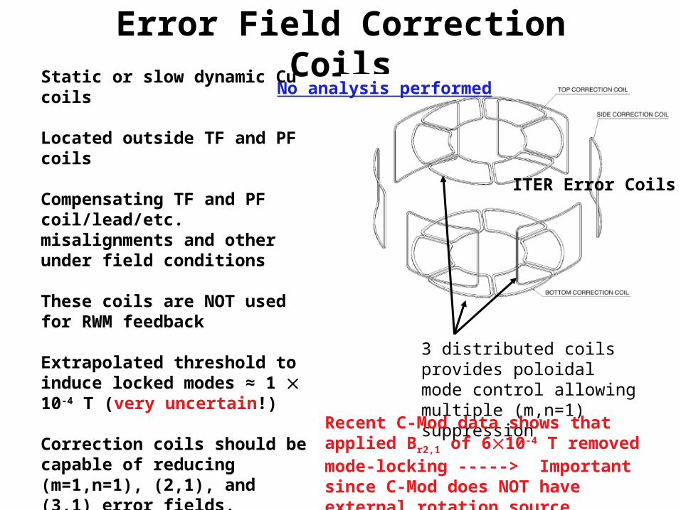
Error Field Correction CoilsStatic or slow dynamic Cu coils
Located outside TF and PF coils
Compensating TF and PF coil/lead/etc. misalignments and other under field conditions
These coils are NOT used for RWM feedback
Extrapolated threshold to induce locked modes ≈ 1 10-4 T (very uncertain!)
Correction coils should be capable of reducing (m=1,n=1), (2,1), and (3,1) error fields, simultaneously
And provide factor of ≈ 5 reduction in net error field Br2,1
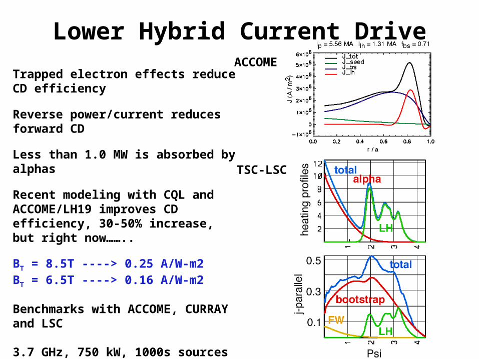
3.7 GHz, 750 kW, 1000s sources availableITER estimate for 5 GHz, 1.0 MW, CW sources was 1.15 euro/watt
ACCOME
TSC-LSC
Electron Cyclotron
=ce=170 GHz
pe=ce
Rays are bent as they approach = pe
Rays are launched with toroidal directionality for CD
Frequency of 170 GHz to utilize ITER R&D
LFS, O-mode, fundamental
FIRE has high density and high fieldCutoff of EC when = pe
AT-modeLower BT = 6.5 T
LFS deposition implies trapping reduction of CD, however, Ohkawa effect provides more CD than standard EC
Current required, scaled as IpN2 from
DIII-D and ASDEX-U expts for (3,2) mode----> drive 200 kA to suppress from saturated state----> requires 100 MW!
Electron Cyclotron
Bt=6.5 T
Bt=7.5 T
Bt=8.5 T
Ro Ro+a
fce=182 fce=142
fce=210 fce=164
fce=190fce=238
170 GHz
200 GHz
qmin(3,1)
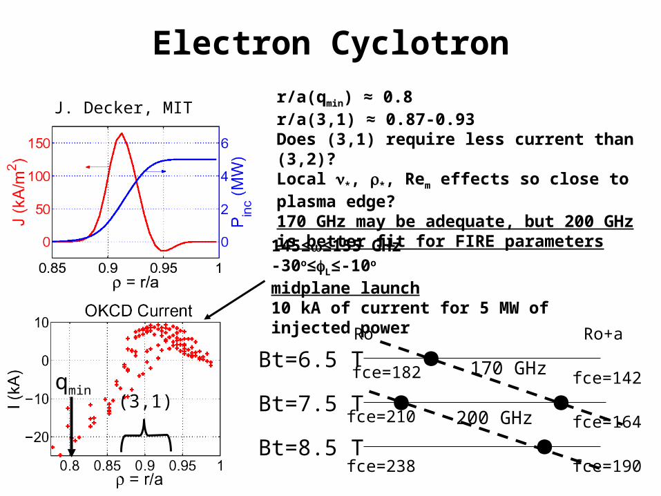
J. Decker, MIT
145≤≤155 GHz-30o≤L≤-10o
midplane launch10 kA of current for 5 MW of injected power
r/a(qmin) ≈ 0.8r/a(3,1) ≈ 0.87-0.93Does (3,1) require less current than (3,2)?Local *, *, Rem effects so close to plasma edge?170 GHz may be adequate, but 200 GHz is better fit for FIRE parameters
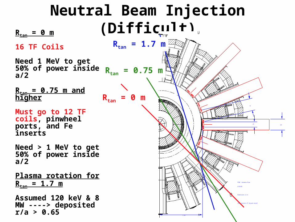
Neutral Beam Injection (Difficult)
.32
.71
2.56
.65
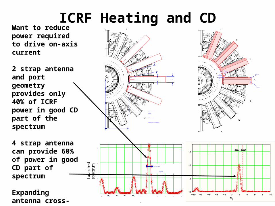
FIRE Antenna Plan
4/24/01
Dimensions in m
1999 version of Vacuum vessel
Rtan = 0 m
Rtan = 0.75 m
Rtan = 1.7 m
Rtan = 0 m
16 TF Coils
Need 1 MeV to get 50% of power inside a/2
Rtan = 0.75 m and higher
Must go to 12 TF coils, pinwheel ports, and Fe inserts
Rapid shutdown Massive gas puff Killer pellet or liquid jet Disruption/VDE
Pellet sizes 3-4 mm
Require ≈ 1-21021 tritons/s for FIRE H-mode---> 0.1-0.2 g T injected per shot (20 s)---> 5% of injected tritium consumed
HFS launch, limited to 125 m/s (test actually performed at ORNL to find pellet speed limit)
LFS and VL can reach much higher velocities
VL is at major radius, therefore not expected to provide improvement over LFS
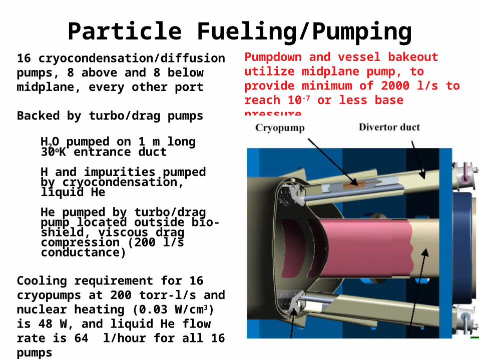
Particle Fueling/Pumping16 cryocondensation/diffusion pumps, 8 above and 8 below midplane, every other port
Backed by turbo/drag pumps
H2O pumped on 1 m long 30oK entrance duct
H and impurities pumped by cryocondensation, liquid He
He pumped by turbo/drag pump located outside bio-shield, viscous drag compression (200 l/s conductance)
Cooling requirement for 16 cryopumps at 200 torr-l/s and nuclear heating (0.03 W/cm3) is 48 W, and liquid He flow rate is 64 l/hour for all 16 pumps
Regeneration is done into the turbo/drag pumps
Pumpdown and vessel bakeout utilize midplane pump, to provide minimum of 2000 l/s to reach 10-7 or less base pressure
Particle Fueling/Pumping
V = 125 m/sParks, 2003
WHIST simulation of FIRE H-mode discharge (Houlberg)
Assume uniform pellet depositionObtains some density peaking with sufficient pumping
MHD StabilitySawtooth H-mode
Unstable to internal kink, r/a(q=1) ≈ 0.35 m-----> coupling to other global modes?
Porcelli sawtooth model (WMHD+ WKO+ Wfast), incorporated into TSC indicates effect on fusion performance is weak
Pedestal/bootstrap broadens j profileRapid reheat of sawtooth volume
-particles providing stabilization
Complete stabilization would require RFCD since FIRE does not have high energy minority species
The q=1 surface can be removed from the plasma by
1.2 MA off-axis CDReduction of Ip to 6.0 MA
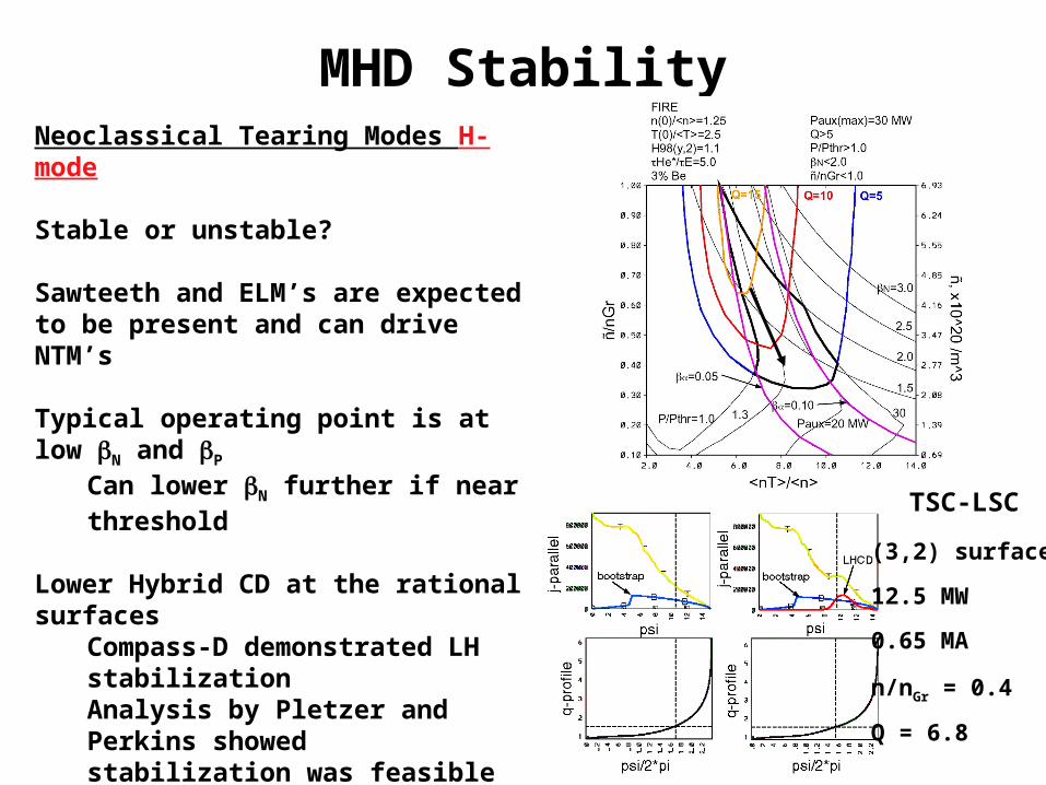
MHD StabilityNeoclassical Tearing Modes H-mode
Stable or unstable?
Sawteeth and ELM’s are expected to be present and can drive NTM’s
Typical operating point is at low N and P
Can lower N further if near threshold
Lower Hybrid CD at the rational surfacesCompass-D demonstrated LH stabilizationAnalysis by Pletzer and Perkins showed stabilization was feasible (PEST3)Lowers Q(=Pfus/Paux)
EC methods require high frequencies at FIRE field and densities ----> 280 GHz
TSC-LSC
(3,2) surface
12.5 MW
0.65 MA
n/nGr = 0.4
Q = 6.8
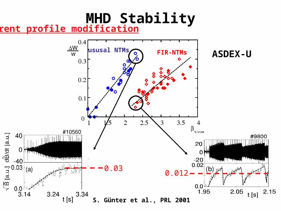
MHD Stability
FIR-NTMsususal NTMs
S. Günter et al., PRL 2001
0.030.012
ASDEX-U
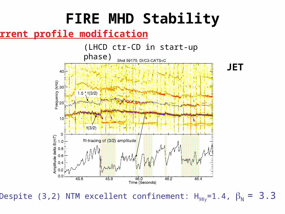
Current profile modification
FIRE MHD Stability
Despite (3,2) NTM excellent confinement: H98y=1.4, N = 3.3
(LHCD ctr-CD in start-up phase)
JET
Current profile modification
MHD StabilityIdeal MHD Stability H-mode
n=1 external kink and n=∞ ballooning modes H-mode
Stable without a wall/feedback
Under various profile conditions N ≤ 3
ballooning unstable in pedestal region depending on pedestal width and magnitude
Intermediate n peeling/ballooning modes H-mode
Unstable, primary candidate for ELM’s
Type I ELM’s are divertor lifetime limiting, must access Type II, III
Ploss/PLH ≈ 1.0-1.6 in flattop, not > 2 like many present experiments
FIRE has high triangularity (x = 0.7) in Double Null and high density
Active methods to reduce WELM include pellets, impurities, ergodization,…
Self-consistent ohmic/bootstrap equilibria
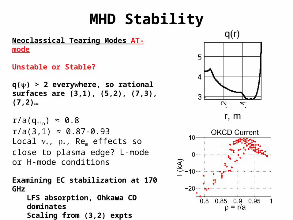
MHD StabilityNeoclassical Tearing Modes AT-mode
Unstable or Stable?
q() > 2 everywhere, so rational surfaces are (3,1), (5,2), (7,3), (7,2)…
r/a(qmin) ≈ 0.8r/a(3,1) ≈ 0.87-0.93Local *, *, Rem effects so close to plasma edge? L-mode or H-mode conditions
Examining EC stabilization at 170 GHzLFS absorption, Ohkawa CD dominatesScaling from (3,2) expts indicates high power ----> early detection required
LH using two spectra, one for bulk CD and other for NTM suppression
MHD StabilityIdeal MHD Stability AT-mode
n= 1, 2, and 3…external kink and n = ∞ ballooning modes
n = 1 stable without a wall/feedback for N < 2.5-2.8n = 2 and 3 have higher limits without a wall/feedback
Ballooning stable up to N < 6.0, unstable in pedestal region of H-mode edge plasmas.
RWM stabilization with feedback coils, VALEN analysis indicates 80-90% of ideal with wall limit for n=1
n = 1 stable with wall/feedback to N’s around 5.0-6.0
n = 2 and 3 appear to have lower N limits in presence of wall, possibly blocking access to n = 1 limits
Intermediate n peeling/ballooning modes–Unstable under H-mode edge conditions
Gro
wth
Rat
e, /s
N
N=4.2
Bialek, Columbia Univ.
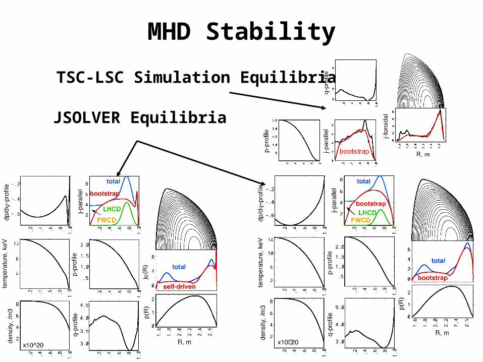
MHD Stability
JSOLVER Equilibria
TSC-LSC Simulation Equilibria
MHD Stability
Other MHD Issues H-mode and AT-mode
Alfven eigenmodes and energetic particle modes
Snowmass assessment indicated stable for H-mode, although access to shorter pulse high Pfus plasmas should destabilize
AT-mode not analyzed
Error fields from coil misalignments, etc. ----> install Cu window coils outside TF coil, stationary to slow response
FIRE does not have an external source of rotation
Transport, sheared rotation
Resistive instabilities, sheared to bulk rotation
RWM, bulk rotation
Plasma self-rotation (C-Mod), is it sufficient for some stabilization
Disruption ModelingComments
frequency 10-30% 30% plasma development, 10% for repetitive operation
number 300 (900) 300 at maximum Wmag and Wth
thermal energy 35 MJ
themal quench duration 0.2 ms (0.1-0.5) single or multi-step quench
fraction of Wth to divertor 80-100% (or ver low for mitigation) conduction to targets, 2-1 asymmetry
fraction of Wth to first wall/baffle < 30% (or nearly 100% for mitigation) radiation
inside to outside divertor split 5 to 1 need data on DN
poloidal localization 3x typical SOL width(1x to 10x) this may not be reliable
magnetic energy 25 MJ
current quench 6 ms (2-600 ms)
Ip decay rate 1 MA/ms typical, 3 MA/ms maximum
fraction of Wmag to FW by radiation 80-100% peaking factor of 2
fraction of Wmag to FW by conduction 0-20%
VDE frequency 10% of disruptions uncertain due to up-down symmetry
halo current fraction, Ihalo/Ip 0.4 (0-0.5)
halo current toroidal peaking 2 (1.2-4)
(Ihalo/Ip) TPF 0.5 typical maximum experimental data boundary is 0.75
runaway electron current 50% of Ip Highly uncertain, high density in FIRE makes this much weaker
localization of runaway deposition < 1 m2 PFC and wall alignment
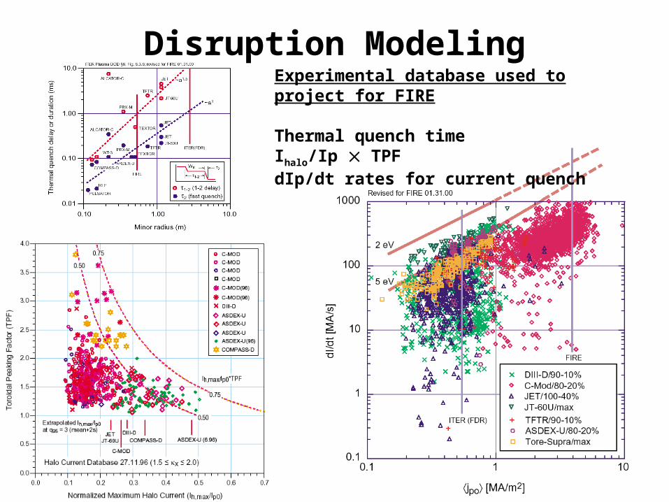
Disruption ModelingExperimental database used to project for FIRE
Thermal quench timeIhalo/Ip TPFdIp/dt rates for current quench
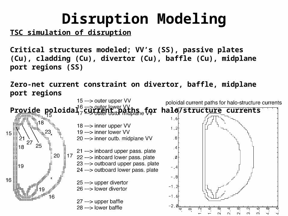
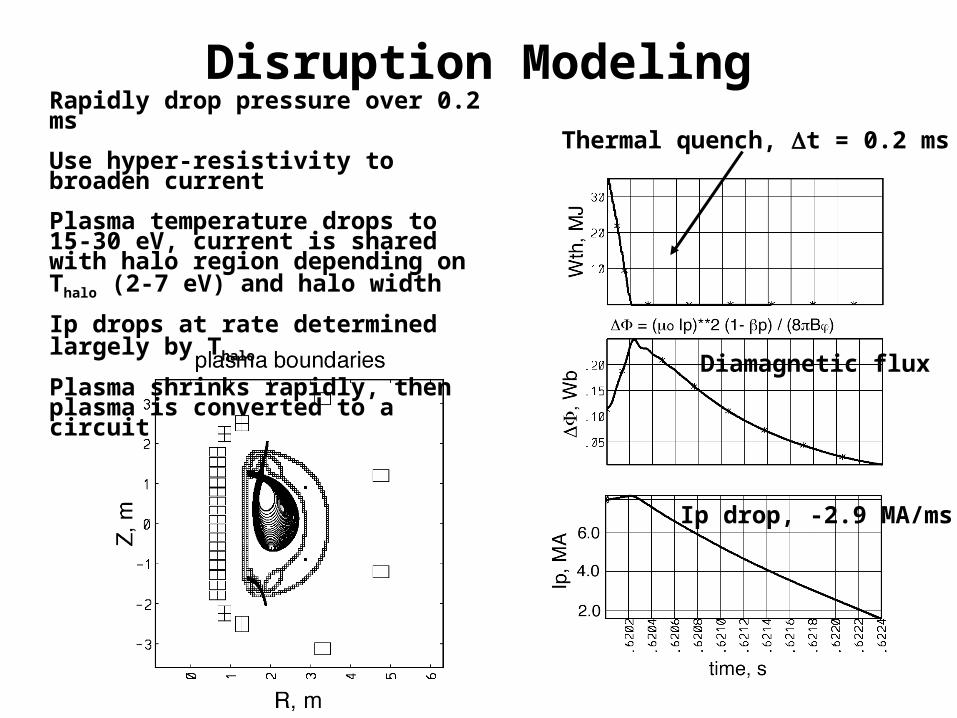
Disruption ModelingTSC simulation of disruption
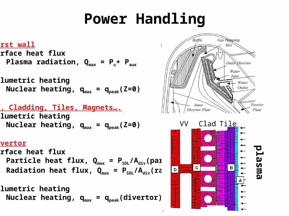
Critical structures modeled; VV’s (SS), passive plates (Cu), cladding (Cu), divertor (Cu), baffle (Cu), midplane port regions (SS)
Zero-net current constraint on divertor, baffle, midplane port regions
Provide poloidal current paths for halo/structure currents
Disruption Modeling
Thermal quench, t = 0.2 ms
Ip drop, -2.9 MA/ms
Diamagnetic flux
Rapidly drop pressure over 0.2 ms
Use hyper-resistivity to broaden current
Plasma temperature drops to 15-30 eV, current is shared with halo region depending on Thalo (2-7 eV) and halo width
Ip drops at rate determined largely by Thalo
Plasma shrinks rapidly, then plasma is converted to a circuit
Disruption ModelingTSC simulation produces for Engr. analysis
Toroidal structure currents, fields and forces
Poloidal structure current, fields, and forces
Plasma toroidal currents on a grid
Halo/poloidal plasma currents at structure interfaces
Global plasma and PF coil data
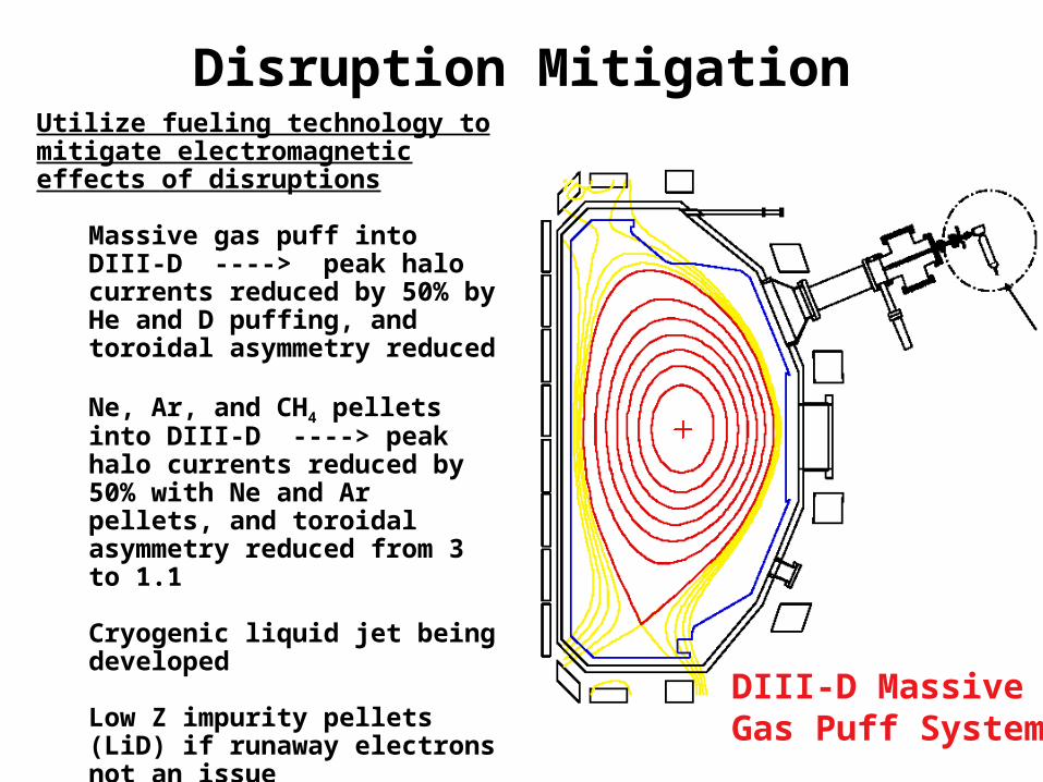
Disruption MitigationUtilize fueling technology to mitigate electromagnetic effects of disruptions
Massive gas puff into DIII-D ----> peak halo currents reduced by 50% by He and D puffing, and toroidal asymmetry reduced
Ne, Ar, and CH4 pellets into DIII-D ----> peak halo currents reduced by 50% with Ne and Ar pellets, and toroidal asymmetry reduced from 3 to 1.1
Cryogenic liquid jet being developed
Low Z impurity pellets (LiD) if runaway electrons not an issue
Snowmass assessment indicated large radiated power to FW could cause Be melting
DIII-D MassiveGas Puff System
FIRE Transport and ConfinementEnergy Confinement Database
0.58Ra0.81 (2000) ----> 26 MW in flattopPLH(MW) = 2.58Meff
-1BT0.60nL20
0.70R0.83 a1.04 (2002) ----> 18.5-25 MW in flattop
DN has less or equal PLH compared to favored SN (Carlstrom, DIII-D; NSTX; MAST)
H-L Transition & ELM’s Ploss > PLH although hysterisis exists in dataType I ELM’s typically require Ploss > 1.( )PLH, expts typically > 2PLH
Type II ELM’s require strong shaping, higher density, DN ---> reduced Pdiv, H98=1Type III ELM’s, near Ploss ≈ PLH, or high density, reduced H98
Active methods ----> pellets, gas puffing, impurity seeding, ergodization
Pedestal Physics and ELM’sPedestal physics
Intermediate n peeling/ballooning modes----> ballooning destabilized by high p’ and low j----> peeling modes destabilized by high j and low p’
Stronger shaping raises pped
Stability analysis distinguishes nped and Tped through *
ped (nped/Tped2) ---> jBS
Higher nped leads to mode envelope narrows and lowers jBS ---> smaller WELM
weak shaping strong shaping
ELITE projections for FIRE
Pedestal Physics and ELM’sType I ELM trends
Reduced WELM/Wped with increasing *ped ----> inconsistent with higher Tped for
high Q
Reduced WELM/Wped with increasing ||i ----> inconsistent with higher Tped for
high Q
WELM/Wped correlated with Tped/Tped as nped varied, very little change in Nped/Nped
Type II ELM’sASDEX-U with DN and high n ----> H98 = 1-1.2 and reduction in divertor heat flux by 3
JET with high and high n ----> mixed Type I+II, no reduction in confinement and 3 reduction in ELM power loss
Pin
Wth
Prad
PELM
JET
Pedestal Physics and ELM’s
Active methods for ELM mitigation
JET argon seeding in Type I, frad > 0.65, H98 ≈ 1, n/nGr> 0.7, Q div reduced by 2Type III, frad > 0.7, H98 ≈ 0.7-0.9, n/nGr > 0.7
Pellets that trigger ELMs, avoiding large infrequent Type I ELMs
Ergodization of plasma edge region, use coils to produce high (m,n) field that perturb only ELM region
JET
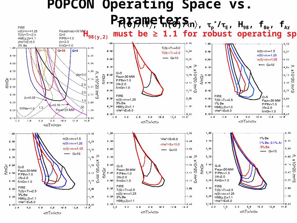
POPCON Operating Space vs. ParametersT(0)/T, n(0)/n, p
*/E, H98, fBe, fAr
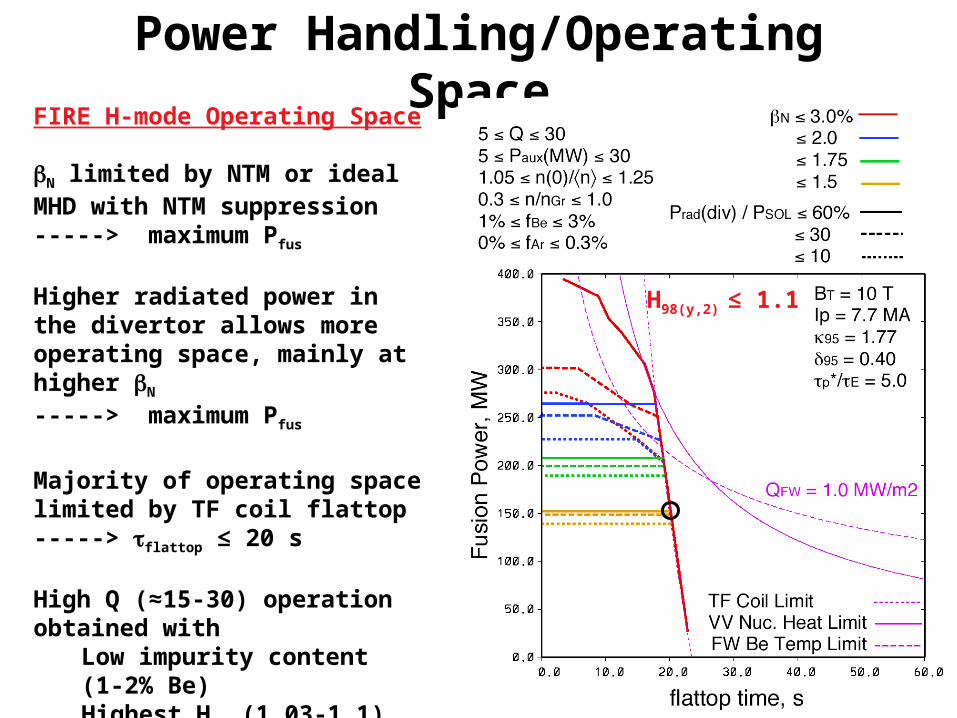
H98(y,2) must be ≥ 1.1 for robust operating space
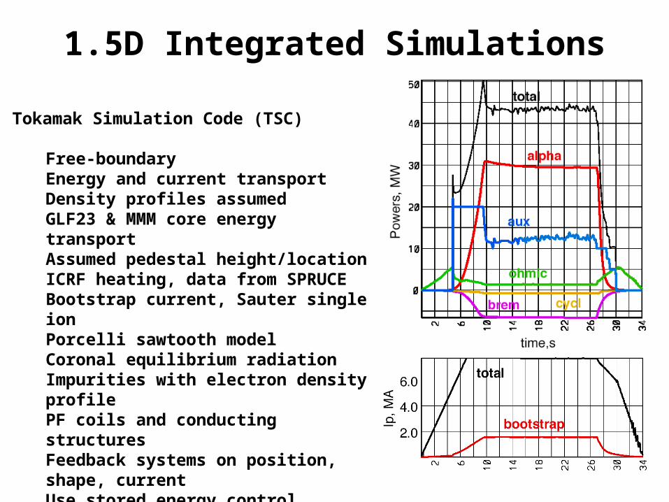
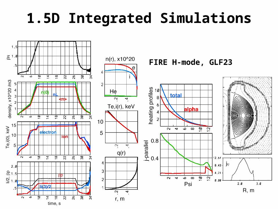
1.5D Integrated Simulations
Tokamak Simulation Code (TSC)
Free-boundaryEnergy and current transportDensity profiles assumedGLF23 & MMM core energy transportAssumed pedestal height/locationICRF heating, data from SPRUCEBootstrap current, Sauter single ionPorcelli sawtooth modelCoronal equilibrium radiationImpurities with electron density profilePF coils and conducting structuresFeedback systems on position, shape, currentUse stored energy control
Snowmass E2 simulations for FIRECorsica, GTWHIST, Baldur, XPTOR
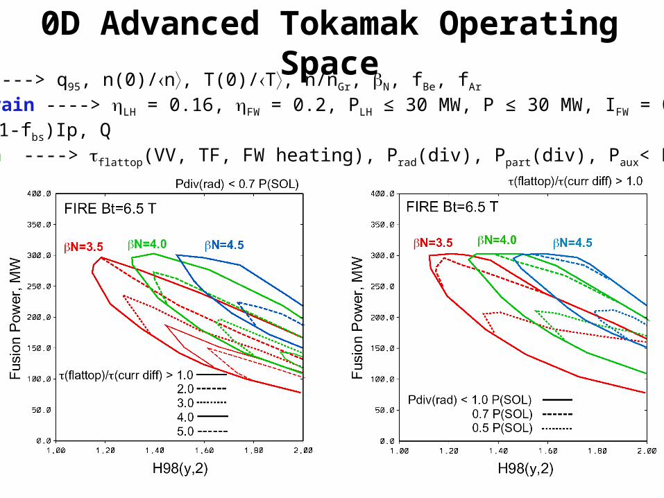
Observations from 0D Analysis for Burning Plasma AT
• In order to provide reasonable fusion gain Q≥5, can’t operate at low density to maximize CD efficiency
• Density profile peaking is beneficial (pellets or ITB), since broad densities increase required H98 and PCD
• Access to high density relative to Greenwald density, in combination with high bootstrap current fraction gives the lowest required H98
• H98 ≥1.4 are required to access flattop/curr diff > 3, however, the ELMy H-mode scaling law is known to have a degradation that is not observed on individual experiments
• Radiative core/divertor solutions are a critical area for the viability of burning AT experiments due to high P+PCD, suggesting impurity control techniques
• Access to higher radiated power fractions in divertor enlarge operating space significantly
• Access to higher flattop/j decreases at higher N, higher BT, and higher Q, since flattop set by VV nuclear heating
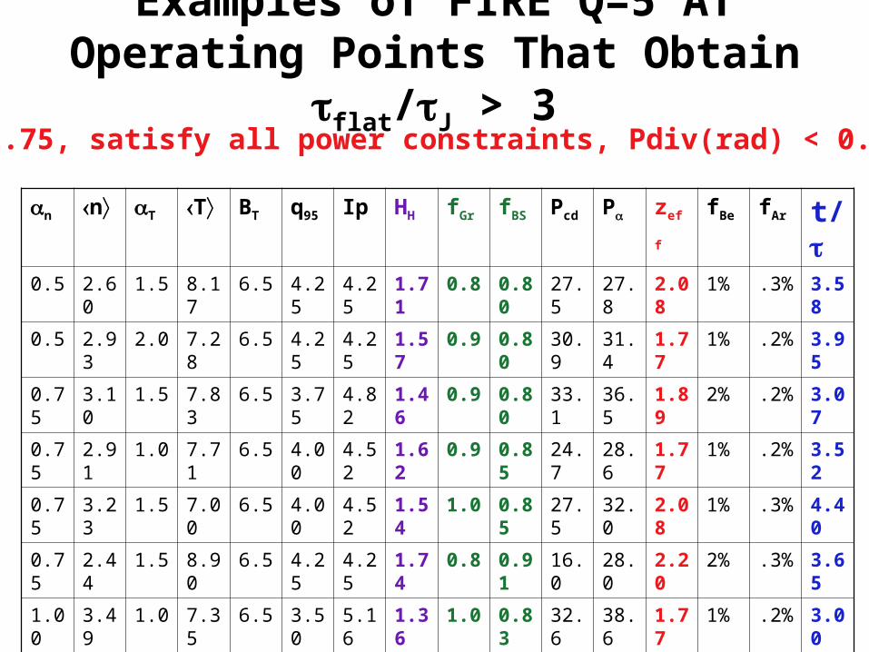
Examples of FIRE Q=5 AT Operating Points That Obtain flat/J > 3
n n T T BT q95 Ip HH fGr fBS Pcd P zeff fBe fAr t/
HH < 1.75, satisfy all power constraints, Pdiv(rad) < 0.5 P(SOL)
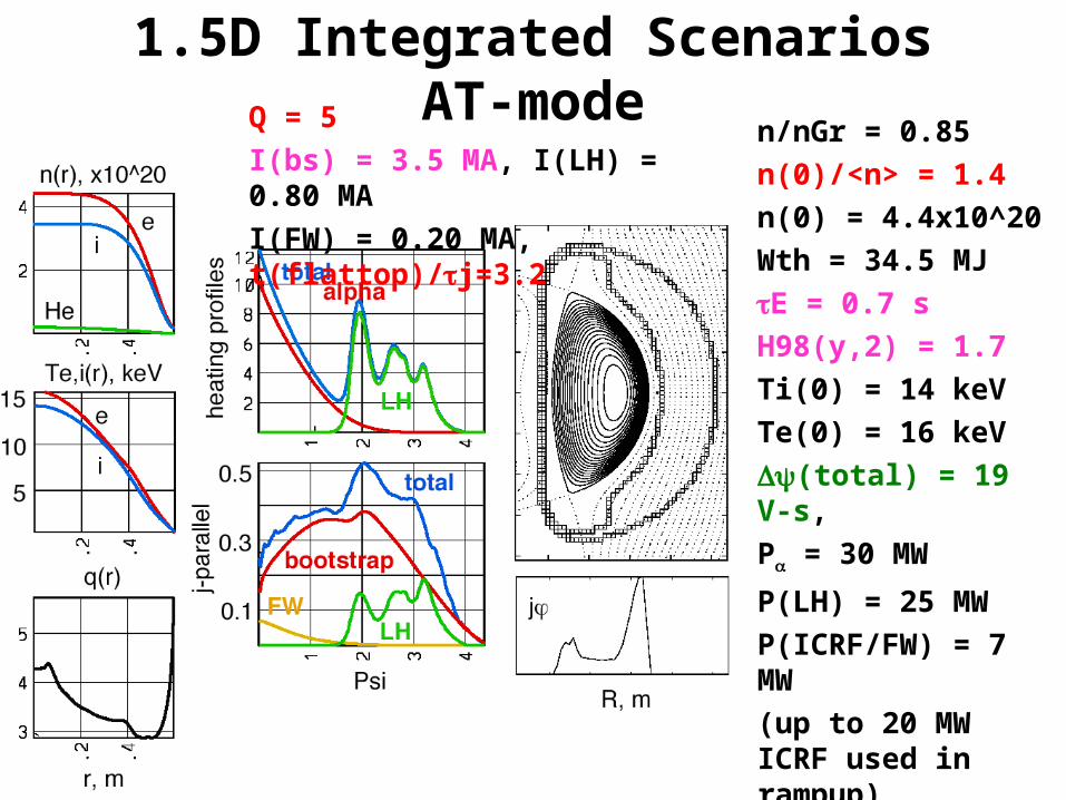
1.5D Integrated Simulations AT-modeIp=4.5 MA Bt=6.5 T N=4.1 t(flat)/j=3.2 I(LH)=0.80P(LH)=25 MW
fBS=0.77 Zeff=2.3 q(0) =4.0 q(min) = 2.75 q(95) = 4.0 li = 0.42, = 4.7%, P = 2.35
1.5D Integrated Scenarios AT-mode
t = 12-41 s
1.5D Integrated Scenarios AT-moden/nGr = 0.85
n(0)/<n> = 1.4
n(0) = 4.4x10^20
Wth = 34.5 MJ
E = 0.7 s
H98(y,2) = 1.7
Ti(0) = 14 keV
Te(0) = 16 keV
(total) = 19 V-s,
P = 30 MW
P(LH) = 25 MW
P(ICRF/FW) = 7 MW
(up to 20 MW ICRF used in rampup)
P(rad) = 15 MW
Zeff = 2.3
Q = 5
I(bs) = 3.5 MA, I(LH) = 0.80 MA
I(FW) = 0.20 MA, t(flattop)/j=3.2
Perturbation of AT-mode Current Profile
5 MW perturbation to PLH
Flattop time is sufficient to examine CD control
t = 12 st = 25 s
t = 25 st = 41 s
Conclusions
• The FIRE device design provides sufficient/flexible/relevant operating space to examine burning plasma physics– Sufficient to provide burning conditions (Q ≥ 10 inductive and Q ≥ 5
AT, does not preclude ignition)– Flexible to accommodate uncertainty and explore various physics
regimes– Relevant to power plant plasma physics and engineering design
• The subsystems on FIRE, within their operating limits, are suitable to examine burning plasma physics ----> subject to R&D in some cases– Auxiliary heating/CD– Particle fueling and pumping– Divertor/baffle and FW PFC’s– Magnets– Diagnostics
Conclusions• Burning plasma conditions can be accessed and studied
in both standard H-mode and Advanced Tokamak modes. The range of AT performance has been expanded significantly since Snowmass– FIRE can reach 1-5 j, and examine current profile control– Design improvement to FW tiles could extend flattop times
further – FIRE can reach 80-90% of ideal with wall limit, with RWM
feedback– FIRE can reach high IBS/IP (77% in 1.5D simulation)– Identified that radiative mantle/divertor solutions significantly
expand operating space– FIRE will pursue Fe shims for AT operation
• The physics basis for FIRE’s operation is based on current experimental and theoretical results, and projections based on these continue to provide confidence that FIRE will achieve the required burning plasma performance
Issues/Further Work
• Magnets– Ripple reduction, design Fe shims for AT mode
– Continue equilibrium analysis
– Complete plasma breakdown and early startup
– Complete internal control coil analysis
– RWM coil design/integration into port plugs, time dependent analysis