33
Andrew Carmean, P.E., LEED AP Mechanical Engineer 325 CES/CENPE Fire Protection Analysis of F‐35 Fuel Cell Maintenance Hangar

Andrew Carmean, P.E., LEED APMechanical Engineer
325 CES/CENPE
Fire Protection Analysis ofF‐35 Fuel Cell Maintenance Hangar

Overview• Facility Overview• Prescriptive Design Analysis
• Life Safety• Detection and Notification• Fire Suppression
• Performance Based Evaluation• Goals• Design Fire• Performance Criteria• Evaluation
• Conclusion and Recommendations

• International Building Code 2009• Engineering Technical Letter (ETL) 02-15: Fire Protection
Engineering Criteria – New Aircraft Facilities• UFC 3-600-01 Fire Protection Engineering For Facilities• NFPA 101: Life Safety Code• NFPA 72: National Fire Alarm And Signaling Code• NFPA 13: Standard For The Installation Of Sprinkler Systems• NFPA 11: Standard For Low-, Medium-, And High-expansion Foam
Relevant Codes and Standards

Facility Overview

Life Safety

Space UseOccupancyClassification
(LSC)Color Code
Hangar Bay Special Industrial
Utility Rooms Business
Maintenance Area Business
Tool Crib Business
Storage Business
Laundry Room Business
Rest Rooms Business
Exit Corridors Business
Office Space Business
Training / Break Room Business
Life Safety – Occupancy Classification

Occupant Load
DescriptionArea (SF)
Occupant Load Factor
Occupant Load
Egress Capacity
Hangar Bays 16240 100 162 800Business Area 2490 100 25
160Training Area (net) 547 15 36Maintenance Area 2745 100 27 320

Arrangement of Means of Egress
Area Common Path
Common Path Limit Dead‐End Dead‐End
LimitTravel
DistanceTravel Distance
Limit
Hangar Bay 1 NA 100 NA 50 83 400Hangar Bay 2 NA 100 NA 50 78 400
Office Space 40 100 0 50 59 300Maintenance Area 74 100 0 50 83 300

Protection

Detection and Notification

Detection

Notification

Fire Suppression

Space Use
Design Density and Design Area(NFPA 13)
(gpm/SF/SF)
Design Density and Design Area(ETL or UFC)(gpm/SF/SF)
Color Code and Design Actual Density/Demand Area
(gpm/SF/SF)
Hangar Bay 0.2/5000 0.2/5000 .02/5000
Maintenance Area, Utility Rooms, Tool Crib
0.2/1500 0.2/2500 0.2/3000
Office Space etc. 0.1/1500 0.1/1500 0.1/3000
Hazard Classification

NFPA 11 ETL 02‐15 Installed
Bay 1 Bay 2 Bay 1 Bay 2 Bay 1 Bay 2
Foam Discharge Rate (cfm) 21,221 17,697 43,558 33,554 51,494 33,971
Solution Rate (gpm) 317 265 652 502 770 508
Foam Concentrate Rate (gpm) 6 5 13 10 15 10
Quantity Foam (gal) 95 79 196 151 231 152
Water Rate (gpm) 311 259 639 492 755 498
Quantity Water (gal) 4,667 3,892 9,580 7,379 11,325 7,471
High Expansion Foam

Water Demand and Supply

Performance Based Evaluation

I. Life SafetyII. Property ProtectionIII. Minimize Environmental ImpactIV. Reduce Cost
Goals

I. Ignition SourceII. Fuel
I. Growth RateII. Fire SpreadIII. Quantity
III. Building CharacteristicsI. Structural Components
Design Fire

• Radiant Heaters• Lighting• Aerospace ground equipment
Ignition Source

• JP‐8 heat release rate is approximately 2.8 MW/m2
• Blanchat, T., et all, “Large‐Scale Open Pool Experimental Data Analysis and for Fire Model Validation and Development,” Sandia National Laboratories, Fire and Aerosol Sciences Department, 2008.
• JP‐8 flame spread rate is approximately 1.5 m/s at 71 ºC.• Leonard, J.T., et all, “Fire Hazards of Mixed Fuels on the Flight Deck,” Navy Technology
Center for Safety and Survivability, April 1992.
• JP‐8 stoichiometry closely approximates dodecane.• Mayfield, H.T., “JP‐8 Composition and Variability,” Armstrong Laboratory, Environmental
Research Division, May 1992.
• JP‐8 soot yield is approximately 0.08 % by weight. • Yan, Shihong, “Study of the Evolution of Soot from Various Fuels,” Departments of Chemical
engineering and Chemistry, University of Utah, Salt Lake City, Utah, April 2005.
Design Fire

Performance Criteria• Property Protection
• Beeson, H.D., et all, “Aircraft Composite material Fire Damage Assessment,” New Mexico Engineering Research Institute, University of New Mexico, September 1990.
• Yarlagadda, S., et all, “Post‐Fire Damage Assessment of a Composite Wingbox,” Air Force Research Laboratory, May 2004.
• Buchanan, A., (2002), Structural Design for Fire Safety. • Environmental Impact
• Choose foam agents that• Minimize biological oxygen demand• Minimize toxic exposure to aquatic life
• Cost Reduction• Choose foam agents that minimize cost
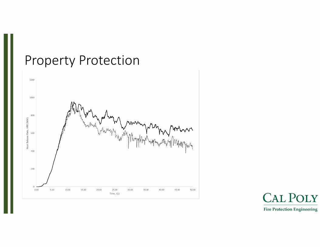
Property Protection

Property Protection

Property Protection

Property Protection

Property Protection

Property Protection

Environmental Impact
AFFF High Expansion Foam
BOD (mg/l) 7,818 18,389
LC50 (mg/l) 37,800 1,100

NFPA 11 ETL 02‐15 Installed
Bay 1 Bay 2 Bay 1 Bay 2 Bay 1 Bay 2
Foam Discharge Rate (CFM)
21221 17697 43558 33554 51494 33971
Solution Rate (gpm) 317 265 652 502 770 508
Foam Concentrate Rate (gpm)
6 5 13 10 15 10
Quantity Foam Concentrate (gal)
95 79 196 151 231 152
Water Rate (gpm) 311 259 639 492 755 498
Quantity Water (gal) 4667 3892 9580 7379 11325 7471
Cost Reduction

Cost Reduction

• Change wet‐pipe sprinklers to foam‐water or AFFF sprinklers system
• Modify Adjustable retard switch timing• Add UV/IR Detection• Reduce Over‐design• Ensure proper training
Conclusion and Recommendations

The End


![f35-frosh-sem-3d-models-2d-images.ppt - UCSBparhami/pres_folder/f35...Microsoft PowerPoint - f35-frosh-sem-3d-models-2d-images.ppt [Compatibility Mode] Author: parha Created Date:](https://static.documents.pub/doc/80x56/6020bbfbc069bf413e212b45/f35-frosh-sem-3d-models-2d-ucsb-parhamipresfolderf35-microsoft-powerpoint.jpg)


