First Co. Certified Reference Number: Print Date: Void Date: Outdoor Unit Manufacturer: Outdoor Unit Model Number: First Co. Indoor Model Number: Cooling Capacity (MBTUH): EER (Cooling) SEER (Cooling): Heating Capacity (MBTUH): HSPF (Heating): First Co. Certificate of Product Ratings First Co. certifies that the capacity and SEER values shown are calculated using the methodology in Section 430.23(M) of 10CFR Part 430. The calculation procedure utilizes test data collected in accordance with ANSI/AHRI 210/240-2008. DOE Requirement Effective July 5, 2011, the U.S. Department of Energy (DOE) issued a Final Rule (10 CFR Parts 429-431) that expands the existing certification, compliance, and enforcement requirements for all covered products, including Residential and Commercial HVAC products. As part of the Final Rule, all efficiency information for covered prod- ucts must be on file with DOE. All First Co. ratings have been submitted to DOE. Certification Vertification The above rating information can be verified on either of the following web sites: First Co.: ratings.firstco.com DOE: www.regulations.doe.gov/certification-data F106882 CARRIER 37HXX 25HCE436C*030* 34.0 12.00 14.00 8/7/2017 07/01/2018 34.8 8.2
Transcript
First Co. Certified Reference Number: Print Date:
Void Date:
Outdoor Unit Manufacturer:
Outdoor Unit Model Number:First Co. Indoor Model Number:
First Co. certifies that the capacity and SEER values shown are calculated using the methodology in Section 430.23(M) of 10CFR Part 430. The calculation procedure utilizes test data collected in accordance with ANSI/AHRI 210/240-2008.
DOE RequirementEffective July 5, 2011, the U.S. Department of Energy (DOE) issued a Final Rule (10 CFR Parts 429-431) that expands the existing certification, compliance, and enforcement requirements for all covered products, including Residential and Commercial HVAC products. As part of the Final Rule, all efficiency information for covered prod-ucts must be on file with DOE. All First Co. ratings have been submitted to DOE.
Certification VertificationThe above rating information can be verified on either of the following web sites:First Co.: ratings.firstco.comDOE: www.regulations.doe.gov/certification-data
F106882
CARRIER
37HXX25HCE436C*030*
34.012.0014.00
8/7/2017
07/01/2018
34.88.2
takako.baker
FC-1/OHP-9
First Co. Certified Reference Number: Print Date:
Void Date:
Outdoor Unit Manufacturer:
Outdoor Unit Model Number:First Co. Indoor Model Number:
First Co. certifies that the capacity and SEER values shown are calculated using the methodology in Section 430.23(M) of 10CFR Part 430. The calculation procedure utilizes test data collected in accordance with ANSI/AHRI 210/240-2008.
DOE RequirementEffective July 5, 2011, the U.S. Department of Energy (DOE) issued a Final Rule (10 CFR Parts 429-431) that expands the existing certification, compliance, and enforcement requirements for all covered products, including Residential and Commercial HVAC products. As part of the Final Rule, all efficiency information for covered prod-ucts must be on file with DOE. All First Co. ratings have been submitted to DOE.
Certification VertificationThe above rating information can be verified on either of the following web sites:First Co.: ratings.firstco.comDOE: www.regulations.doe.gov/certification-data
F106728
CARRIER
25HXX25HBC524A*030*
23.411.2014.00
8/7/2017
07/01/2018
24.08.2
takako.baker
FC-2/OHP-10
HXX(-C) SeriesHorizontal Recessed
Ceiling Fan Coil1.5 - 3.0 Tons Cooling or Heat Pump
0 - 10 kW Electric Heat
These recessed ceiling fan coils are designed for use with today's higher efficiency split-system condensing units and heat pumps. High efficiency ECM type motors are standard in all HXX series fan coils.
The base HXX fan coil is an open blower type (non-enclosed) fan coil. It is also available with either a field or factory installed enclosure, with both options including your choice of either a louvered or solid ceiling panel. For HXX fan coils factory installed within an enclosure, add "-C" after the kW in the model number. For instance, ordering model 19HXX5-C R410 TXV, will include an 19HXX5 R410 TXV fan coil factory installed in a number 9EHX01 enclosure and your choice of either a solid or louvered panel (see "Enclosures with Ceiling Panels" on P. 3). A "cap kit" is also available when the HXX is installed above a ceiling, rather than recessed (see P. 4).
Compatible outdoor units: First Co's customer is ultimately responsible for confirming which fan coil models are com-patible with selected outdoor units. To determine certified indoor/outdoor matches, go to www.firstco.com or contact the factory.
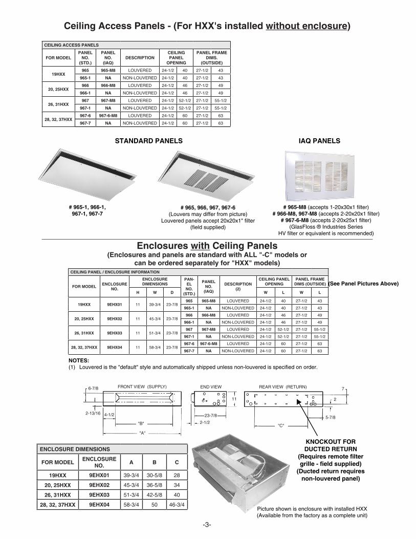
Standard Features: • HighefficiencyECMmotor • Drainpanhas3/4"NPTprimaryandsecondary(overflow) fittings • 240Vmotor,24Vcontrol • Factoryinstalledelectricheat(upto10kW)(except0kW models) • Highlyefficientcoppertube/aluminumfincoolingcoilwith factoryinstalledR-410ATXV(non-bleedtype) • Insulatedandcoatedgalvanizedsteeldrainpan,sloped for positive drainage • EffectiveJanuary2016,Cabinetairleakageisnomorethan 2%whentestedinaccordancewithASHRAE193. Optional Features: • Attractiveoff-whitereturnair/accesspanelwith captive screws. They can be used with either the non- enclosed HXX or the HXX with a field or factory installed enclosure. • IAQ filter panels (see P. 3) • Fieldinstalledenclosure.Allenclosuresarefully insulated and include cutouts for optional ducted return air.Ductedreturnairoptionrequiresremotefilter-grille. • Heatpumpkit-requiredforallHXX models having electric heat (#942-1).(P.2) • Condensateoverflowswitch(#SS3) (field installed) • Enclosure"CapKit"-forabovetheceilinginstallation(P.4)
Optional Access Panel(non-louvered shown)
(see P. 3 for information)
HXX Fan Coil
Optional Insulated Enclosure(see P. 3 for information)
Matching Access Panel for Enclosure(non-louvered shown)
SUCTION LINE5/8 SWEAT: 19HXX7/8 SWEAT: 25-37HXXLIQUID LINE - 3/8 SWEAT
Approved for installation with 0" clearance to combustible
materials
Note: Heat pump kit must be field installed for all HXX models withelectricheat.0kWmodelsdonotrequirekit.Contact the factory for compatibility match with condensing unit.
(1) Add .05 static when enclosure is used.
(See P. 4 for Model Numbers)
PHYSICAL DIMENSIONS
MODEL A B C D
19HXX 37-1/4 34-11/16 30 6-1/2
20,25HXX 43-1/4 40-11/16 36 6-1/2
26,31HXX 49-1/4 46-11/16 42 6-1/2
28,32,37HXX 56-1/4 53-11/16 49 6-1/2
In keeping with its policy of continuous progress and product improvement, First Co. reserves the right to make changes without notice. Maintenance for all First Co. products is available under "Product Maintenance" at www.firstco.com.
-2-
BLOWER DATA
UNIT MODEL
MOTORHP
(240V)
SPEEDTAP
MOTORBHP
NOM.AMPS
CFM vs. EXTERNAL STATIC PRESSURE
0.00 0.05 0.10 0.15 0.20 0.25 0.30 0.35 0.40
19HXX 1/2OPTIONALHIGH
STD.HIGHSTD.LOW
.16
.10
.08
1.2.08.07
800660590
765630555
730600520
695575495
660550470
620525445
580500420
535------
490------
20HXX 1/2OPTIONALHIGH
STD.HIGHSTD.LOW
.16
.10
.08
1.20.80.7
800650590
765625560
730600530
695575505
660550480
620525455
580500430
535------
490------
25HXX28HXX
1/2OPTIONALHIGH
STD.HIGHSTD.LOW
.30
.20
.16
2.11.51.0
970810720
950790690
930770660
910745645
890720630
870705615
850690600
825------
800------
26HXX 1/2OPTIONALHIGH
STD.HIGHSTD.LOW
.30
.20
.16
2.11.51.0
1010840750
980810715
950780680
925760655
900740630
880720615
860700600
840------
820------
31HXX 1/2OPTIONALHIGH
STD.HIGHSTD.LOW
.43
.32
.24
3.32.21.5
12301060920
11951015885
1160970850
1140945810
1120920770
1090875735
1060830700
995------
930------
32HXX 1/2OPTIONALHIGH
STD.HIGHSTD.LOW
.43
.32
.24
3.32.21.5
12801090950
12451050920
12101010890
1180985855
1150960820
1115930790
1080900760
1025------
970------
37HXX 1/2OPTIONALHIGH
STD.HIGHSTD.LOW
.51
.43
.32
4.03.32.2
143012601110
140012251080
137011901050
135511601025
132011301000
12951115970
12701100940
1220------
1170------
HEAT PUMP KIT (FIELD INSTALLED)
PARTNO. DESCRIPTION
942-1 KITFORHXXMODELSWITHELECTRICHEAT
PERFORMANCE DATA
UNIT MODELNOM. CFM
NOM. COOL BTUH
HEAT (1) TOTAL AMPSMIN. CIR.
AMPACITYMAX FUSE
kW BTUH 208V 240V 208V 240V 208V 240V
19HXX20HXX
-0-3-5-6-8-10
600 18,000
- - -3568
10
- - -10,20017,00020,50027,30034,100
4.315.222.426.033.240.4
4.316.825.229.337.746.0
---1928334251
---2132374758
---2030355060
---2535405060
25HXX26HXX28HXX
-0-3-5-6-8-10
800 24,000
- - -3568
10
- - -10,20017,00020,50027,30034,100
4.315.222.426.038.240.4
4.316.825.229.337.746.0
---1928334251
---2132374758
---2030355060
---2535405060
31HXX32HXX
-0-3-5-6-8-10
1000 30,000
- - -3568
10
- - -10,20017,00020,50027,30034,100
4.315.222.426.033.240.4
4.316.825.229.337.746.0
---1928334251
---2132374758
---2030355060
--- 2535405060
37HXX
-0-3-5-6-8-10
1200 36,000
- - -3568
10
- - -10,20017,00020,50027,30034,100
4.315.222.426.033.240.4
4.316.825.229.337.746.0
---1928334251
---2132374758
---2030355060
---2535405060
takako.baker
takako.baker
takako.baker
takako.baker
takako.baker
FC-2
takako.baker
FC-1
6-7/8
4-1/22-13/16
"B"
"A"
23-7/8
2-1/2
11
"C"
5-7/8
2
7REAR VIEW (RETURN)END VIEWFRONT VIEW (SUPPLY)
Ceiling Access Panels - (For HXX's installed without enclosure)
Enclosures with Ceiling Panels(Enclosures and panels are standard with ALL "-C" models or
can be ordered separately for "HXX" models)
Picture shown is enclosure with installed HXX (Available from the factory as a complete unit)
UNCASED (NO ENCLOSURE) FACTORY INSTALLED ENCLOSURE
(ALL WITH FACTORY INSTALLED R410A TXV)
(ALL WITH FACTORY INSTALLED R410A TXV)
MODEL SIZE (BTU) MODEL MODEL
18,000 19HXX(*)R410TXV 19HXX(*)-CR410TXV
18,000 20HXX(*)R410TXV 20HXX(*)-CR410TXV
24,000 25HXX(*)R410TXV 25HXX(*)-CR410TXV
24,000 26HXX(*)R410TXV 26HXX(*)-CR410TXV
24,000 28HXX(*)R410TXV 28HXX(*)-CR410TXV
30,000 31HXX(*)R410TXV 31HXX(*)-CR410TXV
30,000 32HXX(*)R410TXV 32HXX(*)-CR410TXV
36,000 37HXX(*)R410TXV 37HXX(*)-CR410TXV
MODEL NUMBERS:
HXX(-C) Series1.5 through 3.0 tons
(*) = kW HEAT
All TXVs are approved for cooling only or heat pump operation (non-bleed type).
CAP KIT - FOR INSTALLATION ABOVE A SUSPENDED CEILING
PART NO. FITS ENCLOSURE NO. FOR UNIT MODEL
9PHX01 9EHX01 19HXX-C
9PHX02 9EHX02 20,25HXX-C
9PHX03 9EHX03 26,31HXX-C
9PHX04 9EHX04 28,32,37HXX-C
NOTES:1. Cap kit is an insulated panel that covers the entire bottom openingoftheenclosure(requiresductedreturn)2. Capkitwouldbeusedinlieuoftheceilingpanel
-4-
Product Data
25HCE4Comfort™ 14 Heat Pumpwith Puronr Refrigerant1---1/2 to 5 Nominal Tons
Carrier heat pumps with Puronr refrigerant provide a collection offeatures unmatched by any other family of equipment. The25HCE4 has been designed utilizing Carrier’s non--ozonedepleting Puronr refrigerant.
NOTE: Ratings contained in this document are subject tochange at any time. Always refer to the AHRI directory(www.ahridirectory.org) for the most up--to--date ratingsinformation.
S Balanced refrigeration system for maximum reliability
DurabilityWeatherArmort protection package:S Solid, durable sheet metal construction
S Dense wire coil guard
S Baked--on powder paint
ApplicationsS Long--line -- up to 250 feet (76.20 m) total equivalent length, up
to 200 feet (60.96 m) condenser above evaporator, or up to 80 ft.
(24.38 m) evaporator above condenser (See Longline Guide for
more information.)
S Low ambient (down to --20_F/--28.9_C) with accessory kit
takako.baker
OHP-1
2
MODEL NUMBER NOMENCLATURE
1 2 3 4 5 6 7 8 9 10 11 12 13N N A A A/N N N N A/N A/N A/N N N
2 5 H C E 4 3 6 A 0 0 3 0
ProductSeries
ProductFamily Tier Major
Series SEER CoolingCapacity
GrilleVariations Open Open Voltage Minor
Series25 = HP H = RES HP C=Comfort E = Puron 4=14 SEER A=Dense Grille 0=Not
Defined0=NotDefined
3=208/230/15=208/230/36=460/3
0, 1, 2...
Use of the AHRI CertifiedTM Mark indicates amanufacturer’s participation in the program For verification of certification for individual products, go to www.ahridirectory.org.
*Units are rated with 25 ft (7.6 m) of lineset length. See Vapor Line Sizing and Cooling Capacity Loss table when using other sizes and lengths of lineset.Note: See unit Installation Instruction for proper installation.
VAPOR LINE SIZING AND COOLING CAPACITY LOSSAcceptable vapor line diameters provide adequate oil return to the compressor while avoiding excessive capacity loss. The suction linediameters shown in the chart below are acceptable for HP systems with Puron refrigerant:
Vapor Line Sizing and Cooling Capacity Losses -- Puronr Refrigerant 1-- Stage Heat Pump Applications
Unit Nominal Size(Btuh)
AcceptableVapor LineDiameters(In. OD)
Cooling Capacity Loss (%)Total Equivalent Line Length (ft)
Standard Application Long Line Application Requries Accessories25(7.62)
Standard Length = 80 ft. (24.4 m) or less total equivalent lengthApplications in this area are long line. Accessories are required as shown recommended on Long Line Application GuidelinesApplications in this area may have height restrictions that limit allowable total equivalent length, when outdoor unit is below indoor unit See Long Line Applica-tion Guidelines
* Permissible limits of the voltage range at which the unit will operate satisfactorily** Time---Delay fuse.FLA --- Full Load AmpsLRA --- Locked Rotor AmpsMCA --- Minimum Circuit AmpsRLA --- Rated Load AmpsNOTE: Control circuit is 24---V on all units and requires external power source. Copper wire must be used from service disconnect to unit.All motors/compressors contain internal overload protection.Complies with 2007 requirements of ASHRAE Standards 90.1
A--WEIGHTED SOUND POWER
UNIT SIZESTANDARDRATING(dBA)
TYPICAL OCTAVE BAND SPECTRUM (dBA, without tone adjustment)
HP ONLY REPLACEMENTWITH PISTON INDOORSWhen the 25HCE4 is used as a replacement component in a system with a piston fan coil, use the indoor piston size specified below:
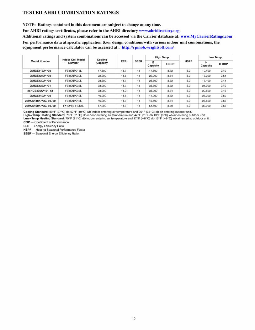
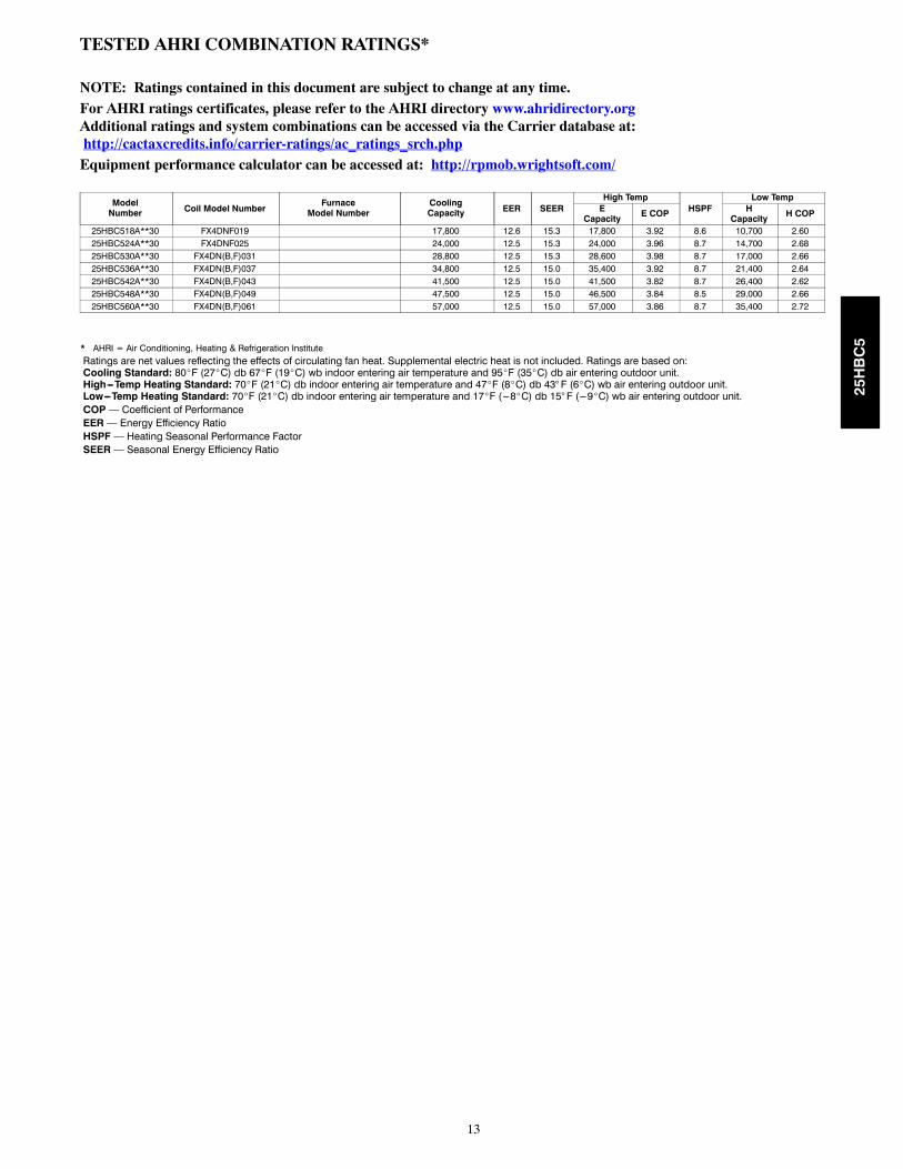
NOTE: Ratings contained in this document are subject to change at any time.For AHRI ratings certificates, please refer to the AHRI directory www.ahridirectory.orgAdditional ratings and system combinations can be accessed via the Carrier database at: www.MyCarrierRatings.com
For performance data at specific application &/or design conditions with various indoor unit combinations, theequipment performance calculator can be accessed at : http://rpmob.wrightsoft.com/
Cooling Standard: 80_F (27_C) db 67_F (19_C) wb indoor entering air temperature and 95_F (35_C) db air entering outdoor unit.High---Temp Heating Standard: 70_F (21_C) db indoor entering air temperature and 47_F (8_C) db 43° F (6_C) wb air entering outdoor unit.Low---Temp Heating Standard: 70_F (21_C) db indoor entering air temperature and 17_F (---8_C) db 15° F (---9_C) wb air entering outdoor unit.COP— Coefficient of PerformanceEER— Energy Efficiency RatioHSPF— Heating Seasonal Performance FactorSEER— Seasonal Energy Efficiency Ratio
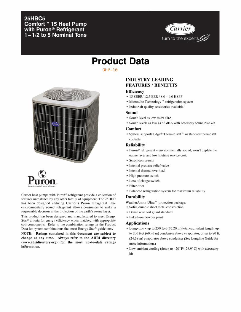
Product Data
25HBC5Comfort™ 15 Heat Pumpwith Puronr Refrigerant1---1/2 to 5 Nominal Tons
the environmentally sound refrigerant
Carrier heat pumps with Puronr refrigerant provide a collection offeatures unmatched by any other family of equipment. The 25HBChas been designed utilizing Carrier’s Puron refrigerant. Theenvironmentally sound refrigerant allows consumers to make aresponsible decision in the protection of the earth’s ozone layer.
This product has been designed and manufactured to meet EnergyStarr criteria for energy efficiency when matched with appropriatecoil components. Refer to the combination ratings in the ProductData for system combinations that meet Energy Starr guidelines.
NOTE: Ratings contained in this document are subject tochange at any time. Always refer to the AHRI directory(www.ahridirectory.org) for the most up--to--date ratingsinformation.
S Sound levels as low as 68 dBA with accessory sound blanket
ComfortS System supports Edger Thermidistatt or standard thermostat
controls
ReliabilityS Puronr refrigerant -- environmentally sound, won’t deplete the
ozone layer and low lifetime service cost.
S Scroll compressor
S Internal pressure relief valve
S Internal thermal overload
S High pressure switch
S Loss of charge switch
S Filter drier
S Balanced refrigeration system for maximum reliability
DurabilityWeatherArmor Ultrat protection package:S Solid, durable sheet metal construction
S Dense wire coil guard standard
S Baked--on powder paint
ApplicationsS Long--line -- up to 250 feet (76.20 m) total equivalent length, up
to 200 feet (60.96 m) condenser above evaporator, or up to 80 ft.
(24.38 m) evaporator above condenser (See Longline Guide for
more information.)
S Low ambient cooling (down to --20_F/--28.9_C) with accessory
kit
takako.baker
OHP-10
2
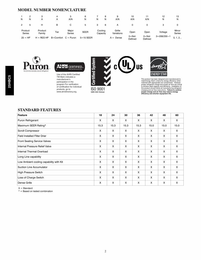
MODEL NUMBER NOMENCLATURE
1 2 3 4 5 6 7 8 9 10 11 12 13N N A A A/N N N N A/N A/N A/N N N
2 5 H B C 5 3 6 A 0 0 3 0
ProductSeries
ProductFamily Tier
MajorSeries SEER
CoolingCapacity
GrilleVariations Open Open Voltage
MinorSeries
25 = HP H = RES HP B=Comfort C = Puron 5=15 SEER A = Dense0=NotDefined
0=NotDefined
3=208/230---10, 1, 2...
the environmentally sound refrigerant
This product has been designed and manufactured tomeet Energy Star® criteria for energy efficiency whenmatched with appropriate coil components. However,proper refrigerant charge and proper air flow are criticalto achieve rated capacity and efficiency. Installation ofthis product should follow all manufacturing refrigerantcharging and air flow instructions. Failure to confirmproper charge and air flow may reduce energyefficiency and shorten equipment life.
Use of the AHRI CertifiedTM Mark indicates amanufacturer’s participation in the program For verification of certification for individual products, go to www.ahridirectory.org.
STANDARD FEATURESFeature 18 24 30 36 42 48 60
Puron Refrigerant X X X X X X X
Maximum SEER Rating* 15.3 15.3 15.3 15.3 15.0 15.0 15.0
Scroll Compressor X X X X X X X
Field Installed Filter Drier X X X X X X X
Front Seating Service Valves X X X X X X X
Internal Pressure Relief Valve X X X X X X X
Internal Thermal Overload X X X X X X X
Long Line capability X X X X X X X
Low Ambient cooling capability with Kit X X X X X X X
*Units are rated with 25 ft (7.6 m) of lineset length. See Vapor Line Sizing and Cooling Capacity Loss table when using other sizes and lengths of lineset.Note: See unit Installation Instruction for proper installation.
VAPOR LINE SIZING AND COOLING CAPACITY LOSSAcceptable vapor line diameters provide adequate oil return to the compressor while avoiding excessive capacity loss. The suction linediameters shown in the chart below are acceptable for HP systems with Puron refrigerant:
Vapor Line Sizing and Cooling Capacity Losses -- Puronr Refrigerant 1-- Stage Heat Pump Applications
UnitNominal
Size (Btuh)
MaximumLiquid LineDiameters(In. OD)
Vapor LineDiameters(In.) OD
Cooling Capacity Loss (%)Total Equivalent Line Length ft. (m)
StandardApplication Long Line Application Requires Accessories
26---50(7.9---15.2)
51---80(15.5---24.4)
81---100(24.7---30.5)
101---125(30.8---38.1)
126---150(38.4---45.7)
151---175(46.0---50.3)
176---200(53.6---60.0)
201---225(61.3---68.6)
226---250(68.9---76.2)
18,0001---StageHP withPuron
3/81/2 1 2 3 4 6 7 8 9 10
5/8 0 0 1 1 1 2 2 3 3
24,0001---StageHP withPuron
3/85/8 0 1 1 2 3 3 4 4 5
3/4 0 0 0 0 1 1 1 1 1
30,0001---StageHP withPuron
3/8
5/8 1 2 3 3 4 5 6 7 8
3/4 0 0 1 1 1 2 2 2 3
7/8 0 0 0 0 1 1 1 1 1
36,0001---StageHP withPuron
3/8
5/8 1 2 4 5 6 7 9 10 11
3/4 0 0 1 1 2 2 3 3 4
7/8 0 0 0 0 1 1 1 1 2
42,0001---StageHP withPuron
3/83/4 0 1 2 2 3 4 4 5 6
7/8 0 0 1 1 1 2 2 2 3
48,0001---StageHP withPuron
3/83/4 0 1 2 3 4 5 5 6 7
7/8 0 0 1 1 2 2 2 3 3
60,0001---StageHP withPuron
3/8
3/4 1 2 4 5 6 7 9 10 11
7/8 0 1 2 2 3 4 4 5 5
1---1/8 0 0 0 1 1 1 1 1 1
Standard Length = 80 ft. (24.4 m) or less total equivalent lengthApplications in this area are long line. Accessories are required as shown recommended on Long Line Application GuidelinesApplications in this area may have height restrictions that limit allowable total equivalent length, when outdoor unit is below indoor unit See Long Line Applica-tion Guidelines
25HBC5
takako.baker
8
ELECTRICAL DATA
UNIT SIZE V/PHOPER VOLTS* COMPR FAN
MCA
MIN WIRESIZE†
MAX LENGTHft (m))‡
MAXFUSE**or BRKAMPSMAX MIN LRA RLA FLA 60° C 75° C 60° C 75° C
* Permissible limits of the voltage range at which the unit will operate satisfactorily{ If wire is applied at ambient greater than 30_C, consult table 310---16 of the NEC (NFPA 70). The ampacity of non---metallic---sheathed cable (NM),
trade name ROMEX, shall be that of 60_C conditions, per the NEC (NFPA 70) Article 336---26. If other than uncoated (no---plated), 60 or 75_Cinsulation, copper wire (solid wire for 10 AWG or smaller, stranded wire for larger than 10 AWG) is used, consult applicable tables of the NEC (NFPA70).
} Length shown is as measured 1 way along wire path between unit and service panel for voltage drop not to exceed 2%.** Time---Delay fuse.FLA --- Full Load AmpsLRA --- Locked Rotor AmpsMCA --- Minimum Circuit AmpsRLA --- Rated Load AmpsNOTE: Control circuit is 24---V on all units and requires external power source. Copper wire must be used from service disconnect to unit.All motors/compressors contain internal overload protection.Complies with 2007 requirements of ASHRAE Standards 90.1
A--WEIGHTED SOUND POWER (dBA)
UNIT SIZESTANDARD
RATINGdBA
TYPICAL OCTAVE BAND SPECTRUM (dBA, without tone adjustment)
NOTE: Ratings contained in this document are subject to change at any time.For AHRI ratings certificates, please refer to the AHRI directory www.ahridirectory.orgAdditional ratings and system combinations can be accessed via the Carrier database at:http://cactaxcredits.info/carrier-ratings/ac_ratings_srch.phpEquipment performance calculator can be accessed at: http://rpmob.wrightsoft.com/
* AHRI = Air Conditioning, Heating & Refrigeration InstituteRatings are net values reflecting the effects of circulating fan heat. Supplemental electric heat is not included. Ratings are based on:Cooling Standard: 80_F (27_C) db 67_F (19_C) wb indoor entering air temperature and 95_F (35_C) db air entering outdoor unit.High---Temp Heating Standard: 70_F (21_C) db indoor entering air temperature and 47_F (8_C) db 43° F (6_C) wb air entering outdoor unit.Low---Temp Heating Standard: 70_F (21_C) db indoor entering air temperature and 17_F (---8_C) db 15° F (---9_C) wb air entering outdoor unit.COP— Coefficient of PerformanceEER— Energy Efficiency RatioHSPF— Heating Seasonal Performance FactorSEER— Seasonal Energy Efficiency Ratio


![Inversiones Fuber, S.A · SCS co.. LTD. Certificate of Conformity CTC Co Certificate of Conformity RoHS Certification Of Conformity ... 12.3 7.91 co-C180 C90-C270 +1-180 Diameter[m]](https://static.documents.pub/doc/80x56/6009434ea69050205b274844/inversiones-fuber-sa-scs-co-ltd-certificate-of-conformity-ctc-co-certificate.jpg)


