www.Fisher.com Fisher ™ 657 Diaphragm Actuators Size 80 and 100 Contents Introduction 1 ................................. Scope of Manual 1 ............................. Description 2 ................................. Specifications 3 ............................... Installation 3 .................................. Actuator Mounting 3 .......................... Loading Connection 4 ...................... Adjustments 4 ................................. Travel 4 ...................................... Spring 5 ..................................... Size 80 5 ................................. Size 100 5 ................................ Maintenance 7 ................................. Actuator 7 ................................... Size 80 Disassembly 7 ...................... Size 80 Assembly 8 ......................... Size 100 Disassembly 10 .................... Size 100 Assembly 11 ...................... Size 80 Side‐Mounted Handwheel 12 ............. Disassembly 12 ............................ Assembly 13 .............................. Size 80 Hydraulic Snubber 13 .................... Size 80 Top‐Mounted Handwheel (Adjustable Up Travel Stop) 13 ................ Disassembly 14 ............................ Assembly 14 .............................. Size 100 Top‐Mounted Handwheel (Adjustable Up Travel Stop) 14 ................ Disassembly 15 ............................ Figure 1. Sectional view of Fisher 657 Size 100 Actuator W0366‐1 Assembly 15 .............................. Parts Ordering 16 ............................... Parts List 16 ................................... Introduction Scope of Manual This instruction manual provides information on installation, adjustment, maintenance, and parts ordering for the Fisher 657 actuator in sizes 80 and 100. Refer to separate instruction manuals for information about other equipment and accessories used with these actuators. Do not install, operate, or maintain 657 actuators without being fully trained and qualified in valve, actuator, and accessory installation, operation, and maintenance. To avoid personal injury or property damage, it is important to carefully read, understand, and follow all the contents of this manual, including all safety cautions and warnings. If you have any questions about these instructions, contact your Emerson sales office or Local Business Partner before proceeding. Instruction Manual D100307X012 657 Size 80 and 100 Actuators June 2017
Scope of ManualThis instruction manual provides information on installation, adjustment, maintenance, and parts ordering for theFisher 657 actuator in sizes 80 and 100. Refer to separate instruction manuals for information about other equipmentand accessories used with these actuators.
Do not install, operate, or maintain 657 actuators without being fully trained and qualified in valve, actuator, andaccessory installation, operation, and maintenance. To avoid personal injury or property damage, it is important tocarefully read, understand, and follow all the contents of this manual, including all safety cautions and warnings. If youhave any questions about these instructions, contact your Emerson sales office or Local Business Partner beforeproceeding.
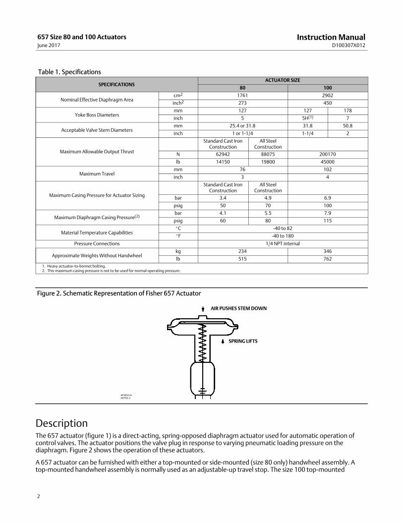
Acceptable Valve Stem Diametersmm 25.4 or 31.8 31.8 50.8
inch 1 or 1‐1/4 1‐1/4 2
Maximum Allowable Output Thrust
Standard Cast IronConstruction
All SteelConstruction
N 62942 88075 200170
lb 14150 19800 45000
Maximum Travelmm 76 102
inch 3 4
Maximum Casing Pressure for Actuator Sizing
Standard Cast IronConstruction
All SteelConstruction
bar 3.4 4.9 6.9
psig 50 70 100
Maximum Diaphragm Casing Pressure(2)bar 4.1 5.5 7.9
psig 60 80 115
Material Temperature Capabilities�C -40 to 82
�F -40 to 180
Pressure Connections 1/4 NPT internal
Approximate Weights Without Handwheelkg 234 346
lb 515 762
1. Heavy actuator‐to‐bonnet bolting.2. This maximum casing pressure is not to be used for normal operating pressure.
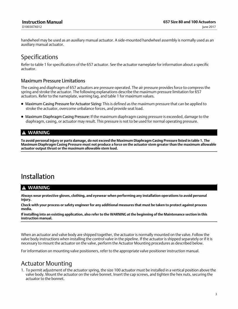
Figure 2. Schematic Representation of Fisher 657 Actuator
SPRING LIFTS
AIR PUSHES STEM DOWN
AF3833‐AA0792‐2
DescriptionThe 657 actuator (figure 1) is a direct‐acting, spring‐opposed diaphragm actuator used for automatic operation ofcontrol valves. The actuator positions the valve plug in response to varying pneumatic loading pressure on thediaphragm. Figure 2 shows the operation of these actuators.
A 657 actuator can be furnished with either a top‐mounted or side‐mounted (size 80 only) handwheel assembly. Atop‐mounted handwheel assembly is normally used as an adjustable‐up travel stop. The size 100 top‐mounted
Instruction ManualD100307X012
657 Size 80 and 100 ActuatorsJune 2017
3
handwheel may be used as an auxiliary manual actuator. A side‐mounted handwheel assembly is normally used as anauxiliary manual actuator.
SpecificationsRefer to table 1 for specifications of the 657 actuator. See the actuator nameplate for information about a specificactuator.
Maximum Pressure Limitations
The casing and diaphragm of 657 actuators are pressure operated. The air pressure provides force to compress thespring and stroke the actuator. The following explanations describe the maximum pressure limitation for 657actuators. Refer to the nameplate, warning tag, and table 1 for maximum values.
� Maximum Casing Pressure for Actuator Sizing: This is defined as the maximum pressure that can be applied tostroke the actuator, overcome unbalance forces, and provide seat load.
� Maximum Diaphragm Casing Pressure: If the maximum diaphragm casing pressure is exceeded, damage to thediaphragm, casing, or actuator may result. This pressure is not to be used for normal operating pressure.
WARNING
To avoid personal injury or parts damage, do not exceed the Maximum Diaphragm Casing Pressure listed in table 1. TheMaximum Diaphragm Casing Pressure must not produce a force on the actuator stem greater than the maximum allowableactuator output thrust or the maximum allowable stem load.
Installation
WARNING
Always wear protective gloves, clothing, and eyewear when performing any installation operations to avoid personalinjury.
Check with your process or safety engineer for any additional measures that must be taken to protect against processmedia.
If installing into an existing application, also refer to the WARNING at the beginning of the Maintenance section in thisinstruction manual.
When an actuator and valve body are shipped together, the actuator is normally mounted on the valve. Follow thevalve body instructions when installing the control valve in the pipeline. If the actuator is shipped separately or if it isnecessary to mount the actuator on the valve, perform the Actuator Mounting procedures as described below.
For information on mounting valve positioners, refer to the appropriate valve positioner instruction manual.
Actuator Mounting1. To permit adjustment of the actuator spring, the size 100 actuator must be installed in a vertical position above the
valve body. Mount the actuator on the valve bonnet. Insert the cap screws, and tighten the hex nuts, securing theactuator to the bonnet.
Instruction ManualD100307X012
657 Size 80 and 100 ActuatorsJune 2017
4
2. Screw valve stem locknuts (key 16, figure 4) all the way onto valve stem thread.
3. Connect an air supply to the diaphragm casing.
4. For push‐down‐to‐close valves, be sure the valve plug is on its seat. Apply pressure to ensure that the actuator stemis fully extended. Reduce actuator loading pressure to retract the stem approximately 3.2 mm (1/8‐inch).
5. For push‐down‐to‐open valves, move valve plug to closed position. On large body sizes, this may require the use ofa pry bar inserted through the body line opening. If the body is installed in a pipeline, the bottom flange (if one isused) can be removed and the valve plug pushed to the seat from the bottom opening. Pressure the actuator tomove the stem out 3.2 mm (1/8‐inch).
WARNING
To avoid personal injury due to the sudden uncontrolled movement of parts, do not loosen the stem connector cap screwswhen the stem connector has spring or loading pressure force applied to it.
CAUTION
Incomplete engagement of both valve stem and actuator stem in the stem connector can result in stripped threads orimproper operation. Be sure that the length of each stem clamped in the stem connector is equal to or greater than thediameter of that stem.
6. Clamp the actuator and valve plug stems between the two stem connector halves (key 26, figure 4). Insert andtighten the stem connector cap screws.
7. Thread the stem locknuts against the stem connector.
8. Align the travel indicator scale (key 18, figures 4 and 5) to show valve position.
Loading Connection1. Connect the loading pressure piping to the connection in the top of the diaphragm casing.
2. Remove the 1/4‐inch bushing (key 33, figure 4 and key 120, figure 5) to increase connection size, if necessary. Theconnection can be made with either piping or tubing.
3. Keep the length of tubing or piping as short as possible to avoid transmission lag in the control signal. If anaccessory (such as a volume booster or valve positioner) is used, be sure that the accessory is properly connected tothe actuator. Refer to the positioner instruction manual as necessary.
4. Cycle the actuator several times to check that the valve stem travel is correct and that the travel occurs when thecorrect pressure range is applied to the diaphragm.
5. If valve stem travel is incorrect, refer to the Travel procedure in the Adjustments section.
6. If the pressure range is incorrect, refer to the Spring procedure in the Adjustments section.
Adjustments
TravelMake travel adjustments when the motion observed during actuator travel is different from the travel stamped on theactuator nameplate. If the Actuator Mounting procedure was followed correctly, this adjustment should not benecessary.
Instruction ManualD100307X012
657 Size 80 and 100 ActuatorsJune 2017
5
When adjusting travel of a reverse‐acting (push‐down‐to‐open) valve, apply a slight pressure on the actuatordiaphragm. This moves the valve plug off the seat, reducing the chance of damaging the valve plug or seat duringadjustments.
1. Back the stem locknuts away from the stem connector, and slightly loosen the stem connector cap screws.
CAUTION
Do not use wrenches or other tools directly on the valve stem. Damage to the stem surface and subsequent damage to thevalve packing may result.
2. Tighten the locknuts together, using a wrench, then screw the valve stem either into the stem connector tolengthen travel or out of the stem connector to shorten travel.
3. Cycle the actuator to check the travel. If actual travel is not equal to the specified travel, adjust and check traveluntil correct. Tighten the stem connector cap screws when correct travel is obtained.
4. Raise the travel indicator disk by threading the stem locknuts against the stem connector.
SpringMake spring adjustments when the loading pressure range applied to achieve specified travel is not equal to thepressure range stamped on the actuator nameplate. Refer to the Bench Set pressure range on the nameplate when thevalve contains no pressure and the packing is loosely inserted in the bonnet. Refer to the Max. Allow. Supply on thenameplate when the valve is controlling the specified pressure drop and the packing is tightened to stop leaks aroundthe stem.
Monitor loading pressure carefully when making adjustments. Do not exceed the pressure specifications of either theloading regulator or the actuator casings.
Each actuator spring has a fixed pressure span. Changing the spring compression shifts the span up or down to makevalve travel coincide with the loading pressure range.
Size 80
Remove cover band (key 60, figure 4), insert a rod of approximately 12.7 mm (1/2‐inch) diameter into a hole in theadjusting screw (key 12, figure 4), and rotate the adjusting screw with the rod. Rotating the screw from left to right willincrease the loading pressure required to start actuator stem travel; opposite rotation will decrease the pressurerequired to start travel.
Size 100
CAUTION
The actuator must be in the vertical position when adjusting spring to avoid damage to thrust bearing (key 35, figure 5)and to properly position spacers required for adjustment.
Remove the shroud plate (key 107, figure 5), and loosen the jam nut (key 115, figure 5).
Instruction ManualD100307X012
657 Size 80 and 100 ActuatorsJune 2017
6
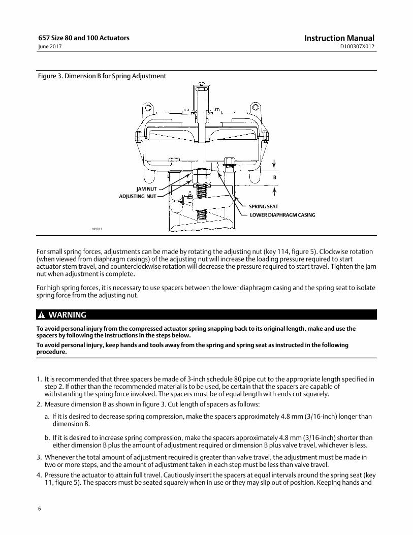
Figure 3. Dimension B for Spring Adjustment
LOWER DIAPHRAGM CASING
SPRING SEAT
JAM NUT
ADJUSTING NUT
A0950‐1
B
For small spring forces, adjustments can be made by rotating the adjusting nut (key 114, figure 5). Clockwise rotation(when viewed from diaphragm casings) of the adjusting nut will increase the loading pressure required to startactuator stem travel, and counterclockwise rotation will decrease the pressure required to start travel. Tighten the jamnut when adjustment is complete.
For high spring forces, it is necessary to use spacers between the lower diaphragm casing and the spring seat to isolatespring force from the adjusting nut.
WARNING
To avoid personal injury from the compressed actuator spring snapping back to its original length, make and use thespacers by following the instructions in the steps below.
To avoid personal injury, keep hands and tools away from the spring and spring seat as instructed in the followingprocedure.
1. It is recommended that three spacers be made of 3‐inch schedule 80 pipe cut to the appropriate length specified instep 2. If other than the recommended material is to be used, be certain that the spacers are capable ofwithstanding the spring force involved. The spacers must be of equal length with ends cut squarely.
2. Measure dimension B as shown in figure 3. Cut length of spacers as follows:
a. If it is desired to decrease spring compression, make the spacers approximately 4.8 mm (3/16‐inch) longer thandimension B.
b. If it is desired to increase spring compression, make the spacers approximately 4.8 mm (3/16‐inch) shorter thaneither dimension B plus the amount of adjustment required or dimension B plus valve travel, whichever is less.
3. Whenever the total amount of adjustment required is greater than valve travel, the adjustment must be made intwo or more steps, and the amount of adjustment taken in each step must be less than valve travel.
4. Pressure the actuator to attain full travel. Cautiously insert the spacers at equal intervals around the spring seat (key11, figure 5). The spacers must be seated squarely when in use or they may slip out of position. Keeping hands and
Instruction ManualD100307X012
657 Size 80 and 100 ActuatorsJune 2017
7
tools away from the spring and spring seat, slowly decrease loading pressure until the spring force holds the spacersfirmly between the spring seat and lower diaphragm casing (key 5, figure 5).
5. Loosen the jam nut. The adjusting nut can now be rotated clockwise (when viewed from the diaphragm casings) toincrease the loading pressure required to start actuator stem travel or counterclockwise to decrease the pressurerequired to start travel.
6. Pressure the actuator to move the spring seat away from the spacers, and carefully remove the spacers.
7. If the total adjustment required was greater than valve travel, repeat the procedure. It will be necessary to makenew spacers using the new dimension B and the remaining adjustment required or valve travel, whichever is less.Tighten the jam nut when adjustment is complete.
Maintenance
WARNING
Avoid personal injury or property damage from sudden release of process pressure or bursting of parts. Before performingany maintenance operations:
� Do not remove the actuator from the valve while the valve is still pressurized.
� Always wear protective gloves, clothing, and eyewear when performing any maintenance operations to avoid personalinjury.
� Disconnect any operating lines providing air pressure, electric power, or a control signal to the actuator. Be sure theactuator cannot suddenly open or close the valve.
� Use bypass valves or completely shut off the process to isolate the valve from process pressure. Relieve process pressurefrom both sides of the valve. Drain the process media from both sides of the valve.
� Vent the power actuator loading pressure and relieve any actuator spring precompression.
� Use lock‐out procedures to be sure that the above measures stay in effect while you work on the equipment.
� The valve packing box may contain process fluids that are pressurized, even when the valve has been removed from thepipeline. Process fluids may spray out under pressure when removing the packing hardware or packing rings, or whenloosening the packing box pipe plug.
� Check with your process or safety engineer for any additional measures that must be taken to protect against processmedia.
The maintenance instructions are divided into four sections: actuator (sizes 80 and 100); side‐mounted handwheelassembly (manual operator); hydraulic snubber; and top‐mounted handwheel assembly (adjustable‐up travel stop).
ActuatorThis procedure describes how the actuator can be completely disassembled and assembled. When inspection orrepairs are required, disassemble only those parts necessary to accomplish the job; then, start the assembly at theappropriate step.
Key numbers refer to figure 4 for size 80 actuators and figure 5 for size 100 actuators.
Size 80 Disassembly1. Bypass the control valve. Reduce the loading pressure to atmospheric, and remove the tubing or piping from the
top of the diaphragm casing (key 1).
Instruction ManualD100307X012
657 Size 80 and 100 ActuatorsJune 2017
8
WARNING
To avoid personal injury from the precompressed spring force thrusting the upper diaphragm casing (key 1) away from theactuator, relieve spring compression (step 2, below), and carefully remove casing cap screws (key 22) (step 4, below).
2. Remove cover band (key 60). Insert a rod of approximately 12.7 mm (1/2‐inch) diameter into a hole in the adjustingscrew (key 12), and rotate the adjusting screw from right to left until spring compression is relieved. If the actuatorhas a handwheel, rotate it counterclockwise, relieving all spring compression.
3. If necessary, the entire actuator may be removed from the valve body by unscrewing two cap screws from stemconnector (key 26) and removing actuator‐to‐bonnet bolting.
4. Unscrew diaphragm casing cap screws and nuts (keys 22 and 23), and lift off upper diaphragm casing (key 1).
5. Remove the molded diaphragm (key 2).
6. For actuators without snubber, remove diaphragm plate and stem (keys 4 and 10) as an assembly. This assemblycan be broken down further, if necessary, by removing the cap screw (key 3).
7. For actuators with snubber (see figure 7), unscrew cap screw (key 3), and remove diaphragm plate (key 4). Removestem connector (key 26). Unscrew cap screws (key 85), and remove cylinder assembly (key 74) and attached stemand upper seat (keys 10 and 90) from actuator.
To disassemble snubber:
a. Unscrew stem from piston/piston rod assembly (key 27).
b. Remove retaining rings, cylinder heads, and piston/piston rod assembly (keys 76, 75, and 27). Replace packingand O‐rings (keys 103, 104, 77 and 105) as required.
8. Remove actuator spring, upper sleeve, and spring seat (keys 6, 34 and 11).
9. Unscrew cap screws and nuts (keys 62 and 63), and remove spring case (key 29). Cap screws (key 62) on units withside‐mounted handwheel do not use hex nuts (key 63).
10. For actuators without side‐mounted handwheel, remove adjusting flange (key 36) and attached thrust bearingand adjusting screw (keys 35 and 12).
11. For actuators with side‐mounted handwheel (see figure 7), unscrew cap screws (key 64), and remove adjustingflange (key 36) and attached thrust bearing and adjusting screw (keys 35 and 12). Do not lose the key (key 47).
Size 80 Assembly1. Coat the threads of the adjusting flange (key 36) with anti‐seize lubricant (key 244). Replace the adjusting flange,
adjusting screw, and thrust bearing (keys 36, 12, and 35). Pack bearing with lithium grease lubricant (key 241).
For actuators with side‐mounted handwheel, install the key (key 47) on the adjusting flange (key 36). Coat theadjusting flange threads with anti‐seize lubricant. Install the adjusting flange so that the key engages the slot in thelower sleeve. Secure adjusting flange with cap screws (key 64). Adjust set screws (key 40, figure 7) to eliminate freeplay in handwheel bearings.
Note
Over‐tightening the set screws will make handwheel operation difficult.
2. Mount the spring case (key 29) to the yoke (key 9) using cap screws and hex nuts (keys 62 and 63).
Instruction ManualD100307X012
657 Size 80 and 100 ActuatorsJune 2017
9
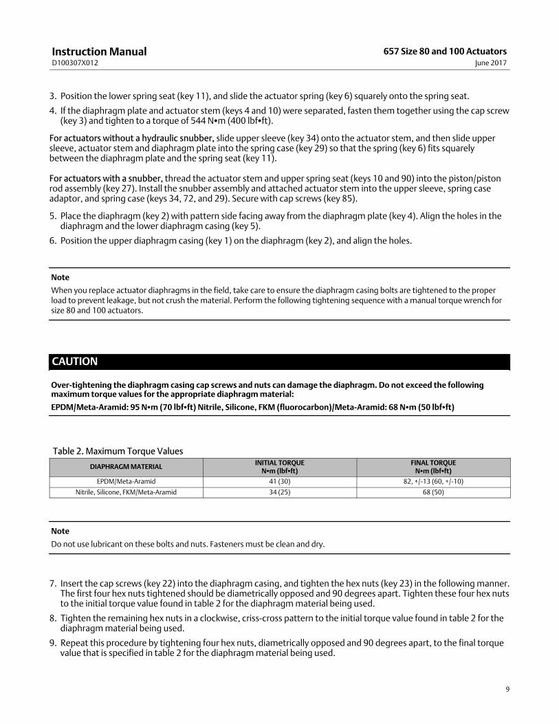
3. Position the lower spring seat (key 11), and slide the actuator spring (key 6) squarely onto the spring seat.
4. If the diaphragm plate and actuator stem (keys 4 and 10) were separated, fasten them together using the cap screw(key 3) and tighten to a torque of 544 N�m (400 lbf�ft).
For actuators without a hydraulic snubber, slide upper sleeve (key 34) onto the actuator stem, and then slide uppersleeve, actuator stem and diaphragm plate into the spring case (key 29) so that the spring (key 6) fits squarelybetween the diaphragm plate and the spring seat (key 11).
For actuators with a snubber, thread the actuator stem and upper spring seat (keys 10 and 90) into the piston/pistonrod assembly (key 27). Install the snubber assembly and attached actuator stem into the upper sleeve, spring caseadaptor, and spring case (keys 34, 72, and 29). Secure with cap screws (key 85).
5. Place the diaphragm (key 2) with pattern side facing away from the diaphragm plate (key 4). Align the holes in thediaphragm and the lower diaphragm casing (key 5).
6. Position the upper diaphragm casing (key 1) on the diaphragm (key 2), and align the holes.
Note
When you replace actuator diaphragms in the field, take care to ensure the diaphragm casing bolts are tightened to the properload to prevent leakage, but not crush the material. Perform the following tightening sequence with a manual torque wrench forsize 80 and 100 actuators.
CAUTION
Over‐tightening the diaphragm casing cap screws and nuts can damage the diaphragm. Do not exceed the followingmaximum torque values for the appropriate diaphragm material:
Do not use lubricant on these bolts and nuts. Fasteners must be clean and dry.
7. Insert the cap screws (key 22) into the diaphragm casing, and tighten the hex nuts (key 23) in the following manner.The first four hex nuts tightened should be diametrically opposed and 90 degrees apart. Tighten these four hex nutsto the initial torque value found in table 2 for the diaphragm material being used.
8. Tighten the remaining hex nuts in a clockwise, criss‐cross pattern to the initial torque value found in table 2 for thediaphragm material being used.
9. Repeat this procedure by tightening four hex nuts, diametrically opposed and 90 degrees apart, to the final torquevalue that is specified in table 2 for the diaphragm material being used.
Instruction ManualD100307X012
657 Size 80 and 100 ActuatorsJune 2017
10
10. Tighten the remaining hex nuts in a clockwise, criss‐cross pattern to the final torque value that is specified in table 2 for the diaphragm material being used.
11. After the last hex nut is tightened complete another tightening sequence, this time in a circular pattern aroundthe bolt circle to the final torque value that is specified in table 2 for the diaphragm material being used.
12. Once completed, no more tightening is recommended.
13. Mount the actuator on the valve in accordance with the procedures in the Installation section.
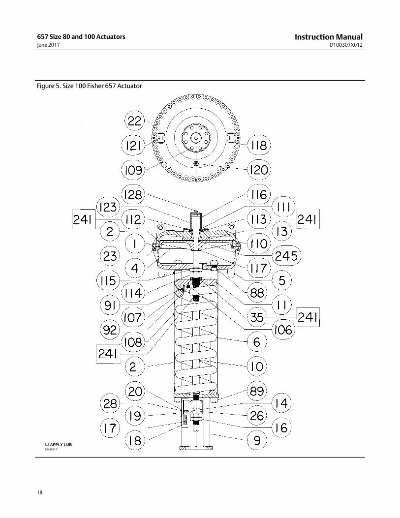
Size 100 Disassembly
Key numbers used in the following procedure are shown in figure 5 except when indicated.
Note
Two construction variations of the size 100 are based on spring length. Group 1 springs have a free length of 845 mm (33‐1/4inches), and group 2 springs have a free length of 419 mm (16‐1/2 inches).
WARNING
To avoid personal injury from the precompressed spring force thrusting the upper diaphragm casing (key 1) away from theactuator, relieve spring compression (step 1, below), and carefully remove casing cap screws (key 22) (step 7, below).
1. Remove shroud plate (key 107), loosen jam nut (key 115), and rotate adjusting nut (key 114) until springcompression is relieved.
Note
To relieve spring compression when high spring forces exist, refer to the Adjusting Actuator Spring section, and follow theinstructions given for size 100 actuators with high spring forces.
2. Remove the pressure tubing or piping from the top of the diaphragm casing.
3. For actuators with top‐mounted handwheel, rotate handwheel (key 51, figure 8) counterclockwise as far as it willgo, unscrew cap screws (key 109, figure 5), and remove handwheel and gear case assembly (key 65, figure 8).
4. For actuators without top‐mounted handwheel, unscrew cap screws (key 109), and remove diaphragm casingcover (key 123).
5. If necessary, remove the actuator from the valve body by separating the stem connector (key 26) and removing theactuator‐to‐bonnet bolting. Separate the stem connector by loosening the stem locknuts (key 16) and unscrewingthe four cap screws.
6. Unscrew and remove actuator stem extension (key 116).
7. Unscrew cap screws (key 22), and remove upper diaphragm casing (key 1).
8. Remove backup plate, diaphragm retainer, diaphragm, diaphragm plate, and washer (keys 13, 110, 2, 4, and 117).
9. Unscrew the nuts that attach lower diaphragm casing (key 5) to actuator tie rods (key 21).
10. Remove lower diaphragm casing from tie rods and remove hex jam nut, adjusting nut thrust bearing (used withgroup 1 springs only), and spring seat (keys 115, 114, 35, and 11).
Instruction ManualD100307X012
657 Size 80 and 100 ActuatorsJune 2017
11
11. Remove seal bushing (key 111) and diaphragm casing cover O‐rings (keys 112 and 113) from upper diaphragmcasing (key 123). Replace with new parts if necessary. Apply lithium grease lubricant to the O‐rings.
12. Remove actuator spring (key 6).
Size 100 Assembly
Note
Units using a group 2 spring require one spring seat (key 11) on each end of the spring (key 6); units using a group 1 spring requireonly one spring seat on the diaphragm end of the spring as shown in figure 5.
1. Place the spring and spring seats (keys 6 and 11) inside the spring case.
2. For actuators using a group 1 spring, pack the thrust bearing (key 35) with lithium grease lubricant (key 241). Placebearing on the spring seat.
3. Screw the hex jam nut and adjusting nut (keys 115 and 114) onto the actuator stem.
4. Install the lower diaphragm casing (key 5) on the actuator tie rods (key 21). Secure with hex nuts.
Note
Before installing diaphragm plate (key 4), rotate adjusting nut (key 114) until the top of the actuator stem is 264 mm (10‐3/8inches) above the inside surface of the lower casing (key 5).
When installing diaphragm (key 2), be certain that the rubber side of the diaphragm faces away from the spring.
CAUTION
To avoid product damage, smooth the edge of the diaphragm to avoid wrinkling, and be careful that the diaphragm folddoes not get pinched when the upper casing (key 1) is installed.
5. Install washer, diaphragm plate, diaphragm, diaphragm retainer, and backup plate (keys 117, 4, 2, 110 and 13).
6. Apply lithium grease lubricant (key 241) to the thread on the diaphragm end of the actuator stem (key 10).
7. Position the upper diaphragm casing (key 1) on the diaphragm (key 2), and align the holes.
Note
If backup plate (key 13) interferes with installation of upper casing, rotate adjusting nut (key 114) to move the plate.
Note
When you replace actuator diaphragms in the field, take care to ensure the diaphragm casing bolts are tightened to the properload to prevent leakage, but not crush the material. Perform the following tightening sequence with a manual torque wrench forsize 80 and 100 actuators.
Instruction ManualD100307X012
657 Size 80 and 100 ActuatorsJune 2017
12
CAUTION
Over‐tightening the diaphragm casing cap screws and nuts can damage the diaphragm. Do not exceed 68 N�m (50 lbf�ft)torque.
Note
Do not use lubricant on these bolts and nuts. Fasteners must be clean and dry.
8. Insert the cap screws (key 22), and tighten the hex nuts (key 23) in the following manner. The first four hex nutstightened should be diametrically opposed and 90 degrees apart. Tighten these four hex nuts to 34 N�m (25 lbf�ft).
9. Tighten the remaining hex nuts in a clockwise, criss‐cross pattern to 34 N�m (25 lbf�ft).
10. Repeat this procedure by tightening four hex nuts, diametrically opposed and 90 degrees apart, to a torque of 68N�m (50 lbf�ft).
11. Tighten the remaining hex nuts in a clockwise, criss‐cross pattern to 68 N�m (50 lbf�ft).
12. After the last hex nut is tightened to 68 N�m (50 lbf�ft), all of the hex nuts should be tightened again to 68 N�m(50 lbf�ft) in a circular pattern around the bolt circle.
13. Once completed, no more tightening is recommended.
14. Install the actuator stem extension (key 116), diaphragm casing cover O‐rings (keys 112 and 113), and sealbushing (key 111). Install the gear case cover (key 123) or the handwheel assembly (see figure 8).
15. Mount the actuator on the valve, and secure with the actuator‐to‐bonnet bolting. Refer to the Installation sectionto connect actuator stem to valve plug stem.
Size 80 Side‐Mounted HandwheelThe side‐mounted handwheel assembly (figure 7) is normally used as a manual operator. The handwheel can bemounted in either of two positions so that, regardless of valve plug action, counterclockwise rotation always opens thevalve. The assembly is a continuously connected type with an indicator to show neutral position. By rotatinghandwheel away from neutral, the handwheel can be used to limit travel in either direction but not both directions atthe same time.
A grease fitting is provided on the gear box for periodic gear lubrication with a general‐purpose grease.
Instructions are given below for complete disassembly and assembly. Perform the disassembly only as far as necessaryto accomplish the required maintenance; then, begin the assembly at the appropriate step.
Key numbers refer to figure 7.
Disassembly1. Complete steps 1 through 9 of the disassembly portion of the size 80 actuator section.
2. Unscrew cap screws (key 64), and remove adjusting flange (key 36). Do not lose the key (key 47).
3. Unscrew the two screws (key 28), and remove travel stop indicator (key 58) from lower sleeve (key 46).
4. Turn handwheel (key 51) to raise lower sleeve. Continue turning handwheel until lower sleeve is free of worm gear(key 44). Lift out lower sleeve, bearing and gear retainer, thrust bearings, and worm gear (keys 46, 66, 67, and 44).
5. The worm shaft (key 45) and associated parts can be removed in order to replace or lubricate them. First, removethe handwheel cap (key 54) and the handwheel (key 51). Do not lose the small ball or spring (keys 55 and 56).
Instruction ManualD100307X012
657 Size 80 and 100 ActuatorsJune 2017
13
6. Loosen the two set screws (key 41), and unscrew the two worm retainers (keys 48 and 49). The ball bearings (key50) will come out with the retainers. Remove the worm shaft (key 45).
Assembly1. Pack the ball bearings (key 50) with lithium grease lubricant, and insert one ball bearing in the back worm retainer
(key 49) as shown in figure 7 (section C‐C).
2. Thread the back worm retainer and ball bearing (keys 49 and 50) into the gear case. Align the slot in the wormretainer with the set screw hole in the gear case, insert the set screw (key 41), and tighten it.
3. Coat the worm shaft (key 45) threads with anti‐seize lubricant (key 244), and slide the shaft into the gear case sothat the end of the shaft fits snugly in the back worm retainer.
4. Insert the bearing in the front worm retainer (key 48), and thread the retainer and ball bearing into the gear case. Align the slot in the retainer with the set screwhole in the gear case, insert the set screw (key 41), and tighten it.
5. Put the spring and ball (keys 56 and 55) in the handwheel (key 51). Slide the handwheel onto the worm shaft (key45). Thread the handwheel cap (key 54) onto the worm shaft.
6. Pack the two thrust bearings (key 67) with lithium grease lubricant. Install one thrust bearing; then, install theworm gear (key 44) followed by the second thrust bearing and the bearing and gear retainer (key 66).
7. The lower sleeve (key 46) has two screw holes in one end. Coat the sleeve threads with lithium grease lubricant,slide the end of the lower sleeve with the holes into the thrust bearing (key 67), turn the handwheel, and feed thesleeve through the worm gear. Continue turning the handwheel until the lower sleeve protrudes from the gearcase. Fasten the travel stop indicator (key 58) to the sleeve with the two machine screws (key 28).
8. Install the key (key 47) on the adjusting flange (key 36). Coat the adjusting flange threads with anti‐seize lubricant(key 244). Install the adjusting flange so that the key engages the slot in the lower sleeve. Secure adjusting flangewith cap screws (key 64).
9. Adjust set screws (key 40) to eliminate free play in the bearings.
Note
Over‐tightening the set screws will make handwheel operation difficult.
10. Install the adjusting screw and thrust bearings (keys 12 and 35). Pack bearings with lithium grease lubricant (key241), and install as shown in figure 7.
11. Slide the spring case (key 29) into position, and secure with cap screws (key 62).
12. Complete steps 3 through 8 of the size 80 actuator assembly section.
Size 80 Hydraulic SnubberThe size 80 657 is available with a hydraulic snubber, as shown in figure 7, to dampen vertical instability of actuatorstem movement. The snubber is adjusted by rotating the adjusting screws (key 83, figure 7) counterclockwise out ofthe reservoir (key 79, figure 7) to increase damping action and clockwise to decrease damping action. The adjustingscrew on the right (the lower of the two adjusting screws in section B‐B of figure 7) regulates downward dampingaction, and the screw on the left regulates upward damping action.
Size 80 Top‐Mounted Handwheel (Adjustable Up Travel Stop)
CAUTION
If repeated or daily manual operation is expected, and the actuator is equipped with a casing‐mounted travel stop ortop‐mounted handwheel, the diaphragm could be subject to excessive wear.
Instruction ManualD100307X012
657 Size 80 and 100 ActuatorsJune 2017
14
The actuator should be equipped with a side‐mounted handwheel, which is designed for more frequent use as a manualoperator.
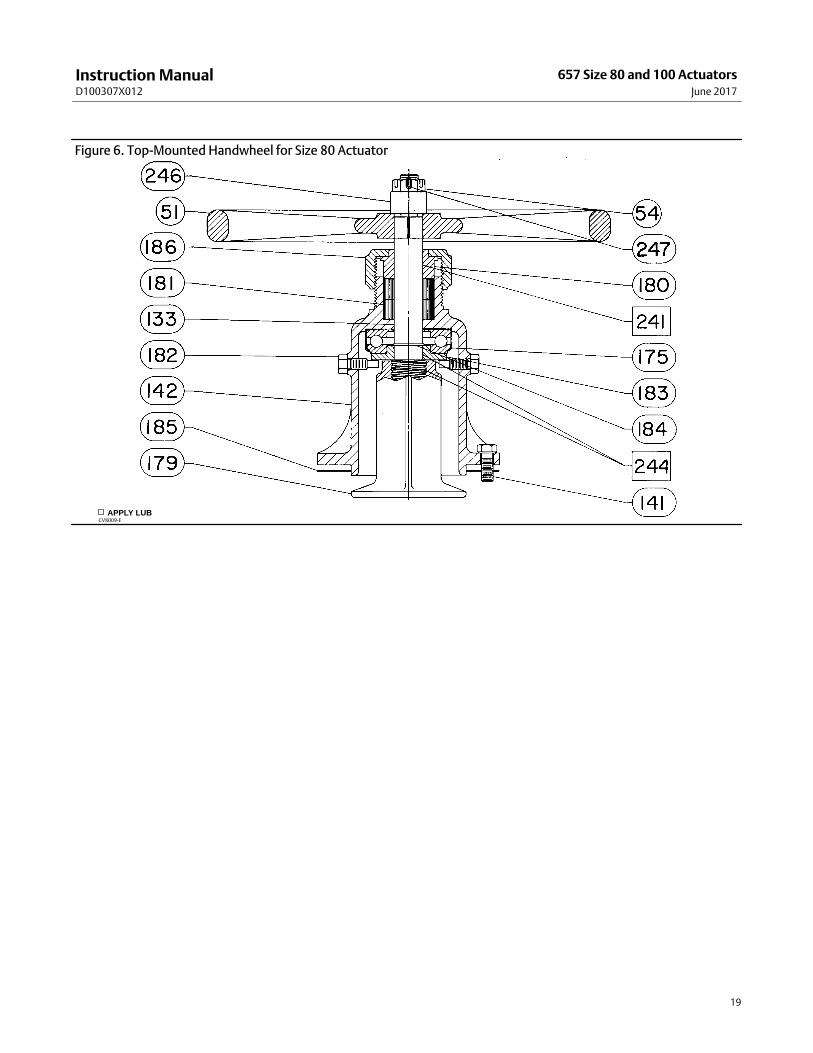
A top‐mounted handwheel assembly is normally used as an adjustable‐up travel stop to limit full retraction of theactuator stem. Turning the handwheel clockwise turns the handwheel stem (key 133, figure 6) into the diaphragmcasing and forces the pressure block assembly (key 179, figure 6) against the diaphragm and diaphragm plate.Instructions are given below for complete disassembly and assembly. Perform the disassembly only as far as necessaryto accomplish the required maintenance; then, begin the assembly at the appropriate step.
Key numbers refer to figure 4 for actuator parts and figure 6 for handwheel parts.
Disassembly1. Bypass the control valve. Reduce the loading pressure to atmospheric, and remove the tubing or piping from the
diaphragm casing (key 1).
WARNING
To avoid personal injury from the precompressed spring force thrusting the upper diaphragm casing (key 1) away from theactuator, relieve spring compression (step 2, below), and carefully remove casing cap screws (key 141) (step 3, below).
2. Remove cover band (key 60). Insert a rod of approximately 12.7 mm (1/2‐inch) diameter into a hole in the adjustingscrew (key 12), and rotate the adjusting screw from right to left until spring compression is relieved. Rotatehandwheel to be sure it is not compressing actuator spring.
3. Unscrew cap screws (key 141), and remove handwheel assembly.
4. Remove hex nut (key 54), and lift off the handwheel.
5. Unscrew support screws (key 182), and remove pressure block, stem, stem collar, and thrust bearing (keys 179,133, 183, and 175).
6. Unscrew body nut (key 186), and remove gland (key 180). If necessary, remove and replace packing rings (key 181).
Assembly1. Install new packing rings and gland (keys 181 and 180), and thread the body nut (key 186) onto the body.
2. Lubricate the thrust bearing and stem (keys 175 and 133), with lithium grease lubricant (key 241). Slide stem, stemcollar, thrust bearing, and pressure block (keys 133, 183, 175, and 179) into the body as shown in figure 6 andinstall support screws (key 182).
3. Install handwheel and hex nut (keys 51 and 54).
4. Install a new handwheel gasket (key 185).
5. Mount the handwheel assembly on the diaphragm casing, and secure with cap screws (key 141).
6. Reconnect pressure tubing or piping to actuator casing.
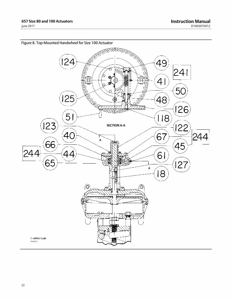
Size 100 Top‐Mounted Handwheel (Adjustable Up Travel Stop)A top‐mounted handwheel assembly is normally used as an adjustable‐up travel stop to limit full retraction of theactuator stem. Clockwise rotation of the handwheel (key 51) moves the actuator stem (key 10) downward,compressing the spring (key 6). Spring action returns the stem as the handwheel is turned counterclockwise.Instructions are given below for complete disassembly and assembly. Perform the disassembly only as far as necessaryto accomplish the required maintenance; then, begin the assembly at the appropriate step.
Instruction ManualD100307X012
657 Size 80 and 100 ActuatorsJune 2017
15
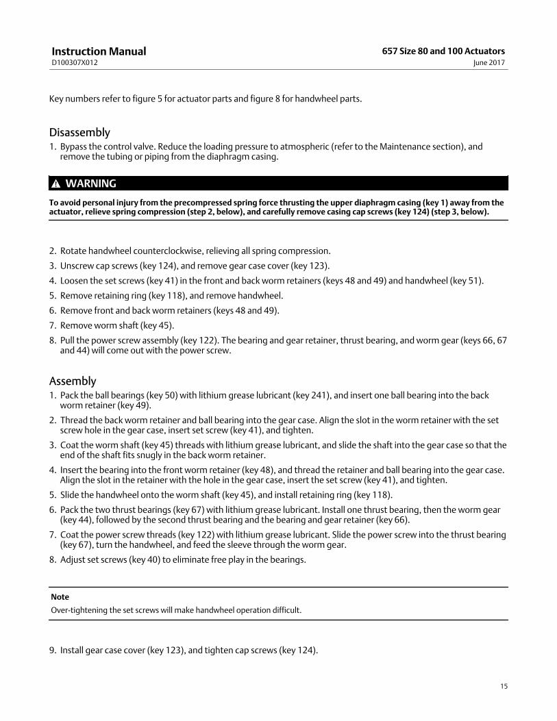
Key numbers refer to figure 5 for actuator parts and figure 8 for handwheel parts.
Disassembly1. Bypass the control valve. Reduce the loading pressure to atmospheric (refer to the Maintenance section), and
remove the tubing or piping from the diaphragm casing.
WARNING
To avoid personal injury from the precompressed spring force thrusting the upper diaphragm casing (key 1) away from theactuator, relieve spring compression (step 2, below), and carefully remove casing cap screws (key 124) (step 3, below).
2. Rotate handwheel counterclockwise, relieving all spring compression.
3. Unscrew cap screws (key 124), and remove gear case cover (key 123).
4. Loosen the set screws (key 41) in the front and back worm retainers (keys 48 and 49) and handwheel (key 51).
5. Remove retaining ring (key 118), and remove handwheel.
6. Remove front and back worm retainers (keys 48 and 49).
7. Remove worm shaft (key 45).
8. Pull the power screw assembly (key 122). The bearing and gear retainer, thrust bearing, and worm gear (keys 66, 67and 44) will come out with the power screw.
Assembly1. Pack the ball bearings (key 50) with lithium grease lubricant (key 241), and insert one ball bearing into the back
worm retainer (key 49).
2. Thread the back worm retainer and ball bearing into the gear case. Align the slot in the worm retainer with the setscrew hole in the gear case, insert set screw (key 41), and tighten.
3. Coat the worm shaft (key 45) threads with lithium grease lubricant, and slide the shaft into the gear case so that theend of the shaft fits snugly in the back worm retainer.
4. Insert the bearing into the front worm retainer (key 48), and thread the retainer and ball bearing into the gear case.Align the slot in the retainer with the hole in the gear case, insert the set screw (key 41), and tighten.
5. Slide the handwheel onto the worm shaft (key 45), and install retaining ring (key 118).
6. Pack the two thrust bearings (key 67) with lithium grease lubricant. Install one thrust bearing, then the worm gear(key 44), followed by the second thrust bearing and the bearing and gear retainer (key 66).
7. Coat the power screw threads (key 122) with lithium grease lubricant. Slide the power screw into the thrust bearing(key 67), turn the handwheel, and feed the sleeve through the worm gear.
8. Adjust set screws (key 40) to eliminate free play in the bearings.
Note
Over‐tightening the set screws will make handwheel operation difficult.
9. Install gear case cover (key 123), and tighten cap screws (key 124).
Instruction ManualD100307X012
657 Size 80 and 100 ActuatorsJune 2017
16
Parts OrderingEach actuator has a serial number stamped on the nameplate. Always refer to this number when corresponding withyour Emerson sales office or Local Business Partner regarding replacement parts or technical information.
WARNING
Use only genuine Fisher replacement parts. Components that are not supplied by Emerson Automation Solutions shouldnot, under any circumstances, be used in any Fisher valve, because they may void your warranty, might adversely affect theperformance of the valve, and could cause personal injury and property damage.
Parts List
Note
Contact your Emerson sales office or Local Business Partner for Part
Figure 6. Top‐Mounted Handwheel for Size 80 Actuator
APPLY LUBCV8009‐E
Instruction ManualD100307X012
657 Size 80 and 100 ActuatorsJune 2017
20
Size 80 Side‐Mtd Handwheel
Key Description
7 Travel Stop
17 Machine Screw
28 Machine Screw
40 Set Screw
41 Set Screw
44 Worm Gear
45 Worm Shaft
46 Lower Sleeve
47 Key
48 Front Worm Retainer
49 Back Worm Retainer
50 Ball Bearing
51 Handwheel
52 Handgrip
53 Handgrip Bolt
54 Handwheel Cap
55 Ball
56 Spring
58 Travel Indicator
61 Grease Fitting
64 Cap Screw
65 Gear Case
66 Bearing & Gear Retainer
67 Thrust Bearing
68 Cap Screw
69 Indicator Scale
70 Stop Indicator Bracket
71 Machine Screw
243 Pliable sealant (not furnished with actuator)
Size 80 Top‐Mtd Handwheel(Adjustable Up Travel Stop) 51 Handwheel
54 Nut
133 Stem
141 Cap Screw
142 Handwheel Body
175 Thrust Bearing
179 Pressure Block
180 Gland
181* Packing Ring, TFE‐graphite (2 req'd)
182 Support Screw
183 Stem Collar
184 Retaining Ring
185* Gasket, composition
186 Body Nut
241 Lithium grease (not furnished with actuator)
246 Spacer
247 Cotter Pin
Size 100 Top‐Mtd Handwheel(Adjustable Up Travel Stop)Key Description
17 Machine Screw
40 Set Screw
41 Set Screw
44 Worm Gear
45 Worm Shaft
48 Front Worm Retainer
49 Back Worm Retainer
50 Ball Bearing
51 Handwheel
61 Grease Fitting
65 Gear Case
66 Bearing & Gear Retainer
67 Thrust Bearing
118 Retaining Ring
122 Power Screw Ass'y
123 Gear Case Cover
124 Cap Screw
125 Hex Jam Nut
126 Woodruff Key
127 Slot Cover
Size 80 Hydraulic Snubber 27 Piston/Piston Rod Ass'y
63 Hex Nut
72 Spring Case Adaptor
73 Cap Screw
74 Cylinder
75 Cylinder Head
76 Retaining Ring
77* O‐Ring, nitrile (2 req'd)
78* Piston Ring, iron (2 req'd)
79 Reservoir
80* O‐Ring, nitrile
81 Cap Screw
82* O‐Ring, nitrile (2 req'd)
83 Valve Adj Screw
84 Jam Nut
85 Cap Screw
86 Pipe Plug
87 Pipe Plug
90 Upper Spring Seat
93 Hydraulic Fluid
94* O‐Ring, nitrile (2 req'd)
95 Orifice
96 Bypass & Check Valve Plug
97 Spring
98 E‐Ring
99 Bushing
100 Flange
101 Packing Sleeve
102 Machine Screw
103* Packing, nitrile (8 req'd)
104* Packing, CR (chloroprene) & cotton (4 req'd)
105* Packing Sleeve O‐Ring, nitrile (2 req'd)
*Recommended spare parts
Instruction ManualD100307X012
657 Size 80 and 100 ActuatorsJune 2017
21
Figure 7. Size 80 Fisher 657 Actuator with Side‐Mounted Handwheel and Hydraulic Snubber
APPLY LUB50A8774‐C
BB
VIEW A
CC
VIEW A
SECTION B‐B
SECTION C‐C
Instruction ManualD100307X012
657 Size 80 and 100 ActuatorsJune 2017
22
Figure 8. Top‐Mounted Handwheel for Size 100 Actuator
APPLY LUB50A2622‐F
A
A
SECTION A‐A
Instruction ManualD100307X012
657 Size 80 and 100 ActuatorsJune 2017
23
Instruction ManualD100307X012
657 Size 80 and 100 ActuatorsJune 2017
24
Emerson Automation Solutions Marshalltown, Iowa 50158 USASorocaba, 18087 BrazilCernay, 68700 FranceDubai, United Arab EmiratesSingapore 128461 Singapore
www.Fisher.com
The contents of this publication are presented for informational purposes only, and while every effort has been made to ensure their accuracy, they are notto be construed as warranties or guarantees, express or implied, regarding the products or services described herein or their use or applicability. All sales aregoverned by our terms and conditions, which are available upon request. We reserve the right to modify or improve the designs or specifications of suchproducts at any time without notice.
� 1973, 2017 Fisher Controls International LLC. All rights reserved.
Fisher is a mark owned by one of the companies in the Emerson Automation Solutions business division of Emerson Electric Co. Emerson AutomationSolutions, Emerson, and the Emerson logo are trademarks and service marks of Emerson Electric Co. All other marks are the property of their respectiveowners.
Neither Emerson, Emerson Automation Solutions, nor any of their affiliated entities assumes responsibility for the selection, use or maintenanceof any product. Responsibility for proper selection, use, and maintenance of any product remains solely with the purchaser and end user.