Scope of ManualThis instruction manual includes installation,maintenance, and parts information for the FisherGX control valve and actuator system.
Do not install, operate or maintain a GX valve andactuator system without first � being fully trained andqualified in valve, actuator and accessoryinstallation, operation and maintenance, and �carefully reading and understanding the contents ofthis manual. If you have any questions about theseinstructions contact your Emerson ProcessManagement sales office before proceeding.
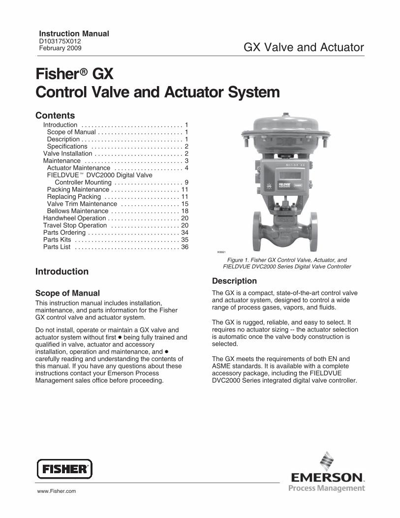
Figure 1. Fisher GX Control Valve, Actuator, andFIELDVUE DVC2000 Series Digital Valve Controller
W8861
DescriptionThe GX is a compact, state-of-the-art control valveand actuator system, designed to control a widerange of process gases, vapors, and fluids.
The GX is rugged, reliable, and easy to select. Itrequires no actuator sizing -- the actuator selectionis automatic once the valve body construction isselected.
The GX meets the requirements of both EN andASME standards. It is available with a completeaccessory package, including the FIELDVUEDVC2000 Series integrated digital valve controller.
Instruction ManualD103175X012February 2009 GX Valve and Actuator
GX Valve and ActuatorInstruction Manual
February 2009
2
Table 1. Fisher GX Valve Specifications
Specifications EN ASMEValve Body Size DN 15, 20, 25, 40, 50, 80, 100, 150 NPS 1/2, 3/4, 1, 1-1/2, 2, 3, 4, and 6
Pressure Rating PN 10 / 16 / 25 / 40 per EN 1092-1 CL150 / 300 per ASME B16.34
End Connections Flanged raised face per EN 1092-1 Flanged raised face per ASME B16.5
Face-to-Face Dimensions Consistent with EN 558-1 Series 1 Consistent with ANSI/ISA 75.08.01
Shutoff per IEC 60534-4 and ANSI/FCI 70-2
Metal seat - Class IV (standard)Metal seat - Class V (optional)
PTFE seat - Class VI (optional)(1)
Flow Direction Flow-up (Cavitrol� III cage, Flow down)
Flow Control Characteristics Equal Percentage and Linear
Trim Style
Port Diameters Trim Style Description4.8 mm Micro-Flow trim (unbalanced)
9.5, 14, 22 mmStem-Guided with Contoured Plug (unbalanced) or Port-Guided with Cavitrol III trim (unbalanced)
36, 46 mm Port-Guided Plug (unbalanced)
70, 90, 136 mmBalanced Trim with Contoured plug (standard) or Unbalanced Port-GuidedPlug (optional)
Handwheel Available as an option
Travel Stop Available as an option1. For 4.8 to 14 mm ports, Class VI shutoff is achieved without PTFE seat.
Valve Installation
WARNING
Always wear protective gloves,clothing, and eyewear whenperforming any installation operationsto avoid personal injury.
Personal injury or equipment damagecaused by sudden release of pressureor bursting of pressure retaining partsmight result if service conditionsexceed those for which the productwas intended. To avoid injury ordamage, provide a relief valve for overpressure protection as required bygovernment or accepted industrycodes and good engineering practices.
Check with your process or safetyengineer for any additional measuresthat must be taken to protect againstprocess media.
If installing into an existingapplication, also refer to the WARNINGat the beginning of the Maintenancesection in this instruction manual.
CAUTION
This valve is intended for a specificrange of pressures, temperatures andother application specifications.Applying different pressure andtemperatures to the valve could resultin parts damage, malfunction of thecontrol valve or loss of control of theprocess. Do not expose this product toservice conditions or variables otherthan those for which the product wasintended. If you are not sure whatthese conditions are you shouldcontact your Emerson ProcessManagement sales office for morecomplete specifications. Provide theproduct serial number (shown on thenameplate, figure 2) and all otherpertinent information.
WARNING
If you move or work on an actuatorinstalled on a valve with loadingpressure applied, keep your hands andtools away from the stem travel path to
GX Valve and ActuatorInstruction Manual
February 2009
3
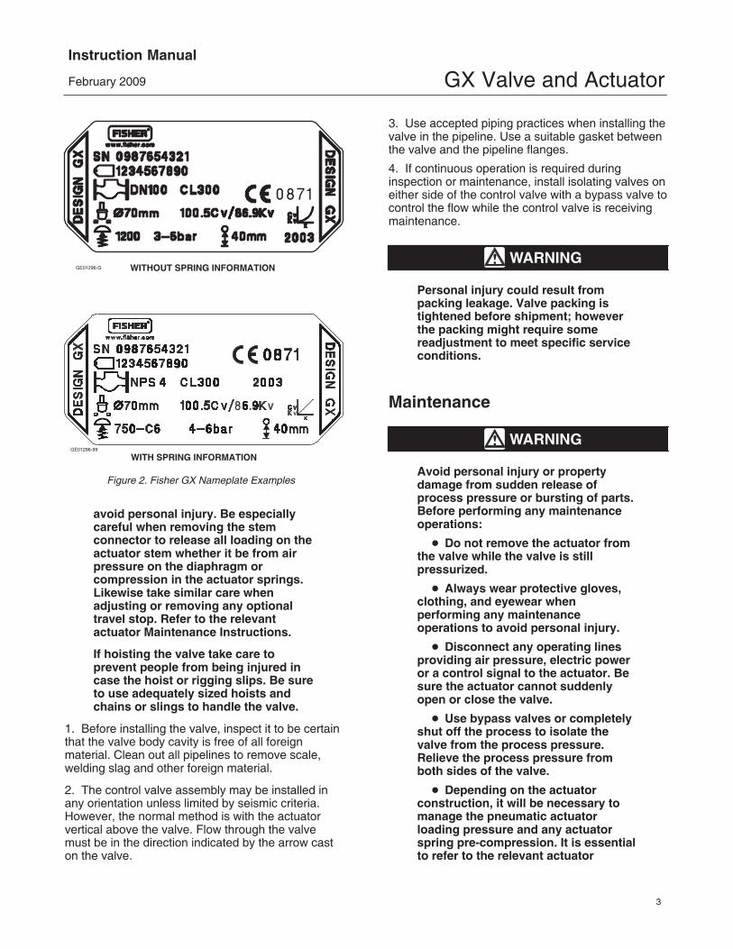
Figure 2. Fisher GX Nameplate Examples
GE01296-99
WITH SPRING INFORMATION
WITHOUT SPRING INFORMATIONGE01296-G
avoid personal injury. Be especiallycareful when removing the stemconnector to release all loading on theactuator stem whether it be from airpressure on the diaphragm orcompression in the actuator springs.Likewise take similar care whenadjusting or removing any optionaltravel stop. Refer to the relevantactuator Maintenance Instructions.
If hoisting the valve take care toprevent people from being injured incase the hoist or rigging slips. Be sureto use adequately sized hoists andchains or slings to handle the valve.
1. Before installing the valve, inspect it to be certainthat the valve body cavity is free of all foreignmaterial. Clean out all pipelines to remove scale,welding slag and other foreign material.
2. The control valve assembly may be installed inany orientation unless limited by seismic criteria.However, the normal method is with the actuatorvertical above the valve. Flow through the valvemust be in the direction indicated by the arrow caston the valve.
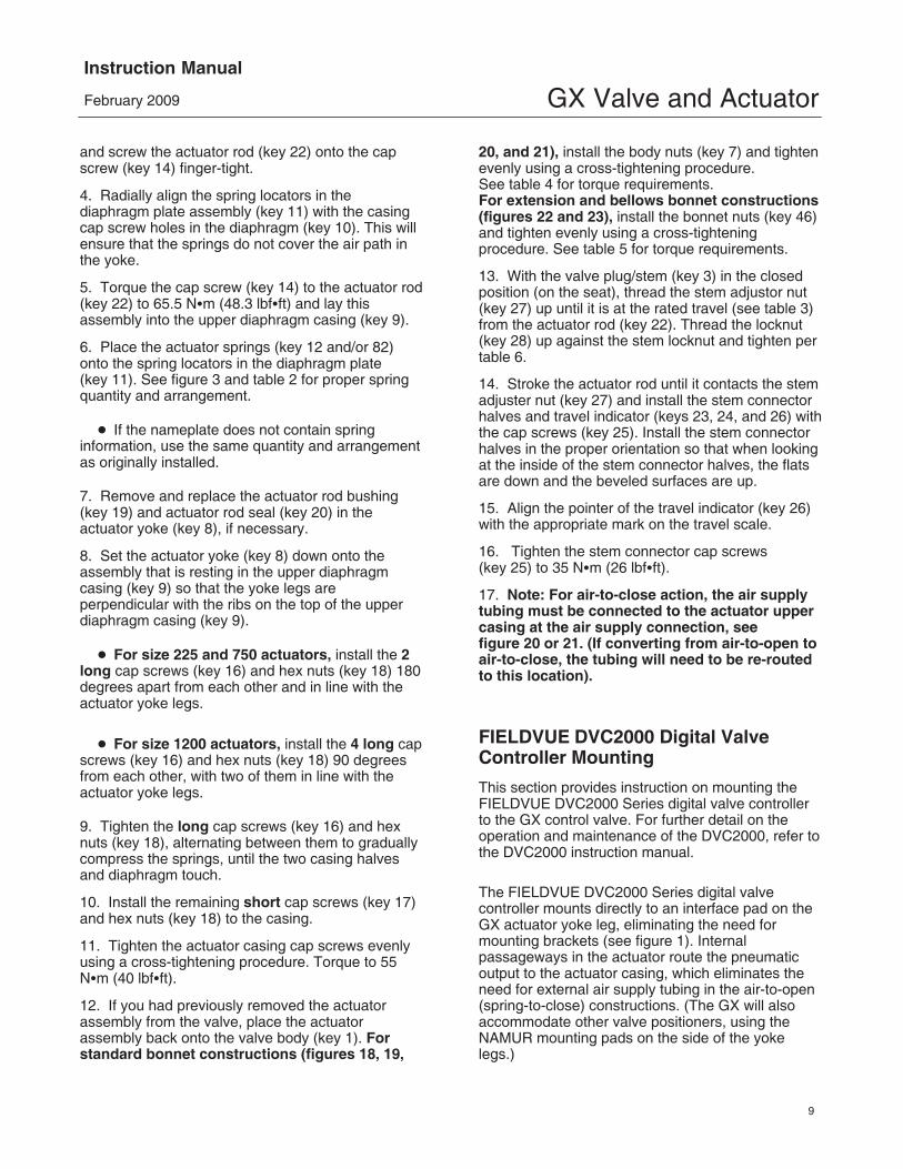
3. Use accepted piping practices when installing thevalve in the pipeline. Use a suitable gasket betweenthe valve and the pipeline flanges.
4. If continuous operation is required duringinspection or maintenance, install isolating valves oneither side of the control valve with a bypass valve tocontrol the flow while the control valve is receivingmaintenance.
WARNING
Personal injury could result frompacking leakage. Valve packing istightened before shipment; howeverthe packing might require somereadjustment to meet specific serviceconditions.
Maintenance
WARNING
Avoid personal injury or propertydamage from sudden release ofprocess pressure or bursting of parts.Before performing any maintenanceoperations:
� Do not remove the actuator fromthe valve while the valve is stillpressurized.
� Always wear protective gloves,clothing, and eyewear whenperforming any maintenanceoperations to avoid personal injury.
� Disconnect any operating linesproviding air pressure, electric poweror a control signal to the actuator. Besure the actuator cannot suddenlyopen or close the valve.
� Use bypass valves or completelyshut off the process to isolate thevalve from the process pressure.Relieve the process pressure fromboth sides of the valve.
� Depending on the actuatorconstruction, it will be necessary tomanage the pneumatic actuatorloading pressure and any actuatorspring pre-compression. It is essentialto refer to the relevant actuator
GX Valve and ActuatorInstruction Manual
February 2009
4
instructions in this manual to ensuresafe removal of the actuator from thevalve.
� Use lock-out procedures to besure that the above measures stay ineffect while you work on theequipment.
� The valve packing box maycontain process fluids that arepressurized, even when the valve hasbeen removed from the pipeline.Process fluids may spray out underpressure when removing the packinghardware or packing rings, or whenloosening the packing box pipe plug.
� Check with your process or safetyengineer for any additional measuresthat must be taken to protect againstprocess media.
Note
Whenever a gasket seal is disturbedby removing or shifting gasketedparts, install a new gasket duringreassembly. This ensures a goodgasket seal because the used gasketmay not seal properly.
Actuator Maintenance
The following sections provide procedures foractuator maintenance. Refer to figures 18, 19, 20,and 21.
The actuator soft parts may require periodicreplacement. This includes the diaphragm (key 10),actuator rod bushing (key 19), and the actuator rodseal (key 20).
If the actuator stroking direction (air-to-open orair-to-close) is unknown, refer to the nameplate ontop of the actuator casing and figure 2.
There are several optional actuator constructions,depending on supply pressure. Refer to thenameplate on the top of the actuator to determinethe construction installed. Refer to figure 3 and table 2 for proper spring configuration.
Note
Older GX actuator nameplates do notcontain spring configurationinformation. If you require replacementsprings or wish to switch to anoptional actuator construction, consultyour Emerson Process Managementsales office.
Note
When the GX actuator is equipped withthe integrated FIELDVUE DVC2000Series digital valve controller (figure1), additional considerations may berequired. Refer to the FIELDVUEDVC2000 Digital Valve ControllerMounting section of this manual foradditional instruction.
Actuator Disassembly (For Air-to-OpenConstructions - see figures 18 or 19)1. Connect a separate air supply to the lowerdiaphragm casing via the air supply connection onthe yoke (as shown in figure 18 or 19) and applysufficient air pressure to raise the valve plug/stem offthe seat to mid-travel.
2. Remove the stem connector nut half (key 23),stem connector bolt half (key 24), and travelindicator (key 26).
3. Push the valve plug/stem (key 3) down until itcontacts the seat.
4. Loosen the locknut (key 28) and thread the stemadjustor nut (key 27) down until it clears the top ofthe valve plug/stem (key 3).
5. Shut off the air pressure and disconnect theseparate air supply to the lower diaphragm casing(as shown in figure 18 or 19).
WARNING
To avoid personal injury or propertydamage due to actuator springs (keys12 and 82) being under compression,remove the long cap screws (key 16)last.
The upper actuator casing may remainfixed to the diaphragm and lowercasing during disassembly, even if thecasing cap screws have beenloosened. If this happens, the actuator
GX Valve and ActuatorInstruction Manual
February 2009
5
springs are still under compression.The upper casing could suddenlycome loose and jump, due to thecompressed energy of the springs. Ifthe upper casing is stuck to thediaphragm and lower casing when youbegin loosening the casing capscrews, pry the casings apart with aprying tool. Always ensure that thesprings are dispersing energy and theupper casing is moving against thelong bolts during disassembly.
6. Remove the short actuator casing cap screwsand hex nuts (keys 17 and 18) first. Once thesehave been removed from the actuator assembly,carefully remove the long actuator cap screws andhex nuts (keys 16 and 18), alternating between themto gradually release the spring energy(compression).
8. Lift off the actuator stem/diaphragm assembly(includes keys 22, 11, 10, 14, 13, and 15) andremove the cap screw (key 14), actuator spacer (key 13), actuator rod (key 22), and washer (key 15).
9. Replace the diaphragm (key 10), actuator rodbushing (key 19), and actuator rod seal (key 20), asneeded.
Actuator Disassembly (For Air-to-CloseConstructions - see figure 20 or 21)1. Remove the stem connector nut half (key 23),stem connector bolt half (key 24), and travelindicator (key 26).
WARNING
To avoid personal injury or propertydamage due to actuator springs (key
12) being under compression, removethe long cap screws (key 16) last.
The upper actuator casing may remainfixed to the diaphragm and lowercasing during disassembly, even if thecasing cap screws have beenloosened. If this happens, the actuatorsprings are still under compression.The upper casing could suddenlycome loose and jump, due to thecompressed energy of the springs. Ifthe upper casing is stuck to thediaphragm and lower casing when youbegin loosening the casing capscrews, pry the casings apart with aprying tool. Always ensure that thesprings are dispersing energy and theupper casing is moving against thelong bolts during disassembly.
2. Remove the short actuator casing cap screwsand hex nuts (keys 17 and 18) first. Once thesehave been removed from the actuator assembly,carefully remove the long actuator cap screws andhex nuts (keys 16 and 18), alternating between themto gradually release the spring energy(compression).
3. Remove the upper diaphragm casing (key 9).
4. Lift off the actuator stem/diaphragm assembly(includes keys 22, 11, 10, 14, 13, and 15) andremove the cap screw (key 14), actuator spacer (key 13), actuator rod (key 22), and washer (key 15).
5. Remove the actuator springs (key 12 and/or 82).
6. Replace the diaphragm (key 10), actuator rodbushing (key 19), and actuator rod seal (key 20), asneeded.
GX Valve and ActuatorInstruction Manual
February 2009
6
GG00398-A
Figure 3. Spring Configuration
GX Valve and ActuatorInstruction Manual
February 2009
7
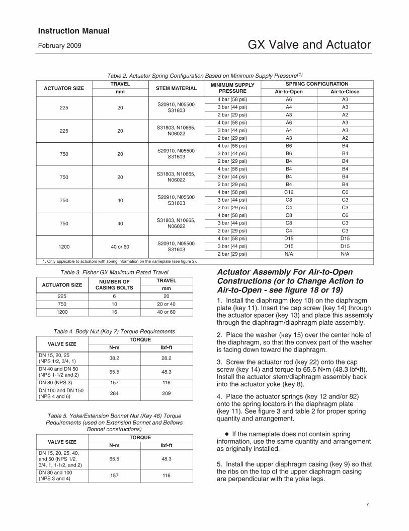
Table 2. Actuator Spring Configuration Based on Minimum Supply Pressure(1)
ACTUATOR SIZETRAVEL
STEM MATERIALMINIMUM SUPPLY
PRESSURESPRING CONFIGURATION
mm Air-to-Open Air-to-Close
225 20S20910, N05500
S31603
4 bar (58 psi) A6 A3
3 bar (44 psi) A4 A3
2 bar (29 psi) A3 A2
225 20S31803, N10665,
N06022
4 bar (58 psi) A6 A3
3 bar (44 psi) A4 A3
2 bar (29 psi) A3 A2
750 20S20910, N05500
S31603
4 bar (58 psi) B6 B4
3 bar (44 psi) B6 B4
2 bar (29 psi) B4 B4
750 20S31803, N10665,
N06022
4 bar (58 psi) B4 B4
3 bar (44 psi) B4 B4
2 bar (29 psi) B4 B4
750 40S20910, N05500
S31603
4 bar (58 psi) C12 C6
3 bar (44 psi) C8 C3
2 bar (29 psi) C4 C3
750 40S31803, N10665,
N06022
4 bar (58 psi) C8 C6
3 bar (44 psi) C8 C3
2 bar (29 psi) C4 C3
1200 40 or 60S20910, N05500
S31603
4 bar (58 psi) D15 D15
3 bar (44 psi) D15 D15
2 bar (29 psi) N/A N/A1. Only applicable to actuators with spring information on the nameplate (see figure 2).
Table 3. Fisher GX Maximum Rated Travel
ACTUATOR SIZENUMBER OF
CASING BOLTSTRAVEL
mm
225 6 20
750 10 20 or 40
1200 16 40 or 60
Table 4. Body Nut (Key 7) Torque Requirements
VALVE SIZETORQUE
N�m lbf�ft
DN 15, 20, 25 (NPS 1/2, 3/4, 1)
38.2 28.2
DN 40 and DN 50(NPS 1-1/2 and 2)
65.5 48.3
DN 80 (NPS 3) 157 116
DN 100 and DN 150(NPS 4 and 6)
284 209
Table 5. Yoke/Extension Bonnet Nut (Key 46) TorqueRequirements (used on Extension Bonnet and Bellows
Actuator Assembly For Air-to-OpenConstructions (or to Change Action toAir-to-Open - see figure 18 or 19)1. Install the diaphragm (key 10) on the diaphragmplate (key 11). Insert the cap screw (key 14) throughthe actuator spacer (key 13) and place this assemblythrough the diaphragm/diaphragm plate assembly.
2. Place the washer (key 15) over the center hole ofthe diaphragm, so that the convex part of the washeris facing down toward the diaphragm.
3. Screw the actuator rod (key 22) onto the capscrew (key 14) and torque to 65.5 N�m (48.3 lbf�ft).Install the actuator stem/diaphragm assembly backinto the actuator yoke (key 8).
4. Place the actuator springs (key 12 and/or 82)onto the spring locators in the diaphragm plate (key 11). See figure 3 and table 2 for proper springquantity and arrangement.
� If the nameplate does not contain springinformation, use the same quantity and arrangementas originally installed.
5. Install the upper diaphragm casing (key 9) so thatthe ribs on the top of the upper diaphragm casingare perpendicular with the yoke legs.
GX Valve and ActuatorInstruction Manual
February 2009
8
� For size 225 and 750 actuators, install the 2long cap screws (key 16) and hex nuts (key 18) 180degrees apart from each other and in line with theactuator yoke legs.
� For size 1200 actuators, install the 4 long capscrews (key 16) and hex nuts (key 18) 90 degreesfrom each other, with two of them in line with theactuator yoke legs.
6. Tighten the long cap screws (key 16) and hexnuts (key 18), alternating between them to graduallycompress the springs, until the two casing halvesand diaphragm touch.
7. Install the remaining short cap screws (key 17)and hex nuts (key 18) to the casing.
8. Tighten the actuator casing cap screws evenlyusing a cross-tightening procedure. Torque to 55N�m (40 lbf�ft).
9. If you had previously removed the actuatorassembly from the valve, place the actuatorassembly back onto the valve body (key 1). Installthe four body nuts (key 7), but tighten them onlyfinger-tight.
10. Connect a separate air supply to the actuator airsupply connection (as shown on the yoke in figure18 or 19) and apply sufficient air pressure to raisethe actuator rod (key 22) to the travel stop.
Note: If converting from air-to-close toair-to-open action, first move the vent cap (key 21) from the air supply connection on theyoke leg (see figure 20 or 21) to the top of thecasing (see figure 18 or 19).
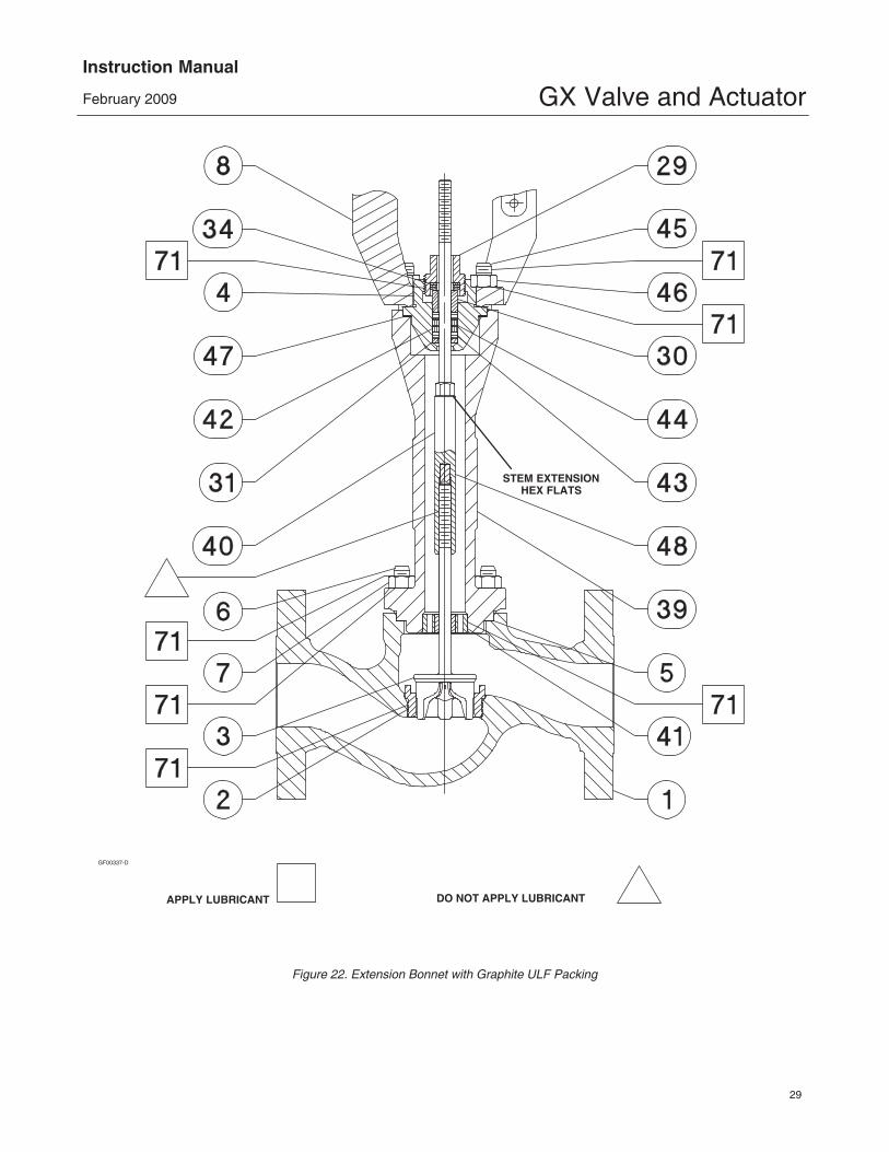
11. For standard bonnet constructions (figures 18, 19, 20, and 21), tighten the body nuts(key 7) evenly using a cross-tightening procedure.See table 4 for torque requirements.For extension and bellows bonnet constructions(figures 22 and 23), tighten the bonnet nuts (key 46) evenly using a cross-tightening procedure.See table 5 for torque requirements.
12. With the valve plug/stem (key 3) on the seat,thread the stem adjustor nut (key 27) up until it is therated travel distance specified in table 3 from theactuator rod (key 22). Thread the locknut (key 28) upagainst the stem locknut and tighten per table 6.
Table 6. Stem Connector Torque Values
PARTSTEM
MATERIALTORQUE
N�m Lbf�ft
M8 StemConnector
Cap ScrewsAll 35 26
M10 StemConnector
Jam Nut (Rie4606 Coated)
S31603,S20910,N05500
48 35
N06022,S31803,N10665
35 26
M14 StemConnectorJam Nut
S31603,S20910,N05500
175 129
N06022,S31803,N10665
138 102
13. Stroke the actuator rod until it contacts the stemadjuster nut (key 27) and install the stem connectorhalves and travel indicator (keys 23, 24, and 26) withthe cap screws (key 25). Install the stem connectorhalves in the proper orientation so that when lookingat the inside of the stem connector halves, the flatsare down and the beveled surfaces are up.
14. Align the pointer of the travel indicator (key 26)with the appropriate mark on the travel scale.
15. Tighten the stem connector cap screws (key 25) to 35 N�m (26 lbf�ft).
16. Release the actuator pressure.
17. Note: For air-to-open action, the air supplytubing must be connected to the actuator yoke atthe air supply connection, see figure 18 or 19. (Ifconverting from air-to-close to air-to-open, thetubing will need to be re-routed to this location).
Actuator Assembly For Air-to-CloseConstructions (or to Change Action toAir-to-Close - see figure 20 or 21)1. Position the upper diaphragm casing (key 9)upside down on the bench so that it lays flat and notoff balance.
Note: If converting from air-to-open toair-to-close action, first move the vent cap (key 21) from the top of the casing (see figure 18or 19) and thread into the air supply connectionon the yoke leg (see figure 20 or 21).
2. Install the diaphragm (key 10) on the diaphragmplate (key 11). Place the washer (key 15) over thecenter hole of the diaphragm, so that the convex partof the washer is facing down toward the diaphragm.
3. Insert the cap screw (key 14) through the washerand diaphragm, install the actuator spacer (key 13),
GX Valve and ActuatorInstruction Manual
February 2009
9
and screw the actuator rod (key 22) onto the capscrew (key 14) finger-tight.
4. Radially align the spring locators in thediaphragm plate assembly (key 11) with the casingcap screw holes in the diaphragm (key 10). This willensure that the springs do not cover the air path inthe yoke.
5. Torque the cap screw (key 14) to the actuator rod(key 22) to 65.5 N�m (48.3 lbf�ft) and lay thisassembly into the upper diaphragm casing (key 9).
6. Place the actuator springs (key 12 and/or 82)onto the spring locators in the diaphragm plate (key 11). See figure 3 and table 2 for proper springquantity and arrangement.
� If the nameplate does not contain springinformation, use the same quantity and arrangementas originally installed.
7. Remove and replace the actuator rod bushing(key 19) and actuator rod seal (key 20) in theactuator yoke (key 8), if necessary.
8. Set the actuator yoke (key 8) down onto theassembly that is resting in the upper diaphragmcasing (key 9) so that the yoke legs areperpendicular with the ribs on the top of the upperdiaphragm casing (key 9).
� For size 225 and 750 actuators, install the 2long cap screws (key 16) and hex nuts (key 18) 180degrees apart from each other and in line with theactuator yoke legs.
� For size 1200 actuators, install the 4 long capscrews (key 16) and hex nuts (key 18) 90 degreesfrom each other, with two of them in line with theactuator yoke legs.
9. Tighten the long cap screws (key 16) and hexnuts (key 18), alternating between them to graduallycompress the springs, until the two casing halvesand diaphragm touch.
10. Install the remaining short cap screws (key 17)and hex nuts (key 18) to the casing.
11. Tighten the actuator casing cap screws evenlyusing a cross-tightening procedure. Torque to 55N�m (40 lbf�ft).
12. If you had previously removed the actuatorassembly from the valve, place the actuatorassembly back onto the valve body (key 1). Forstandard bonnet constructions (figures 18, 19,
20, and 21), install the body nuts (key 7) and tightenevenly using a cross-tightening procedure. See table 4 for torque requirements.For extension and bellows bonnet constructions(figures 22 and 23), install the bonnet nuts (key 46)and tighten evenly using a cross-tighteningprocedure. See table 5 for torque requirements.
13. With the valve plug/stem (key 3) in the closedposition (on the seat), thread the stem adjustor nut(key 27) up until it is at the rated travel (see table 3)from the actuator rod (key 22). Thread the locknut(key 28) up against the stem locknut and tighten pertable 6.
14. Stroke the actuator rod until it contacts the stemadjuster nut (key 27) and install the stem connectorhalves and travel indicator (keys 23, 24, and 26) withthe cap screws (key 25). Install the stem connectorhalves in the proper orientation so that when lookingat the inside of the stem connector halves, the flatsare down and the beveled surfaces are up.
15. Align the pointer of the travel indicator (key 26)with the appropriate mark on the travel scale.
16. Tighten the stem connector cap screws (key 25) to 35 N�m (26 lbf�ft).
17. Note: For air-to-close action, the air supplytubing must be connected to the actuator uppercasing at the air supply connection, see figure 20 or 21. (If converting from air-to-open toair-to-close, the tubing will need to be re-routedto this location).
FIELDVUE DVC2000 Digital ValveController Mounting
This section provides instruction on mounting theFIELDVUE DVC2000 Series digital valve controllerto the GX control valve. For further detail on theoperation and maintenance of the DVC2000, refer tothe DVC2000 instruction manual.
The FIELDVUE DVC2000 Series digital valvecontroller mounts directly to an interface pad on theGX actuator yoke leg, eliminating the need formounting brackets (see figure 1). Internalpassageways in the actuator route the pneumaticoutput to the actuator casing, which eliminates theneed for external air supply tubing in the air-to-open(spring-to-close) constructions. (The GX will alsoaccommodate other valve positioners, using theNAMUR mounting pads on the side of the yokelegs.)
GX Valve and ActuatorInstruction Manual
February 2009
10
POLE PIECES
M8 MOUNTING BOLTS
A: EXTERNAL PNEUMATICOUTPUT PORT (1/4 NPTOR G1/4 PLUG)
B: INTEGRAL MOUNTINGPNEUMATIC OUTPUTPORT (R1/8 PLUG)
FOR AIR-TO-OPEN, INSTALL THE O-RING SEALBEFORE MOUNTING TO THE GX ACTUATOR
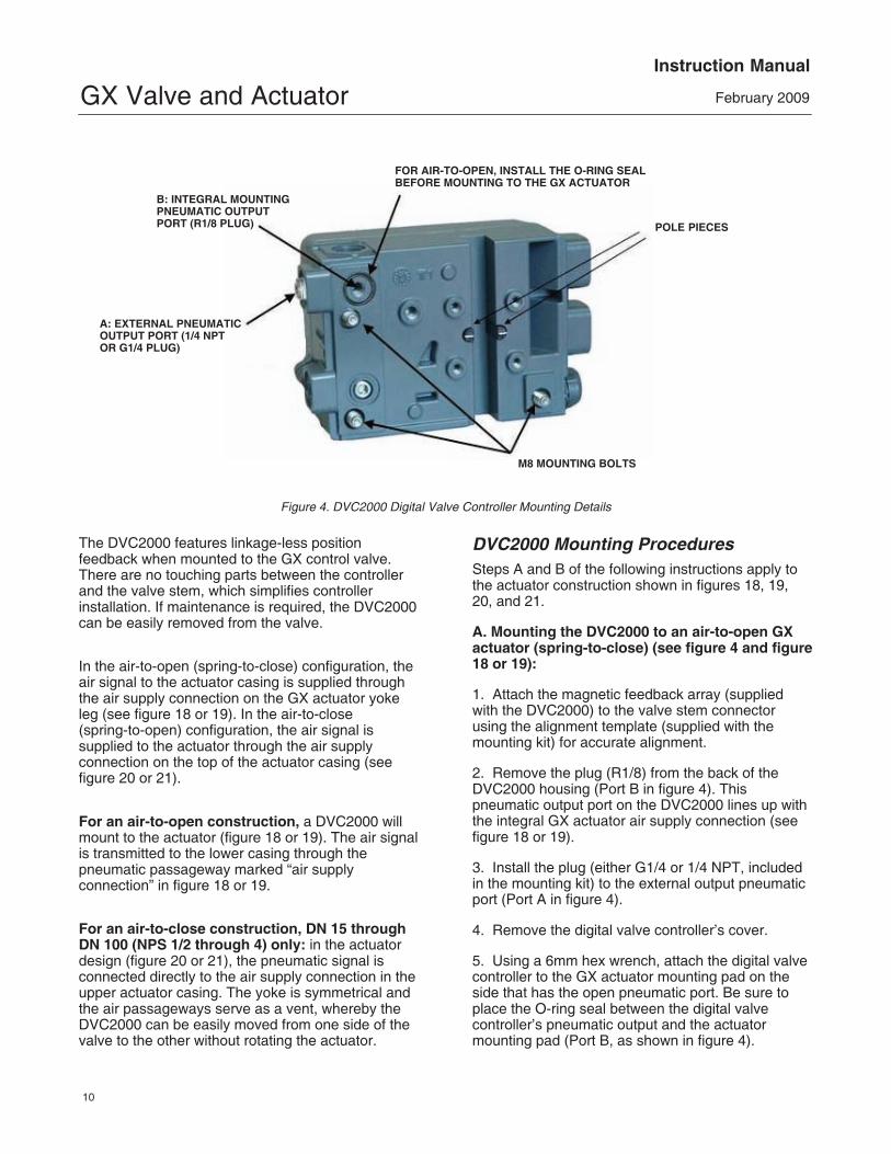
Figure 4. DVC2000 Digital Valve Controller Mounting Details
The DVC2000 features linkage-less positionfeedback when mounted to the GX control valve.There are no touching parts between the controllerand the valve stem, which simplifies controllerinstallation. If maintenance is required, the DVC2000can be easily removed from the valve.
In the air-to-open (spring-to-close) configuration, theair signal to the actuator casing is supplied throughthe air supply connection on the GX actuator yokeleg (see figure 18 or 19). In the air-to-close(spring-to-open) configuration, the air signal issupplied to the actuator through the air supplyconnection on the top of the actuator casing (seefigure 20 or 21).
For an air-to-open construction, a DVC2000 willmount to the actuator (figure 18 or 19). The air signalis transmitted to the lower casing through thepneumatic passageway marked “air supplyconnection” in figure 18 or 19.
For an air-to-close construction, DN 15 throughDN 100 (NPS 1/2 through 4) only: in the actuatordesign (figure 20 or 21), the pneumatic signal isconnected directly to the air supply connection in theupper actuator casing. The yoke is symmetrical andthe air passageways serve as a vent, whereby theDVC2000 can be easily moved from one side of thevalve to the other without rotating the actuator.
DVC2000 Mounting ProceduresSteps A and B of the following instructions apply tothe actuator construction shown in figures 18, 19,20, and 21.
A. Mounting the DVC2000 to an air-to-open GXactuator (spring-to-close) (see figure 4 and figure18 or 19):
1. Attach the magnetic feedback array (suppliedwith the DVC2000) to the valve stem connectorusing the alignment template (supplied with themounting kit) for accurate alignment.
2. Remove the plug (R1/8) from the back of theDVC2000 housing (Port B in figure 4). Thispneumatic output port on the DVC2000 lines up withthe integral GX actuator air supply connection (seefigure 18 or 19).
3. Install the plug (either G1/4 or 1/4 NPT, includedin the mounting kit) to the external output pneumaticport (Port A in figure 4).
4. Remove the digital valve controller’s cover.
5. Using a 6mm hex wrench, attach the digital valvecontroller to the GX actuator mounting pad on theside that has the open pneumatic port. Be sure toplace the O-ring seal between the digital valvecontroller’s pneumatic output and the actuatormounting pad (Port B, as shown in figure 4).
GX Valve and ActuatorInstruction Manual
February 2009
11
Pneumatic tubing is not required because the airpassages are internal to the actuator. Also, installthe insulating gaskets around the mounting bolts.
6. Check for clearance between the magnetassembly and the DVC2000 feedback slot. Themagnet assembly should be positioned such that theindex mark in the feedback slot of the DVC2000housing is between the valid range on the magnetassembly throughout the range of travel. (See figure 4).
B. For air-to-close GX actuator (spring-to-open)(see figure 4 and figure 20 or 21):
1. Attach the magnetic feedback array (suppliedwith the DVC2000) to the valve stem connectorusing the alignment template (supplied with themounting kit) for accurate alignment.
2. In the air-to-close configuration it is required thatan R1/8 plug be installed into the integral mountpneumatic port on the back of the DVC2000 housing(Port B of figure 4).
3. Remove the digital valve controller’s cover.
4. Using a 6mm hex wrench, attach the digital valvecontroller to the GX actuator mounting pad.
Note
The O-ring seal and G1/4 or 1/4 NPTplugs (supplied in the mounting kit)are not used with this actuatorconstruction.
5. Check for clearance between the magnetassembly and the DVC2000 feedback slot. Themagnet assembly should be positioned such that theindex mark on the pole pieces (back of the controllerhousing) is between the marks on the magnetassembly throughout the range of travel. (See figure 4.)
6. Install tubing between the external pneumaticoutput connection of the DVC2000 (Port A of figure 4) to the air supply connection (see figure 20or 21) on top of the actuator casing.
When changing actuator action:
When field converting a GX actuator fromair-to-open to air-to-close closed (or vice-versa), youwill need to change the plugs for the pneumaticpassages in the DVC2000 housing.
� To convert from air-to-close to air-to-open(spring-to-close), remove the R1/8 pneumatic plugon the back of the DVC2000 housing and install anO-ring (Port B of figure 4). Plug the externalpneumatic output with a 1/4 NPT or G1/4 plug(depending on the housing version). (Port A of figure 4.)
� To convert from air-to-open to air-to-close(spring-to-open), remove the external pneumaticplug (1/4 NPT or G1/4 plug, depending on thehousing version from Port A of figure 4). Install anR1/8 plug on the back of the DVC2000 housing (PortB of figure 4). Install tubing between the pneumaticoutput connection of the DVC2000 (Port A) to the airsupply connection on top of the actuator casing (seefigure 20 or 21).
Packing AdjustmentFor spring-loaded single PTFE V-ring packing (figure 15) or for Graphite ULF packing (figure 16),the Belleville spring pack (key 34) maintains asealing force on the packing. If leakage is detectedaround the packing follower (key 29) check to besure that the packing follower (key 29) is tight. Usinga wrench, tighten the packing follower (key 29) in 1/4turn intervals until the leakage is stopped. If leakagecannot be stopped in this manner, proceed to theReplacing Packing section in this manual.
Replacing PackingThis section provides instruction on replacingpacking in standard bonnets, extension bonnets, andbellows extension bonnets.
Isolate the control valve from the line pressure,release pressure from both sides of the valve bodyand drain the process media from both sides of thevalve. Shut off all pressure lines to the actuator andrelease all pressure from the actuator. Use lock-outprocedures to ensure that the above measures stayin effect while you work on the equipment.
1. For air-to-open constructions:
a. Connect a separate air supply to the lowerdiaphragm casing via the air supply connectionon the yoke (as shown in figure 18 or 19) andapply sufficient air pressure to raise the valveplug/stem off the seat to mid travel.
GX Valve and ActuatorInstruction Manual
February 2009
12
b. Remove the stem connector nut half (key 23),stem connector bolt half (key 24), and travelindicator (key 26).
c. Push the valve plug stem (key 3) down until itcontacts the seat.
d. Loosen the locknut (key 28) and thread thestem adjustor nut (key 27) down until it clears thetop of the valve plug stem (key 3).
e. Shut off the air pressure and disconnect theseparate air supply to the lower diaphragmcasing (as shown in figure 18 or 19).
2. For air-to-close constructions, as shown infigure 20 or 21, remove the stem connector nut half(key 23), stem connector bolt half (key 24), andtravel indicator (key 26).
WARNING
To avoid personal injury or propertydamage by uncontrolled movement ofthe actuator yoke (key 8), loosen thebody/yoke nuts (figures 18, 19, 20, and21, key 7) or bonnet/yoke nuts (figures22 and 23, key 46) by following theinstructions in the next step. Do notremove a stuck actuator yoke bypulling on it with equipment that canstretch or store energy in any othermanner. The sudden release of storedenergy can cause uncontrolledmovement of the actuator yoke.
Note
The following step also providesadditional assurance that the valvebody fluid pressure has been relieved.
3. For standard bonnet constructions (figures18, 19, 20, and 21), body nuts (key 7) attach theactuator yoke (key 8) to the valve body (key 1).Loosen these nuts approximately 3mm (1/8 inch).
For extension and bellows bonnet constructions,bonnet nuts (key 46) attach the actuator yoke (key 8)
to the extension bonnet (key 39). Loosen these nutsapproximately 3mm (1/8 inch).
4. Then loosen the valve-to-yoke gasketed joint byeither rocking the actuator yoke or prying betweenthe valve and actuator yoke. Work the prying toolaround the actuator yoke until it loosens.
WARNING
If there is evidence of process fluidunder pressure leaking from the joint,retighten the valve body/joint nuts andreturn to the Warning at the beginningof the Maintenance section to ensureproper steps have been taken toisolate the valve and relieve processpressure.
5. If no fluid leaks from the joint, loosen the packingfollower (key 29) two turns to relieve the packingcompression load.
6. For standard bonnet constructions (figures18, 19, 20, and 21), remove the body nuts (key 7)completely.For extension and bellows bonnet constructions(figures 22 and 23), remove the bonnet nuts (key 46) completely.
CAUTION
To avoid property damage, place theactuator yoke on a protective surface,as described in the followingprocedure.
7. Carefully lift off the actuator yoke and set it on aprotective surface to prevent damage.For standard bonnet constructions, if the bonnet(key 4) together with the valve stem plug assemblyhas a tendency to lift with the actuator yoke, ensureit does not drop from the actuator.For extension and bellows constructions, ensurethe bonnet (key 4) does not lift with the actuatoryoke.For DN150 balanced constructions, if the bonnet,guide sleeve, or valve stem assembly have atendency to lift with the actuator yoke, ensure theydo not drop from the actuator.
GX Valve and ActuatorInstruction Manual
February 2009
13
GE02918-6
A A
G
B
B
H
D F
E
C C
C
D F
E
DN15, 20, 25(NPS 1/2, 3/4, 1)
DN40, 50, 80, 100(NPS 1-1/2, 2, 3, 4)
A
B
E
F
C
C
J
KD
DN150(NPS 6)
DN25 Cav III(NPS 1)
GG01215
C
�F
�G
D
EH
B
A
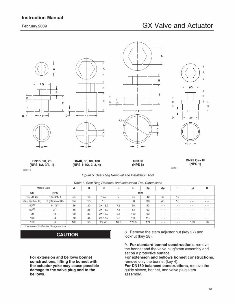
Figure 5. Seat Ring Removal and Installation Tool
Table 7. Seat Ring Removal and Installation Tool Dimensions
9. For standard bonnet constructions, removethe bonnet and the valve plug/stem assembly andset on a protective surface.For extension and bellows bonnet constructions,remove only the bonnet (key 4).For DN150 balanced constructions, remove theguide sleeve, bonnet, and valve plug stemassembly.
GX Valve and ActuatorInstruction Manual
February 2009
14
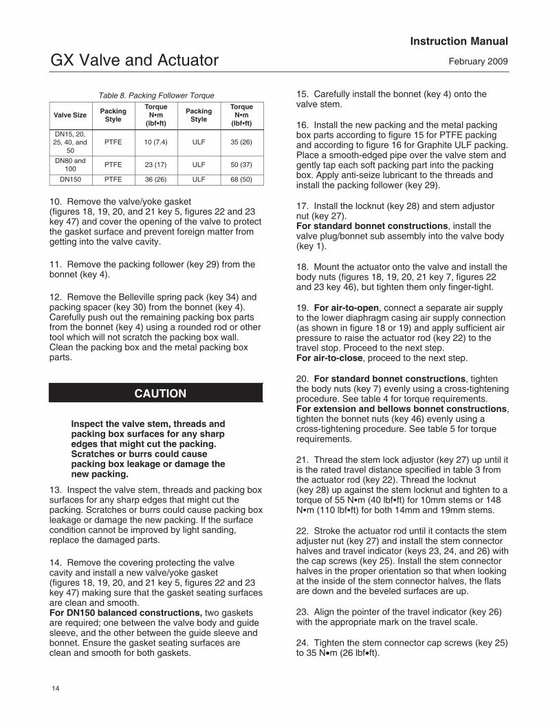
Table 8. Packing Follower Torque
Valve Size PackingStyle
TorqueN�m
(lbf�ft)
PackingStyle
TorqueN�m
(lbf�ft)
DN15, 20,25, 40, and
50PTFE 10 (7.4) ULF 35 (26)
DN80 and100
PTFE 23 (17) ULF 50 (37)
DN150 PTFE 36 (26) ULF 68 (50)
10. Remove the valve/yoke gasket (figures 18, 19, 20, and 21 key 5, figures 22 and 23key 47) and cover the opening of the valve to protectthe gasket surface and prevent foreign matter fromgetting into the valve cavity.
11. Remove the packing follower (key 29) from thebonnet (key 4).
12. Remove the Belleville spring pack (key 34) andpacking spacer (key 30) from the bonnet (key 4).Carefully push out the remaining packing box partsfrom the bonnet (key 4) using a rounded rod or othertool which will not scratch the packing box wall.Clean the packing box and the metal packing boxparts.
CAUTION
Inspect the valve stem, threads andpacking box surfaces for any sharpedges that might cut the packing.Scratches or burrs could causepacking box leakage or damage thenew packing.
13. Inspect the valve stem, threads and packing boxsurfaces for any sharp edges that might cut thepacking. Scratches or burrs could cause packing boxleakage or damage the new packing. If the surfacecondition cannot be improved by light sanding,replace the damaged parts.
14. Remove the covering protecting the valve cavity and install a new valve/yoke gasket (figures 18, 19, 20, and 21 key 5, figures 22 and 23key 47) making sure that the gasket seating surfacesare clean and smooth.For DN150 balanced constructions, two gasketsare required; one between the valve body and guidesleeve, and the other between the guide sleeve andbonnet. Ensure the gasket seating surfaces areclean and smooth for both gaskets.
15. Carefully install the bonnet (key 4) onto thevalve stem.
16. Install the new packing and the metal packingbox parts according to figure 15 for PTFE packingand according to figure 16 for Graphite ULF packing.Place a smooth-edged pipe over the valve stem andgently tap each soft packing part into the packingbox. Apply anti-seize lubricant to the threads andinstall the packing follower (key 29).
17. Install the locknut (key 28) and stem adjustornut (key 27).For standard bonnet constructions, install thevalve plug/bonnet sub assembly into the valve body(key 1).
18. Mount the actuator onto the valve and install thebody nuts (figures 18, 19, 20, 21 key 7, figures 22and 23 key 46), but tighten them only finger-tight.
19. For air-to-open, connect a separate air supplyto the lower diaphragm casing air supply connection(as shown in figure 18 or 19) and apply sufficient airpressure to raise the actuator rod (key 22) to thetravel stop. Proceed to the next step.For air-to-close, proceed to the next step.
20. For standard bonnet constructions, tightenthe body nuts (key 7) evenly using a cross-tighteningprocedure. See table 4 for torque requirements.For extension and bellows bonnet constructions,tighten the bonnet nuts (key 46) evenly using across-tightening procedure. See table 5 for torquerequirements.
21. Thread the stem lock adjustor (key 27) up until itis the rated travel distance specified in table 3 fromthe actuator rod (key 22). Thread the locknut (key 28) up against the stem locknut and tighten to atorque of 55 N�m (40 lbf�ft) for 10mm stems or 148N�m (110 lbf�ft) for both 14mm and 19mm stems.
22. Stroke the actuator rod until it contacts the stemadjuster nut (key 27) and install the stem connectorhalves and travel indicator (keys 23, 24, and 26) withthe cap screws (key 25). Install the stem connectorhalves in the proper orientation so that when lookingat the inside of the stem connector halves, the flatsare down and the beveled surfaces are up.
23. Align the pointer of the travel indicator (key 26)with the appropriate mark on the travel scale.
24. Tighten the stem connector cap screws (key 25)to 35 N�m (26 lbf�ft).
GX Valve and ActuatorInstruction Manual
February 2009
15
Table 9. Seat Ring / Cage Torque RequirementsVALVE SIZE TORQUE
25. Tighten the packing follower (key 29) to thetorque specified in table 8.
Alternately, the packing follower can be tightened bythe following method:
a. Tighten the packing follower until the Bellevillesprings are compressed 100% (or completelyflat), as detected by a rapid increase in nuttorque.
b. For DN 15 through DN 100 (NPS 1/2through 4), loosen the packing follower 60� ofrotation.For DN 150 (NPS 6), loosen the packing follower90� of rotation.
26. For air-to-open, release the actuator pressure.
27. For air-to-open, ensure the vent (key 21) isinstalled into the upper diaphragm casing (see figure 18 or 19). For air-to-close, ensure the vent (key 21) isinstalled into the actuator yoke air supply connection(see figure 20 or 21).
Valve Trim MaintenanceKey numbers in this section refer to figures 18, 19,20, 21, 22, and 23.
Valve Trim Disassembly1. Remove the actuator and bonnet assembly asdescribed in the Replacing Packing section (steps 1through 10).
� For standard bonnet constructions (figures 18, 19, 20, 21, and 25), proceed to the Seat Ring / Cage Removal section.
� For extension bonnet constructions (figure 22), proceed to step 3.
� For bellows bonnet constructions (figure 23), proceed to step 2.
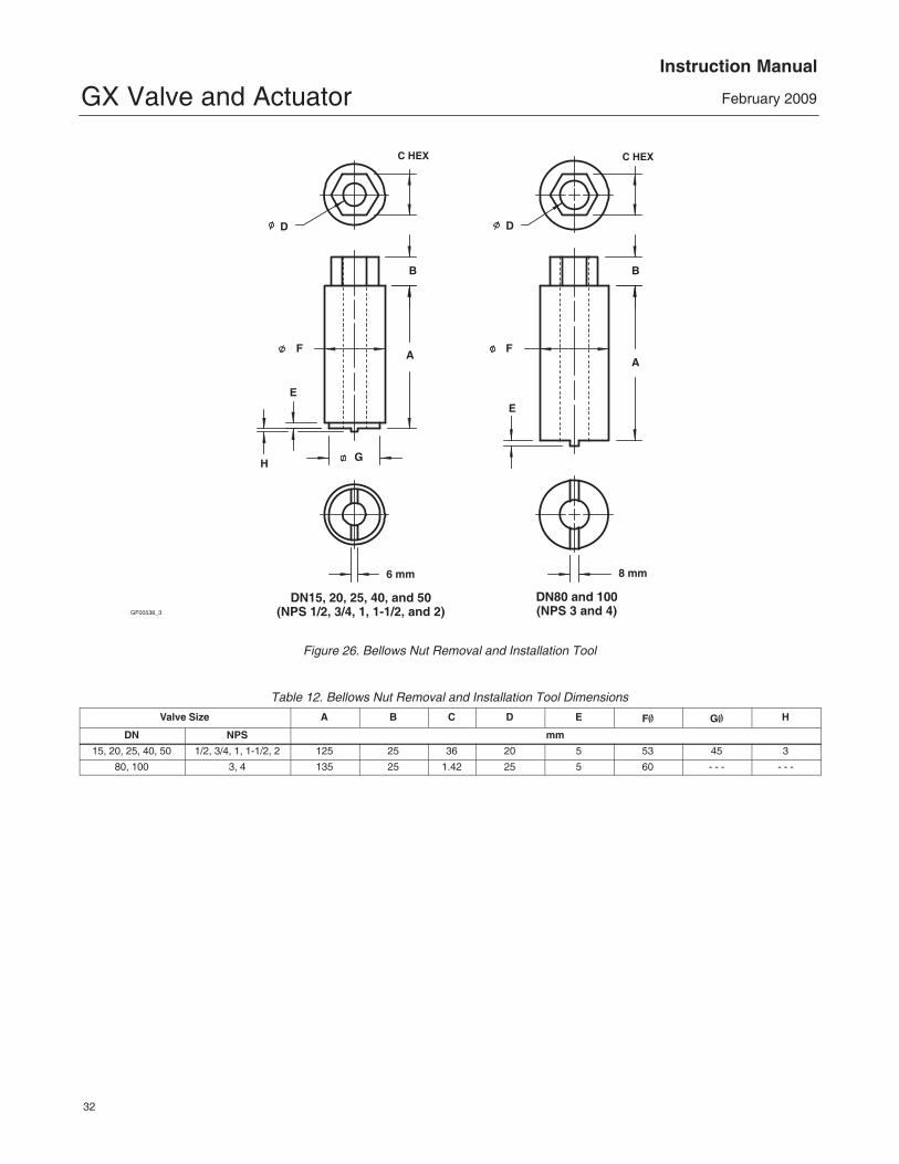
2. For bellows bonnet constructions (figure 23),use a bellows nut tool made according to thedimensions in figure 26 and table 12 to remove thebellows nut (key 51) as follows:
a. Insert the bellows nut tool into the extensionbonnet (key 39). Be certain the tool lugs areengaged in the corresponding recesses in thebellows nut.
b. Use a torque gun or driver having sufficienttorque capabilities according to table 11. Connectthe gun to a socket that snugly fits the hex headon the bellows nut tool.
c. Insert the socket onto the hex head of thebellows nut tool.
WARNING
Be careful to hold the torque gun,attached socket, and tool at rightangles to the bellows nut whenapplying torque. Tilting the gun andsocket while applying torque maycause the lugs on the bellows nut toolto suddenly disengage from the lugson the bellows nut thus causingpossible damage to the bellows nutand possible personal injury.
d. Remove the bellows nut (key 51).
3. For both extension and bellows bonnetconstructions: Body nuts (key 7) attach theextension bonnet (key 39) to the valve body (key 1).Loosen these nuts approximately 3mm (1/8 inch).Then loosen the extension bonnet-to-body gasketedjoint by either rocking the extension bonnet or pryingbetween the body and extension bonnet. Work the
GX Valve and ActuatorInstruction Manual
February 2009
16
prying tool around the extension bonnet until itloosens.
4. Remove the body nuts (key 7) completely andcarefully lift the extension bonnet (key 39), and valveplug/stem extension assembly (key 3, 40 and 48) orplug/bellows/stem extension assembly (key 3, 49and 48) from the top of the valve body.
5. Use a wrench to unscrew the plug/stem assembly(key 3) from the stem extension (key 40) or frombellows/stem assembly (key 49) as follows:
a. Insert the wrench onto the stem extension hexflats (see figures 22 and 23).
CAUTION
In the following procedure, takeprecautions to ensure the valve plugand stem finish are not damaged.
b. Clamp the plug/stem assembly (key 3) andholding it stable, unscrew the stem extension(key 40) or bellows/stem assembly (key 49). Takeprecautions to ensure the valve plug and stemfinish are not damaged.
Note: There is a stem assembly locking insert(figures 22 and 23, key 48) in the valve plug/stemextension assembly. It is possible this insertmay drop out during stem disassembly. If this isthe case, ensure it is retained for reassembly ofthe valve stem to the stem extension.
6. Remove the plug/stem assembly (key 3) andbellows/stem assembly (key 49) from the extensionbonnet. Remove the bellows gasket (key 50).
7. Proceed to the Seat Ring Removal section.
Seat Ring / Cage Removal
CAUTION
Use care to avoid damaging the gasketsealing surfaces.
The surface finish of the valve stem(key 3) is critical for making a goodpacking seal. The seating surfaces ofthe seat ring (key 2), cage (key 99), andthe valve plug (key 3) are critical for
tight shutoff and should therefore alsobe treated with care and properlyprotected.
1. Packing parts can be removed from the bonnet ifdesired. Replace these parts as described in thesection on Packing Maintenance.
2. Use a seat ring tool made according to thedimensions in figure 5 and table 7 to remove theseat ring (key 2) as follows:
a. Insert the tool into the valve body. Be certainthe tool lugs are engaged in the correspondingrecesses in the seat ring.
b. Use a torque gun or driver having sufficienttorque capabilities according to table 9. Connectthe gun to a socket that snugly fits the hex headon the seat ring tool.
c. Insert the socket onto the hex head of the seatring tool.
WARNING
Be careful to hold the torque gun,attached socket, and tool at rightangles to the seat ring when applyingtorque. Tilting the gun and socketwhile applying torque may cause thelugs on the seat ring tool to suddenlydisengage from the lugs on the seatring thus causing possible damage tothe seat ring and possible personalinjury.
3. Remove the seat ring (key 2) from the valvebody.
4. Inspect parts for wear or damage that wouldprevent proper operation of the valve body.
5. Replace trim parts as necessary.
Valve Trim AssemblyAssembly of Unbalanced Trim
Refer to figures 12, 18, 19, 20, 21, 22, 23, and 25.
1. Before installing the new seat ring / cage,thoroughly clean the threads in the valve body port.Apply suitable lubricant to the threads and to the 60�surface of the new seat ring (key 4). Screw the seat
GX Valve and ActuatorInstruction Manual
February 2009
17
ring into the valve body. Using the seat ring tool,tighten the seat ring and torque according to thevalues in table 9. Remove all excess lubricant aftertightening.
2. For standard bonnet constructions, performthe following. (Proceed to step 3 for extensionand bellows bonnets.)
a. Clean the body/yoke gasket seating surfacesand install a new body/yoke gasket (key 5).
b. Remove any protective tape or covering fromthe valve plug/stem assembly.
c. Insert the valve plug/stem assembly into theseat ring.
CAUTION
If the packing is to be reused and wasnot removed from the bonnet, performthe following step carefully to avoiddamaging the packing with the stemthreads.
d. Install bonnet and actuator yoke onto thevalve body by completing the assembly accordingto steps 15 to 27 of the section ReplacingPacking, omitting step 16 if new packing is notbeing installed.
3. For extension and bellows bonnetconstructions, perform the following.
a. For bellows bonnet constructions, cleanthe extension bonnet/bellows gasket seatingsurfaces and install a new bellows gasket (key 50).
b. Remove any protective tape or covering fromthe valve plug/stem assembly (key 3). Then insertthe plug/stem assembly (key 3) through theextension bonnet bushing (key 41).
c. Remove any protective tape or covering fromthe stem extension (key 40) or the bellows stemassembly (key 49). Screw the plug/stemassembly (key 3) into the stem extension orbellows/stem assembly. Note: Do not applylubricant to the threads of the plug/stemassembly (key 3) or the bellows/stemassembly (key 49).
Note: Ensure the stem assembly locking insert(figures 22 and 23, key 48) has been first insertedin the bottom of the threaded hole in the stemextension.
CAUTION
In the following procedure, takeprecautions to ensure the valve plugand stem finish are not damaged.
d. Clamp the plug/stem assembly (key 3) andhold it stable. Using a box spanner tool tightenthe plug/stem assembly (key 3) into the stemextension (key 40) or into the bellows/stemassembly (key 49) according to the stemextension torque requirements listed in table 10.Take precautions to ensure the valve plug andstem finish are not damaged.
e. For bellows bonnet constructions, applysuitable lubricant to the threads and to the bottomsurface of the bellows nut (key 51). Screw thebellows nut into the extension bonnet. Using thebellows nut tool, a lathe or boring mill, tighten thebellows nut or torque according to the values intable 11. Remove all excess lubricant.
f. Clean the body/extension bonnet seatinggasket surface and install the gasket (key 5).
g. Install the extension bonnet and plug/stemassembly onto the valve body. Install thebody/yoke nuts (key 7) and tighten evenly using across-tightening procedure. See table 4 for torquerequirements.
CAUTION
If the packing is to be reused and wasnot removed from the bonnet, performthe following step carefully to avoiddamaging the packing with the stemthreads.
h. Install the bonnet and actuator yoke onto theextension bonnet by completing the assemblyaccording to steps 15 to 27 of the sectionReplacing Packing, omitting step 16 if newpacking is not being installed.
Assembly of Balanced Trim
(Available in DN 80, 100, and 150 [NPS 3, 4, and 6]only)
GX Valve and ActuatorInstruction Manual
February 2009
18
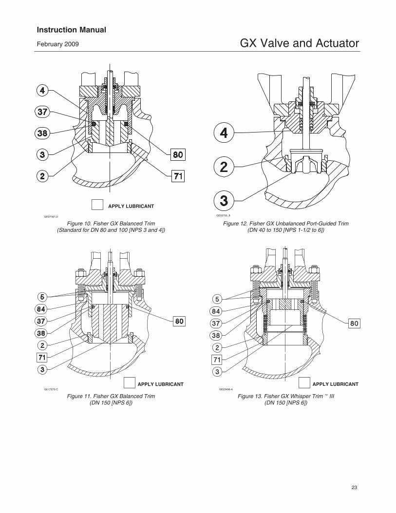
Refer to figure 10.
CAUTION
To protect the valve plug seal ring (key37) and to ensure it seals properly, becareful not to scratch the surfaces of thering groove in the valve plug or any ofthe surfaces of the replacement ring.
1. With the valve plug (key 3) removed according tothe Disassembly portion of the Valve TrimMaintenance procedure, proceed as appropriate:
The seal ring (key 37) cannot be reused because itis a closed ring which must be pried and/or cut fromthe groove. Once the seal ring is removed, theelastomeric backup ring (key 38), which is also aclosed ring, can be pried from the groove.
To install a new backup ring and seal ring onto thevalve plug, apply a general purpose silicone-baselubricant to both rings (keys 38 and 37). Place thebackup ring over the valve plug (key 3) and into thegroove. Place the seal ring over the top edge of thevalve plug (key 3) so that it enters the groove on oneside of the valve plug. Slowly and gently stretch theseal ring and work it over the top edge of the valveplug. The PTFE material in the seal ring must bepermitted time to cold-flow during the stretchingprocedure, so avoid jerking sharply on this ring.Stretching the seal ring over the valve plug maymake it seem unduly loose when in the groove, but itwill contract to its original size after insertion into thebonnet.
2. Install the seat ring, valve plug/stem, bonnet andactuator yoke into the valve body by completing theassembly according to steps 1 to 3 of the sectionAssembly of Unbalanced Trim.
Repair NameplateIf required by the end-user, an optional repairnameplate is available for recording changes madeto the valve trim during maintenance (see figure 28).This nameplate can be ordered as a spare part, andis easily mounted to the actuator casing using acasing bolt. (Reference the Parts Ordering section ofthis manual.)
As shown in figure 28, the repair nameplate provideslocations for maintenance personnel to record trimdata, such as:
� Date of maintenance
� Trim material
� Port diameter
� Flow capacity (Cv / Kv)
� Flow characteristic
� Actuator Action ATO/ATC
Bellows MaintenanceThis section provides instruction on the replacementof the bellows / stem assembly (see key 49 in figure 23).
1. Remove the actuator, bonnet assembly asdescribed in the Replacing Packing section (steps 1through 10).
2. Remove the plug/stem assemblies as describedin the Valve Trim Disassembly section (steps 2through 6).
3. To install the new bellows / stem assembly (key 49), perform the Valve Trim Assembly (step 3).
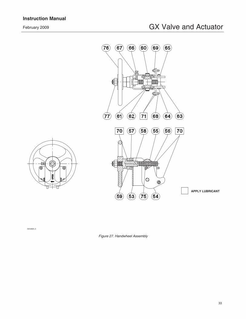
Figure 7. Fisher GX Handwheel Orientation and Grease Zerk Location
GX Valve and ActuatorInstruction Manual
February 2009
20
Handwheel Operation
CAUTION
This handwheel is designed only foruse with size 225 and 750 actuatorswith 20 mm travel. To avoid equipmentdamage, do not assemble this travelstop on size 750 actuators with 40 mmtravel or size 1200 actuators.
Principle of Operation
The GX handwheel is designed to compress theactuator springs and override the actuator fail action.Turning the handwheel drives the screw, nut, andlevers. The levers push against the stem connectorto transfer this motion. Reversing the direction of thehandwheel will move the nut and levers in theopposite direction. Once the levers are no longer incontact with the stem connector, the locking screwshould be used to secure the handwheel againstundesired movement. To prevent damage due toovertravel, the handwheel should not be turned morethan 2 full turns past the point at which the levers nolonger contact the stem connector.
WARNING
To avoid personal injury or loss ofprocess control due to equipmentdamage, ensure the levers arecompletely disengaged and thelocking screw is tight while the valve isin normal pneumatic operation.
During normal pneumatic operation when thehandwheel is not needed, a locking screw (seefigure 6) is provided on the side of the handwheelhousing to lock the handwheel levers out of the way.
WARNING
To avoid personal injury or equipmentdamage due to possible suddenshifting or falling of the valveassembly, do not lift the valveassembly by the handwheel.
GX Handwheel Installation (for use with 20mm travel only)1. Note the orientation of the levers to the stemconnector for either the air-to-close, spring-to-openconfiguration or for the air-to-open, spring-to-closeconfiguration, as shown in figure 7.
2. Adjust the handwheel to allow positioning thelevers above the stem connector before installation.
3. Install the handwheel to the GX mounting padwith four studs and nuts, as shown in figure 6.Torque to 24 N�m (18 lbf�ft).
4. Apply lithium grease to the grease zerk and to thetip of the levers (where they contact the stemconnector), as shown in figure 7.
Travel Stop Operation
Principle of Operation
CAUTION
This travel stop is designed only foruse with size 225 and 750 actuatorswith 20 mm travel. To avoid equipmentdamage, do not assemble this travelstop on size 750 actuators with 40 mmtravel or size 1200 actuators.
The GX travel stop is designed to mechanically limitand stop the valve at a preset position in anemergency or upon loss of instrument air. Thisassembly is mounted on the yoke with four studs.The lever pushes against the stem connector to stopthe travel. Travel position can be adjusted by twoadjustable cap screws on the lever, as shown infigure 8. A cover plate assembly is available toprevent pinch point damage caused by the lever, asshown in figure 8.
WARNING
To avoid personal injury or equipmentdamage due to possible suddenshifting or falling of the valveassembly, do not lift the valveassembly by the travel stop.
To avoid personal injury or loss ofprocess control due to equipmentdamage, screw the adjustable capscrews to ensure the lever iscompletely disengaged while the valveis in normal pneumatic operation.
GX Valve and ActuatorInstruction Manual
February 2009
21
COVER PLATE COVER PLATE
CAP SCREW(4)
CAP SCREW(4)
LEVER
LEVER
ADJUSTABLECAP SCREW (2)
ADJUSTABLECAP SCREW (2)
STUD ANDNUT (4)
STUD ANDNUT (4)
DOWNSTOP UPSTOP
Figure 8. Fisher GX Travel Stop Assembly
GX Travel Stop Installation
Downstop1. Note the orientation of the lever to the stemconnector for downstop positioning, as shown infigure 9. Adjust the travel stop to allow positioningthe lever below the stem connector beforeinstallation.
2. Install the travel stop to the GX mounting padwith four studs and nuts, as shown in figure 8.Torque to 24.5 N�m (18 lbf�ft).
3. Apply lithium grease to the tip of the lever (whereit contacts the stem connector) and to the twoadjustable cap screws, as shown in figure 9.
Upstop
1. Note the orientation of the lever to the stemconnector for upstop positioning, as shown in figure 9. Adjust the travel stop to allow positioningthe lever above the stem connector beforeinstallation.
2. Install the travel stop to the GX mounting padwith four studs and nuts, as shown in figure 8.Torque to 24.5 N�m (18 lbf�ft).
3. Apply lithium grease to the tip of the lever (whereit contacts the stem connector) and to the twoadjustable cap screws, as shown in figure 9.
Setting the Travel Stop PositionAfter sending the required position air signal to theactuator, screw the adjustable cap screws to assurethe lever contacts with the stem connector tightly,then tighten the back nut. Check the actual stemposition when giving the 100% air signal.
Standard Accuracy for the travel stop position is +/� 10% for 20 mm travel. For added precision, usethe following procedure.
1. Send the desired position air signal to theactuator.
2. Set the travel stop, screw the adjustable capscrews to assure the lever contacts with the stemconnector tightly, then tighten the back nut.
3. Send a 100% air signal.
4. Measure the difference between the actual stemposition and the desired position.
5. Send the air signal for the desired position minusthe differential position measured in step 4.
6. Reset the travel stop by adjusting the two capscrews and then tighten the back nut.
GX Valve and ActuatorInstruction Manual
February 2009
23
GE07161-D
APPLY LUBRICANT
Figure 10. Fisher GX Balanced Trim(Standard for DN 80 and 100 [NPS 3 and 4])
Figure 28. Repair Nameplate (Spaces Provided for Recording Trim Maintenance Data)
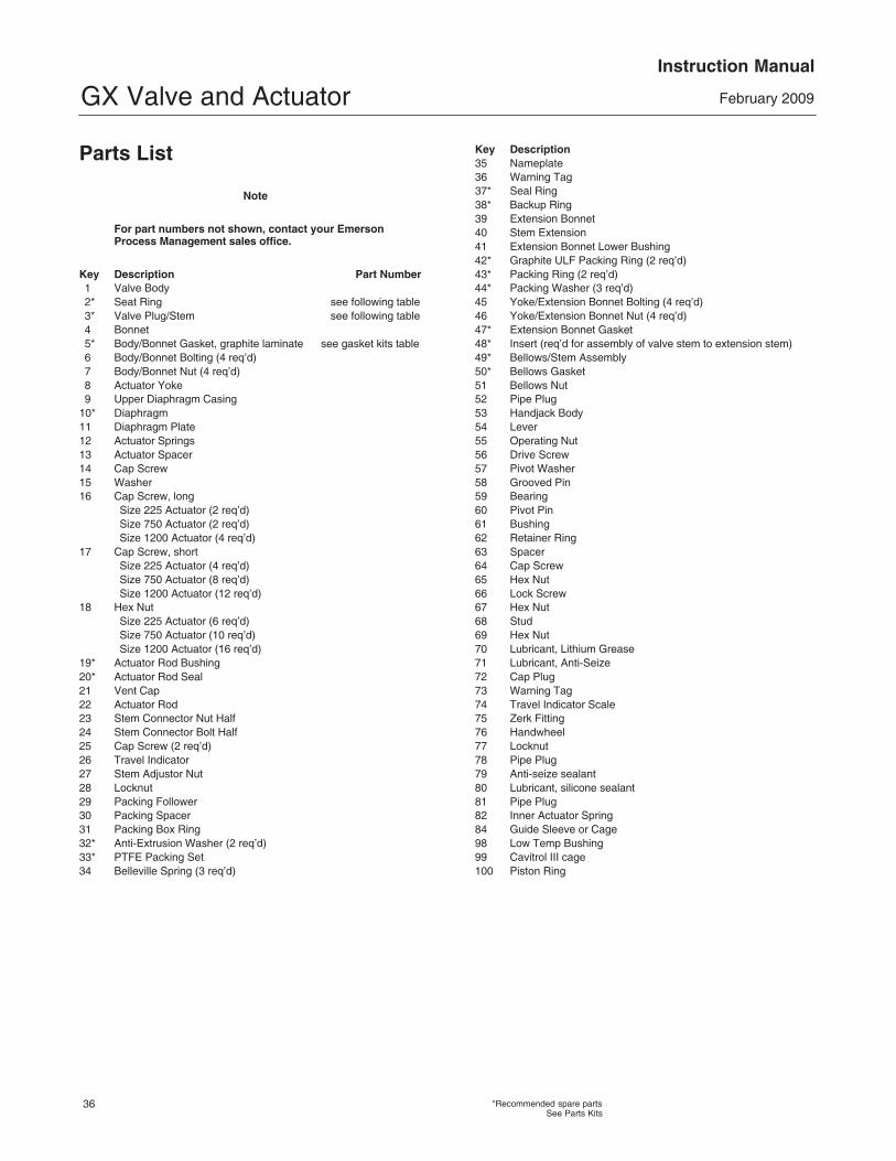
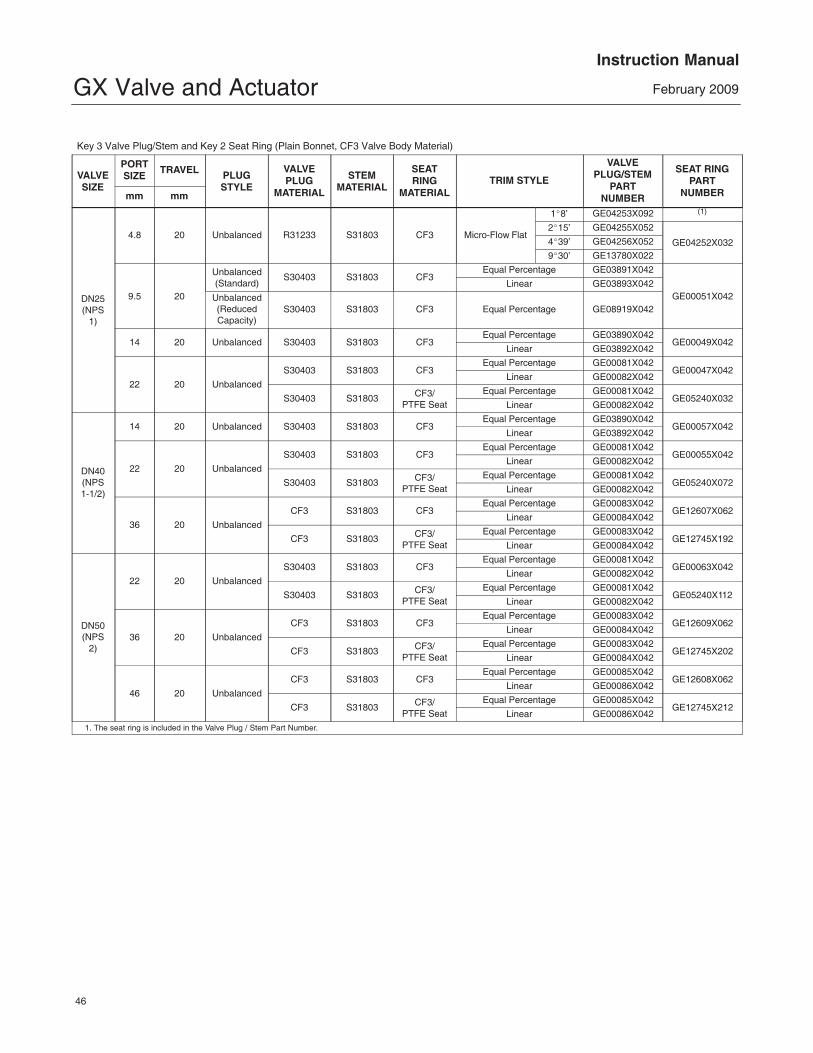
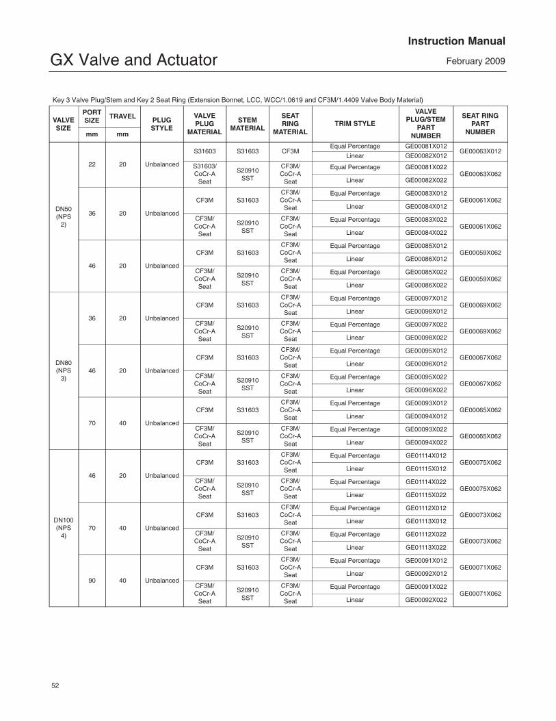
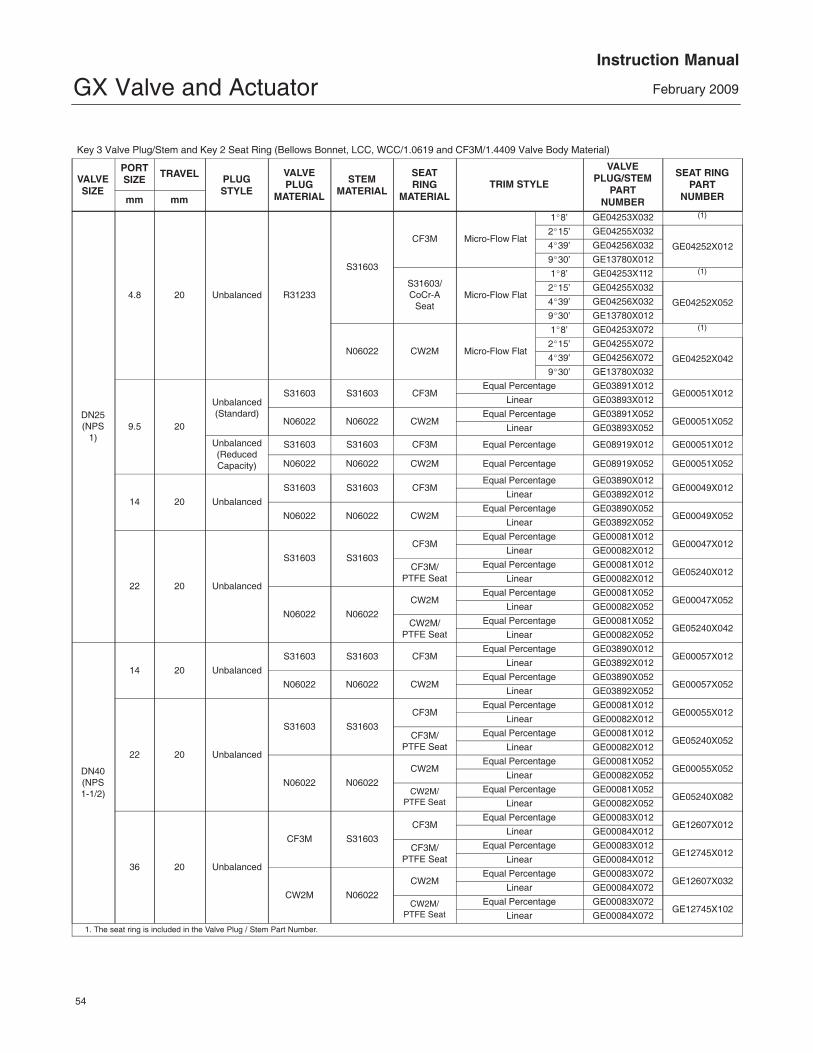
Parts OrderingEach valve is assigned a serial number which canbe found on the valve or on the nameplate (figure 2and key 35, not shown). The nameplate will normallybe fitted to the actuator. Refer to this serial numberwhen contacting your Emerson ProcessManagement sales office for technical assistance.When ordering replacement parts refer to this serialnumber and give the part description from thefollowing parts list.
WARNING
Use only genuine Fisher replacementparts. Components that are not
supplied by Emerson ProcessManagement should not, under anycircumstances, be used in any Fishervalve, because they may void yourwarranty, might adversely affect theperformance of the valve, and couldcause personal injury and propertydamage.
Note
Neither Emerson, Emerson ProcessManagement, nor any of their affiliatedentities assumes responsibility for theselection, use, or maintenance of anyproduct. Responsibility for theselection, use, and maintenance of anyproduct remains with the purchaserand end-user.
GX Valve and ActuatorInstruction Manual
February 2009
35
Parts Kits
PACKINGKITS
Valve Size
Stem Diameter
DN 25, 40, and 50(NPS 1, 1-1/2, and 2)
10 mm
DN 80 and 100 (NPS 3 and 4)
14 mm
DN 150(NPS 6)19 mm
PTFE packing (Contains keys 32 and 33) RGXPACKX012 RGXPACKX022 RGXPACKX072
Emerson Process Management Marshalltown, Iowa 50158 USASorocaba, 18087 BrazilChatham, Kent ME4 4QZ UKDubai, United Arab EmiratesSingapore 128461 Singaporewww.Fisher.com
The contents of this publication are presented for informational purposes only, and while every effort has been made to ensure their accuracy, theyare not to be construed as warranties or guarantees, express or implied, regarding the products or services described herein or their use orapplicability. All sales are governed by our terms and conditions, which are available upon request. We reserve the right to modify or improve thedesigns or specifications of such products at any time without notice. Neither Emerson, Emerson Process Management, nor any of their affiliatedentities assumes responsibility for the selection, use or maintenance of any product. Responsibility for proper selection, use, and maintenance ofany product remains solely with the purchaser and end-user.
�Fisher Controls International LLC 2003, 2009; All Rights Reserved
Fisher, FIELDVUE, Cavitrol, and Whisper Trim are marks owned by one of the companies in the Emerson Process Management business divisionof Emerson Electric Co. Emerson Process Management, Emerson, and the Emerson logo are trademarks and service marks of Emerson ElectricCo. All other marks are the property of their respective owners.