www.Fisher.com Fisher r GX Control Valve and Actuator System The Fisher GX is a compact, state-of-the-art control valve and actuator system, designed to control a wide range of process liquids, gases, and vapors. The GX is rugged, reliable, and easy to select. It requires no actuator sizing -- the actuator selection is automatic once the valve body construction is selected. The optimized design results in reduced complexity and parts count. As a result, the cost of maintenance is reduced. The GX meets the requirements of both EN and ASME standards. It is available with a complete accessory package, including the Fisher FIELDVUEt DVC2000 integrated digital valve controller. Features D Easy to size and select D No actuator sizing required--selection is automatic D Optimized actuator allows for a wide range of air supply D Engineered for easy maintenance D Maximum part commonality across sizes D Replaceable trim D Low lifetime costs D Robust, low-profile design D Compact multi-spring pneumatic actuator D Available with integrated, easy-to-calibrate DVC2000 digital valve controller W8861/IL Figure 1. Fisher GX Control Valve, Actuator, and DVC2000 Digital Valve Controller D Valve body sizes DN 15 to DN 150 (NPS 1/2 through 6) D Pressure Classes PN 10-40, CL150 and 300 D High capacity design D Valve body flow passage optimized for flow stability D Full range of materials, including alloys D Shutoff capabilities: Class IV, V, and VI D Rangeability of 50:1 (equal percentage) D Optional metal bellows seal Product Bulletin 51.1:GX D103171X012 July 2010 GX Control Valve and Actuator
Transcript
www.Fisher.com
Fisher� GX Control Valve and Actuator SystemThe Fisher GX is a compact, state-of-the-art controlvalve and actuator system, designed to control awide range of process liquids, gases, and vapors.
The GX is rugged, reliable, and easy to select. Itrequires no actuator sizing -- the actuator selection isautomatic once the valve body construction isselected.
The optimized design results in reduced complexityand parts count. As a result, the cost of maintenanceis reduced.
The GX meets the requirements of both EN andASME standards. It is available with a completeaccessory package, including the FisherFIELDVUE� DVC2000 integrated digital valvecontroller.
Features
� Easy to size and select
� No actuator sizing required--selection is automatic
� Optimized actuator allows for a wide range of air supply
� Engineered for easy maintenance
� Maximum part commonality across sizes
� Replaceable trim
� Low lifetime costs
� Robust, low-profile design
� Compact multi-spring pneumatic actuator
� Available with integrated, easy-to-calibrate DVC2000 digital valve controller
W8861/IL
Figure 1. Fisher GX Control Valve, Actuator, and DVC2000 Digital Valve Controller
� Valve body sizes DN 15 to DN 150 (NPS 1/2 through 6)
� Pressure Classes PN 10-40, CL150 and 300
� High capacity design
� Valve body flow passage optimized for flow stability
� Full range of materials, including alloys
� Shutoff capabilities: Class IV, V, and VI
� Rangeability of 50:1 (equal percentage)
� Optional metal bellows seal
Product Bulletin51.1:GXD103171X012July 2010 GX Control Valve and Actuator
GX Control Valve and ActuatorProduct Bulletin
51.1:GXJuly 2010
2
W8568-1A
COMPACT FIELD-REVERSIBLEMULTI-SPRING ACTUATOR
INTEGRATED POSITIONERMOUNTING
NAMUR POSITIONERMOUNTING CAPABILITY
ONE-PIECE SCREWEDPACKING FOLLOWER
CLAMPED BONNET DESIGN
STANDARD LIVE-LOADED PACKING
INTEGRAL PNEUMATICPASSAGEWAYS
Figure 2. Fisher GX Control Valve Assembly with Port-Guided Contoured Plug (Port Sizes 36 to 136 mm)
Optimized valve and actuator system. Productsimplicity and ease of selection form the foundationof the GX. Mounted with a digital or analog
positioner, the GX provides high performance controlacross a wide range of process applications.
Compact actuator design. The GX utilizes acompact, multi-spring actuator. The GX design hasbeen optimized to eliminate complicated actuatorsizing procedures - once the valve body, port size,and air supply pressure are selected, the actuatorsize is fixed.
Modular design. The design architecture has beenoptimized to maximize the use of common partsacross sizes. The actuator stem and stem connectorare used across all GX sizes. The GX actuator usesa total of 5 different springs across all valve sizes.These spring sets have been optimized to allow formaximum application coverage. The plug/stemassemblies and packing sets are common acrossseveral sizes, as well.
Low lifetime costs. Reduced product complexity,low parts count, and part commonality all contributeto reduced inventory and maintenance costs.
GX Control Valve and ActuatorProduct Bulletin51.1:GXJuly 2010
3
LINKAGE-LESSPOSITIONFEEDBACK
PUSH-BUTTONINSTRUMENTSETUP
W8588/IL
DVC2000COVER
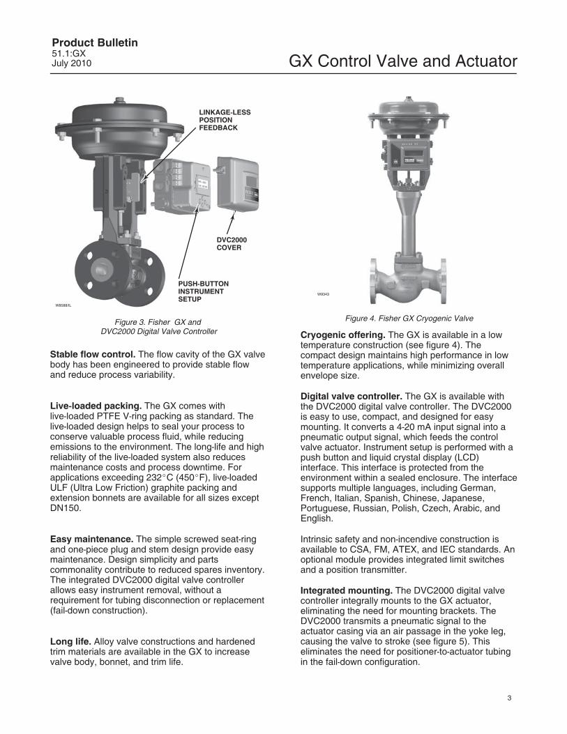
Figure 3. Fisher GX and DVC2000 Digital Valve Controller
Stable flow control. The flow cavity of the GX valvebody has been engineered to provide stable flowand reduce process variability.
Live-loaded packing. The GX comes withlive-loaded PTFE V-ring packing as standard. Thelive-loaded design helps to seal your process toconserve valuable process fluid, while reducingemissions to the environment. The long-life and highreliability of the live-loaded system also reducesmaintenance costs and process downtime. Forapplications exceeding 232�C (450�F), live-loadedULF (Ultra Low Friction) graphite packing andextension bonnets are available for all sizes exceptDN150.
Easy maintenance. The simple screwed seat-ringand one-piece plug and stem design provide easymaintenance. Design simplicity and partscommonality contribute to reduced spares inventory.The integrated DVC2000 digital valve controllerallows easy instrument removal, without arequirement for tubing disconnection or replacement(fail-down construction).
Long life. Alloy valve constructions and hardenedtrim materials are available in the GX to increasevalve body, bonnet, and trim life.
W9343
Figure 4. Fisher GX Cryogenic Valve
Cryogenic offering. The GX is available in a lowtemperature construction (see figure 4). Thecompact design maintains high performance in lowtemperature applications, while minimizing overallenvelope size.
Digital valve controller. The GX is available withthe DVC2000 digital valve controller. The DVC2000is easy to use, compact, and designed for easymounting. It converts a 4-20 mA input signal into apneumatic output signal, which feeds the controlvalve actuator. Instrument setup is performed with apush button and liquid crystal display (LCD)interface. This interface is protected from theenvironment within a sealed enclosure. The interfacesupports multiple languages, including German,French, Italian, Spanish, Chinese, Japanese,Portuguese, Russian, Polish, Czech, Arabic, andEnglish.
Intrinsic safety and non-incendive construction isavailable to CSA, FM, ATEX, and IEC standards. Anoptional module provides integrated limit switchesand a position transmitter.
Integrated mounting. The DVC2000 digital valvecontroller integrally mounts to the GX actuator,eliminating the need for mounting brackets. TheDVC2000 transmits a pneumatic signal to theactuator casing via an air passage in the yoke leg,causing the valve to stroke (see figure 5). Thiseliminates the need for positioner-to-actuator tubingin the fail-down configuration.
GX Control Valve and ActuatorProduct Bulletin
51.1:GXJuly 2010
4
FAIL-DOWN FAIL-UP
E0896-2/IL
AIR SUPPLY
AIR SUPPLY
AIR VENT
AIR VENT
Figure 5. Fisher GX Principle of Operation -- Actuator Air Supply
The DVC2000 mounting interface is identical on bothsides of the actuator yoke for valve body sizes DN15 through DN 100 (NPS 1/2 through 4). Thissymmetrical design allows the DVC2000 to be easilymoved from one side of the valve to the otherwithout the need to rotate the actuator. The DN 150(NPS 6) yoke is not symmetrical.
Linkage-less feedback. The DVC2000 digital valvecontroller offers as standard a non-contacting valveposition feedback system. This is a true linkage-lessdesign, which uses no levers and no touching partsbetween the valve stem and the positioner.
Additional Accessory selection. The GX isavailable with a variety of digital or analog
positioners besides the DVC2000, as well assolenoid and limit switches. The actuator is alsocompatible with the IEC 60534-6-1 (NAMUR)positioner mounting standard.
Principle of OperationIntegrated Air Supply. When mounted with theDVC2000 digital valve controller, the GX uses anintegrated actuator air supply system. In thefail-down construction, air is supplied to the loweractuator casing via a port on the actuator yoke face-- no tubing is required. In the fail-up configuration,air is supplied to the upper casing via tubing.
GX Control Valve and ActuatorProduct Bulletin51.1:GXJuly 2010
5
PLUG
SCREWED-INSEAT RING
PTFE SEAT
W9023-1
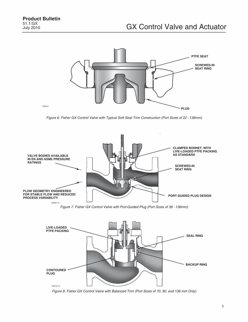
Figure 6. Fisher GX Control Valve with Typical Soft Seat Trim Construction (Port Sizes of 22 - 136mm)
W8568-1/IL
CLAMPED BONNET, WITHLIVE-LOADED PTFE PACKINGAS STANDARD
PORT-GUIDED PLUG DESIGN
VALVE BODIES AVAILABLEIN EN AND ASME PRESSURERATINGS
FLOW GEOMETRY ENGINEEREDFOR STABLE FLOW AND REDUCEDPROCESS VARIABILITY
SCREWED-INSEAT RING
Figure 7. Fisher GX Control Valve with Port-Guided Plug (Port Sizes of 36 - 136mm)
CONTOUREDPLUG
SEAL RING
BACKUP RING
LIVE-LOADEDPTFE PACKING
W8578-1/IL
Figure 8. Fisher GX Control Valve with Balanced Trim (Port Sizes of 70, 90, and 136 mm Only)
GX Control Valve and ActuatorProduct Bulletin
51.1:GXJuly 2010
6
W8486-3/IL
COMPACT FIELD-REVERSIBLEMULTI-SPRING ACTUATOR
INTEGRATED POSITIONERMOUNTING
NAMUR POSITIONERMOUNTING CAPABILITY
ONE-PIECE SCREWEDPACKING FOLLOWER
CLAMPED BONNET DESIGN
STANDARD LIVE-LOADED PACKING
INTEGRAL PNEUMATICPASSAGEWAYS
Figure 9. Fisher GX Control Valve Assembly with Stem-Guided Contoured Plug (Size DN 25/1-Inch)
The Fisher GX Control ValveThe GX is a single port, flow-up globe style valvethat offers port-guided (figure 2), stem-guided (figure 9), and balanced trim with a screwed-in seatring (see table 1 for a description of trim styleavailability). Each valve size offers an unbalancedplug design, which eliminates dead spaces wherefluid polymerization might occur. Although theoptimized GX actuator allows for wide usage ofunbalanced trim, a balanced plug design is availablefor higher pressure drop applications in DN80, 100and 150 (NPS 3, 4, and 6) sizes.
The GX incorporates a clamped bonnet and aneasy-to-adjust screwed packing follower (see figure 2). The plug and stem are a rugged, one-piecewelded assembly.
The standard construction incorporatesmetal-to-metal seating, with a PTFE soft seat option
for Class VI shutoff (see figure 6). Class V shutoff isavailable with metal trim. Hardened trim with stelliteoverlay is available for erosive service, as well.
PTFE V-ring stem packing is standard with the GX.The live-loaded system provides excellent stemsealing and extended service life. Live-loadedgraphite ULF packing and extension bonnets areavailable for high temperature applications.
Both linear and equal percentage flowcharacteristics are available in full port and restrictedtrim. Micro-Flow is available for applicationsrequiring low flow control capability.
Standard valve body materials are carbon steel andstainless steel. Alloy materials are available for valvebody sizes DN 15 through DN 100 (NPS 1/2 through 4) for highly corrosive applications.
GX Control Valve and ActuatorProduct Bulletin51.1:GXJuly 2010
7
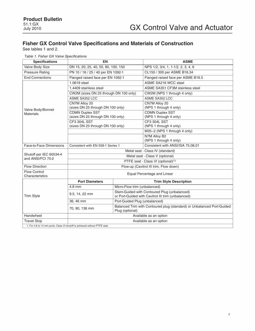
Fisher GX Control Valve Specifications and Materials of ConstructionSee tables 1 and 2.
CW2M (sizes DN 25 through DN 100 only) CW2M (NPS 1 through 4 only)ASME SA352 LCC ASME SA352 LCC
CN7M Alloy 20 (sizes DN 25 through DN 100 only)
CN7M Alloy 20 (NPS 1 through 4 only)
CDMN Duplex SST (sizes DN 25 through DN 100 only)
CDMN Duplex SST (NPS 1 through 4 only)
CF3 304L SST (sizes DN 25 through DN 100 only)
CF3 304L SST (NPS 1 through 4 only)M35�2 (NPS 1 through 4 only)
N7M Alloy B2 (NPS 1 through 4 only)
Face-to-Face Dimensions Consistent with EN 558-1 Series 1 Consistent with ANSI/ISA 75.08.01
Shutoff per IEC 60534-4 and ANSI/FCI 70-2
Metal seat - Class IV (standard)
Metal seat - Class V (optional)
PTFE seat - Class VI (optional)(1)
Flow Direction Flow-up (Cavitrol III trim, Flow down)
Flow ControlCharacteristics
Equal Percentage and Linear
Trim Style
Port Diameters Trim Style Description4.8 mm Micro-Flow trim (unbalanced)
9.5, 14, 22 mm Stem-Guided with Contoured Plug (unbalanced)or Port-Guided with Cavitrol III trim (unbalanced)
36, 46 mm Port-Guided Plug (unbalanced)
70, 90, 136 mm Balanced Trim with Contoured plug (standard) or Unbalanced Port-GuidedPlug (optional)
Handwheel Available as an option
Travel Stop Available as an option1. For 4.8 to 14 mm ports, Class VI shutoff is achieved without PTFE seat.
GX Control Valve and ActuatorProduct Bulletin
51.1:GXJuly 2010
8
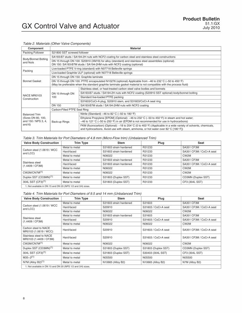
Table 2. Materials (Other Valve Components)Component Material
Packing Follower S21800 SST screwed follower
Body/Bonnet Boltingand Nuts
SA193-B7 studs / SA194-2H nuts with NCF2 coating for carbon steel and stainless steel constructions
DN 15 through DN 100: S20910 (XM19) for alloy (standard) and stainless steel assemblies (optional)DN 150: SA193-B7M studs / SA194-2HM nuts with NCF2 coating (optional)
PackingLive-loaded PTFE V-ring (standard) with N07718 Belleville springs
Live-loaded Graphite ULF (optional) with N07718 Belleville springs
Bonnet Gasket
DN 15 through DN 150: Graphite laminate
DN 15 through DN 100: PTFE encapsulated N10276 (optional) Applicable from �46 to 232�C (�50 to 450�F)(May be preferable when the standard graphite laminate gasket material is not compatible with the process fluid)
NACE MR0103Construction
DN 15 through DN100
Stainless steel, or heat-treated carbon steel valve bodies and bonnets
Ethylene Propylene [EPDM] (Optional): �46 to 232�C (�50 to 450�F) in steam and hot water; �46 to 121�C (�50 to 250�F) in air (EPDM is not recommended for use in hydrocarbons)
FKM (fluorocarbon) (Optional): �18 to 204�C (0 to 400�F) (Applicable in a wide variety of solvents, chemicals,and hydrocarbons. Avoid use with steam, ammonia, or hot water over 82�C [180�F])
Table 3. Trim Materials for Port Diameters of 4.8 mm (Micro-Flow trim) (Unbalanced Trim)Valve Body Construction Trim Type Stem Plug Seat
Carbon steel (1.0619 / WCCand LCC)
Metal to metal S31603 strain hardened R31233 SA351 CF3M
N7M (Alloy B2)(1) Metal to metal N10665 (Alloy B2)N10665 (22 mm)/ N7M (>22 mm)
N7M (Alloy B2)
1. Not available for DN 150 (NPS 6).2. Whisper Trim III is only available in 70 and 90 mm ports.3. DN150 (NPS 6) has CoCr�A seat and guide.4. DN150 (NPS 6) has CoCr�A guide.
Table 6. Trim Materials for Port Diameters of 70, 90, and 136 mm (Balanced Trim)(3)
Valve Body Construction Trim Type Stem Plug Seat
Carbon steel (1.0619 / WCC and LCC)(1)
Metal to metal S31603 strain hardened S31603 SA351 CF3M
Hard-faced/Whisper Trim III(4) S20910
S31603 / CoCr�A seat andguide
SA351 CF3M / CoCr-A seatand guide
Metal to metal N06022 N06022 CW2M(2)
Stainless steel (1.4409 / CF3M)
Metal to metal S31603 strain hardened S31603 SA351 CF3M
Hard-faced/Whisper Trim III(4) S20910S31603 / CoCr�A seat andguide
CW2M(2) / CN7M(2) Metal to metal N06022 N06022 CW2M
Duplex SST (CD3MN)(2) Metal to metal S31803 (Duplex SST) S31803 (Duplex SST) CD3MN (Duplex SST)
304L SST (CF3)(2) Metal to metal S31803 (Duplex SST) S30403 (304L SST) CF3 (304L SST)
1. The bonnet used in the carbon steel balanced trim construction is made of 1.4409/CF3M stainless steel.2. Not available for DN 150 (NPS 6).3. Balanced trim not available with M35�2 or N7M trim.4. Balanced Whisper Trim III in DN150 (NPS 6) 136 mm port diameter only.
GX Control Valve and ActuatorProduct Bulletin
51.1:GXJuly 2010
10
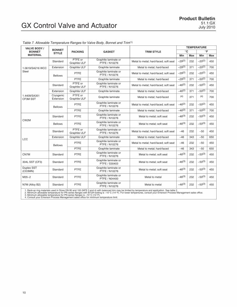
Table 7. Allowable Temperature Ranges for Valve Body, Bonnet and Trim(1)
1. Back-up ring materials used in Sizes DN 80 and 100 (NPS 3 and 4) with balanced trim may be limited by temperature and application. See table 2.2. Minimum allowable temperature for PN series flanges with B7/2H bolting is �10�C (14�F). For lower tempertures, consult your Emerson Process Management sales office.3. Minimum allowable temperature for PN series flanges is �10�C (14�F).4. Consult your Emerson Process Management sales office for minimum temperature limit.
GX Control Valve and ActuatorProduct Bulletin51.1:GXJuly 2010
11
E1026
E1140
Figure 10. Material Pressure/Temperature Curves
GX Control Valve and ActuatorProduct Bulletin
51.1:GXJuly 2010
12
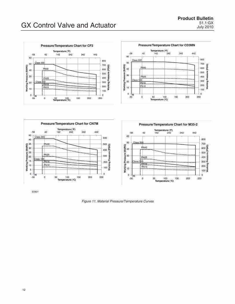
E0901
Figure 11. Material Pressure/Temperature Curves
GX Control Valve and ActuatorProduct Bulletin51.1:GXJuly 2010
13
BELLEVILLESPRING PACK
PACKING SPACER
PACKING SETANTI-EXTRUSIONWASHER
PACKINGBOX RING
ANTI-EXTRUSIONWASHER
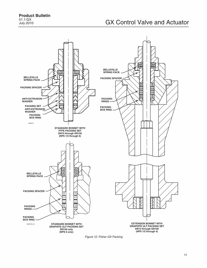
STANDARD BONNET WITHPTFE PACKING SETDN15 through DN150(NPS 1/2 through 6)
EXTENSION BONNET WITHGRAPHITE ULF PACKING SET
DN15 through DN100(NPS 1/2 through 4)
BELLEVILLESPRING PACK
PACKING SPACER
PACKINGBOX RING
PACKINGRINGS
E0897/IL
STANDARD BONNET WITHGRAPHITE ULF PACKING SET
DN150 only(NPS 6 only)
BELLEVILLESPRING PACK
PACKING SPACER
PACKINGRINGS
PACKINGBOX RING
GE03755_23
Figure 12. Fisher GX Packing
GX Control Valve and ActuatorProduct Bulletin
51.1:GXJuly 2010
14
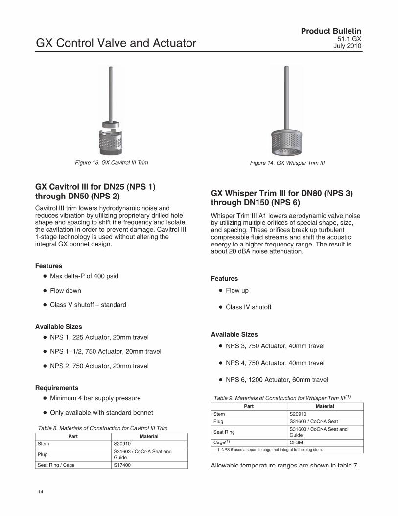
Figure 13. GX Cavitrol III Trim
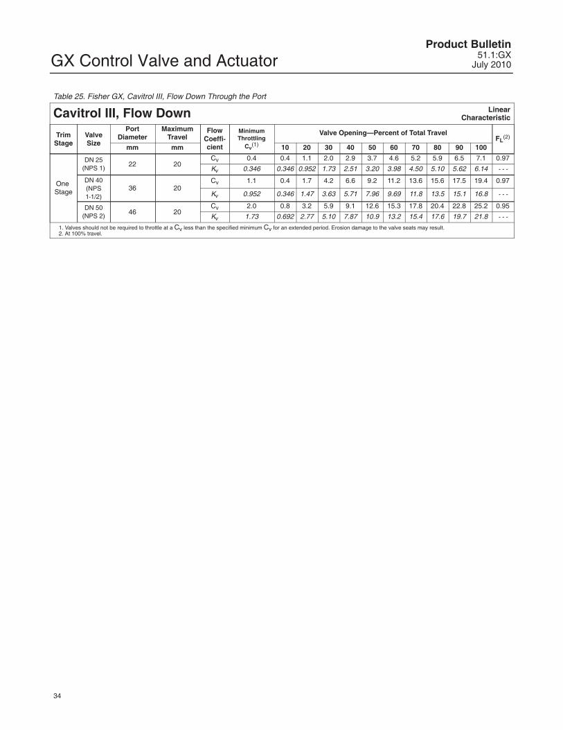
GX Cavitrol III for DN25 (NPS 1)through DN50 (NPS 2)Cavitrol III trim lowers hydrodynamic noise andreduces vibration by utilizing proprietary drilled holeshape and spacing to shift the frequency and isolatethe cavitation in order to prevent damage. Cavitrol III1-stage technology is used without altering theintegral GX bonnet design.
Features
� Max delta-P of 400 psid
� Flow down
� Class V shutoff – standard
Available Sizes
� NPS 1, 225 Actuator, 20mm travel
� NPS 1�1/2, 750 Actuator, 20mm travel
� NPS 2, 750 Actuator, 20mm travel
Requirements
� Minimum 4 bar supply pressure
� Only available with standard bonnet
Table 8. Materials of Construction for Cavitrol III TrimPart Material
Stem S20910
Plug S31603 / CoCr-A Seat andGuide
Seat Ring / Cage S17400
Figure 14. GX Whisper Trim III
GX Whisper Trim III for DN80 (NPS 3)through DN150 (NPS 6)
Whisper Trim III A1 lowers aerodynamic valve noiseby utilizing multiple orifices of special shape, size,and spacing. These orifices break up turbulentcompressible fluid streams and shift the acousticenergy to a higher frequency range. The result isabout 20 dBA noise attenuation.
Features
� Flow up
� Class IV shutoff
Available Sizes
� NPS 3, 750 Actuator, 40mm travel
� NPS 4, 750 Actuator, 40mm travel
� NPS 6, 1200 Actuator, 60mm travel
Table 9. Materials of Construction for Whisper Trim III(1)
Part Material
Stem S20910
Plug S31603 / CoCr-A Seat
Seat Ring S31603 / CoCr-A Seat andGuide
Cage(1) CF3M1. NPS 6 uses a separate cage, not integral to the plug stem.
Allowable temperature ranges are shown in table 7.
GX Control Valve and ActuatorProduct Bulletin51.1:GXJuly 2010
15
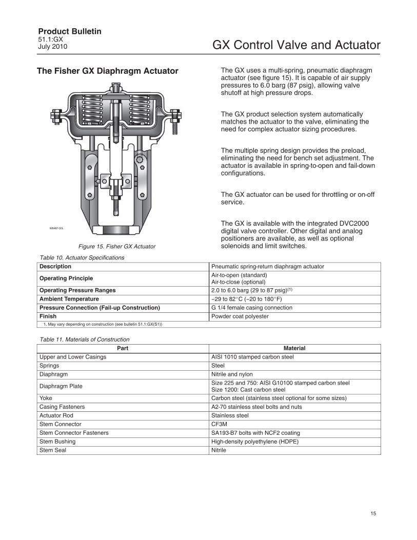
The Fisher GX Diaphragm Actuator
W8487-3/IL
Figure 15. Fisher GX Actuator
The GX uses a multi-spring, pneumatic diaphragmactuator (see figure 15). It is capable of air supplypressures to 6.0 barg (87 psig), allowing valveshutoff at high pressure drops.
The GX product selection system automaticallymatches the actuator to the valve, eliminating theneed for complex actuator sizing procedures.
The multiple spring design provides the preload,eliminating the need for bench set adjustment. Theactuator is available in spring-to-open and fail-downconfigurations.
The GX actuator can be used for throttling or on-offservice.
The GX is available with the integrated DVC2000digital valve controller. Other digital and analogpositioners are available, as well as optionalsolenoids and limit switches.
Yoke Carbon steel (stainless steel optional for some sizes)
Casing Fasteners A2-70 stainless steel bolts and nuts
Actuator Rod Stainless steel
Stem Connector CF3M
Stem Connector Fasteners SA193-B7 bolts with NCF2 coating
Stem Bushing High-density polyethylene (HDPE)
Stem Seal Nitrile
GX Control Valve and ActuatorProduct Bulletin
51.1:GXJuly 2010
16
Actuator Selection
With the GX, actuator selection has never beeneasier. Once the valve size and port diameter havebeen determined, the actuator is automaticallyselected. No spring selection or bench setcalculations are required.
The majority of GX constructions (both fail-down andfail-up) are rated to a full pressure class shutoffcapability of 51.7 bar (750 psi) for a 4 to 6 bar (58 to87 psig) actuator air supply. Refer to Fisher bulletin51.1:GX (S1) for additional information.
The GX actuator has been optimized to allow forvarying ranges of supply pressure. See table 12.
Bellows Extension BonnetThe GX bellows extension bonnet provides reliableand tight stem sealing for those applications where
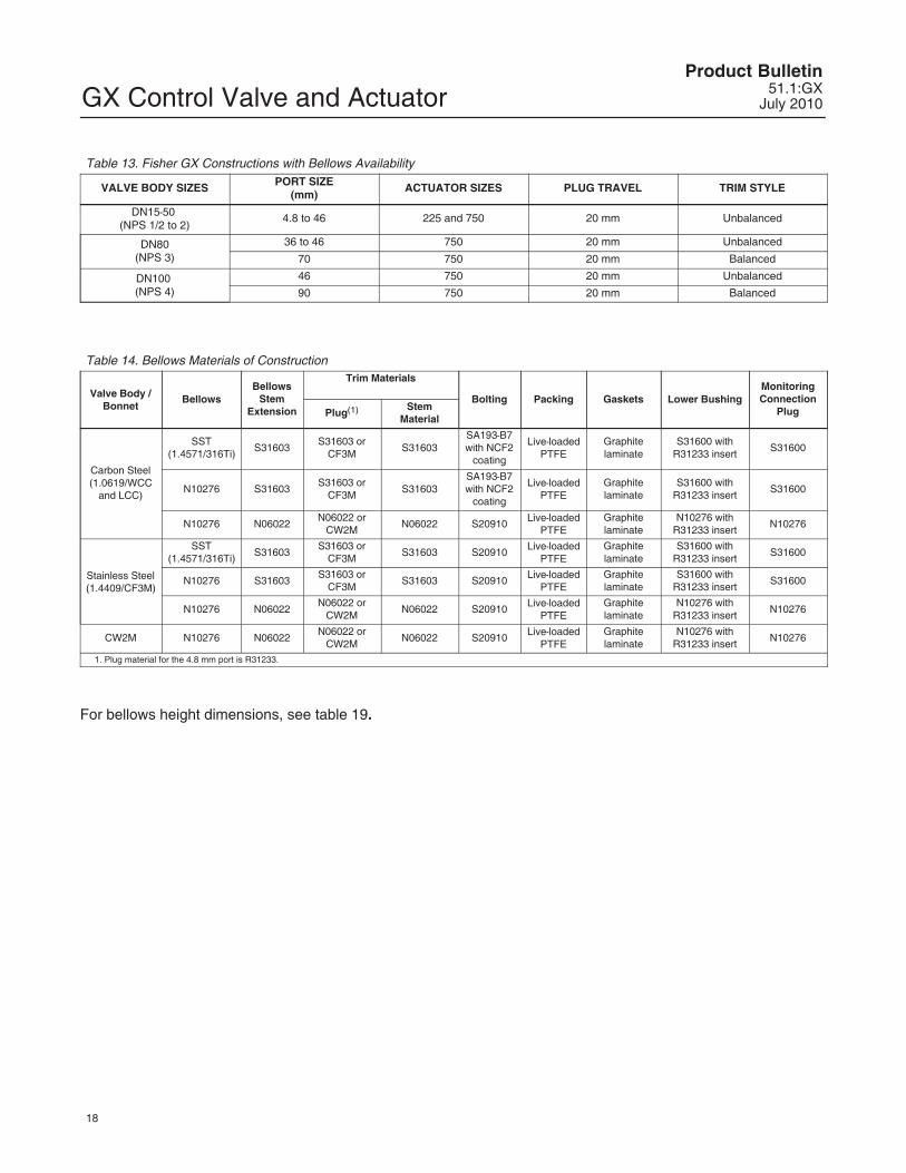
emissions escaping to the environment cannot betolerated (see figure 16). The GX bellows isavailable in SST (1.4571 / 316Ti) or N10276 andcovers a full range of valve sizes from DN 15through DN 100 (NPS 1/2 through 4) (see tables 13and 14).
The GX bellows system has been designedfor 100,000 full-travel cycles at maximumallowable pressure and ambient temperature(20�C [68�F]).
The mechanically-formed metal bellows provideshigh operating reliability and extended cycle life (seetables 15, 16, and 17 for details).
The GX bellows design incorporates a ruggeddouble- or triple-wall construction for added security.Each bellows has been tested with helium before itleaves the factory.
The GX bellows bonnet comes standard with alive-loaded, PTFE packing system as a securitybackup. A connection is provided above the bellowsto allow purging or monitoring the integrity of thereplaceable bellows.
GX Control Valve and ActuatorProduct Bulletin51.1:GXJuly 2010
17
W8958-1
PACKINGFOLLOWER
BONNET
LIVE-LOADEDPTFE PACKING
BODY/BONNETGASKET
PURGE / MONITORINGCONNECTION
BELLOWS NUT
BELLOWSGASKET
BELLOWS/STEMASSEMBLY
EXTENSIONBONNET
BUSHING
VALVE PLUG
Step 1Size and select the GX control valve that isappropriate for the application. This will identifythe:
� Valve body size� Actuator size� Orifice size�Trim style (balanced or unbalanced)� Valve body material
Step 4Using bulletin 51.1:GX(S1), verify the applicationpressure drop does not exceed the actuatorcapability.
Step 2Confirm bellows availability from table 13.
Step 3Using table 14, select the bellows materialcombination that is appropriate for theapplication. Using the temperature limits shownin table 7, confirm the selected construction isappropriate for the application temperatures.
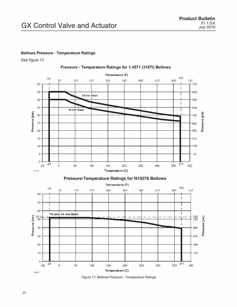
Step 5Using figure 17, check to ensure the maximumprocess pressure and temperature do not exceedthe pressure-temperature rating of the selectedbellows.
Bellows Selection ProcessFollow this process to assist in selecting
the appropriate bellows for the application.
Figure 16. Fisher GX Bellows Bonnet and Selection Process
GX Control Valve and ActuatorProduct Bulletin
51.1:GXJuly 2010
18
Table 13. Fisher GX Constructions with Bellows Availability
GX Control Valve and ActuatorProduct Bulletin51.1:GXJuly 2010
19
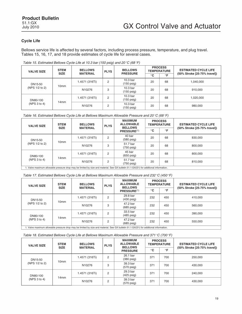
Cycle Life
Bellows service life is affected by several factors, including process pressure, temperature, and plug travel.Tables 15, 16, 17, and 18 provide estimates of cycle life for several cases.
Table 15. Estimated Bellows Cycle Life at 10.3 bar (150 psig) and 20�C (68�F)
VALVE SIZE STEMSIZE
BELLOWSMATERIAL
PLYS BELLOWSPRESSURE
PROCESSTEMPERATURE ESTIMATED CYCLE LIFE
(50% Stroke [25-75% travel])�C �F
DN15-50 (NPS 1/2 to 2) 10mm
1.4571 (316Ti) 2 10.3 bar (150 psig)
20 68 1,040,000
N10276 3 10.3 bar (150 psig)
20 68 910,000
DN80-100 (NPS 3 to 4) 14mm
1.4571 (316Ti) 2 10.3 bar (150 psig)
20 68 1,020,000
N10276 2 10.3 bar (150 psig)
20 68 980,000
Table 16. Estimated Bellows Cycle Life at Bellows Maximum Allowable Pressure and 20�C (68�F)
VALVE SIZE STEMSIZE
BELLOWSMATERIAL
PLYS
MAXIMUMALLOWABLE
BELLOWSPRESSURE(1)
PROCESSTEMPERATURE ESTIMATED CYCLE LIFE
(50% Stroke [25-75% travel])�C �F
DN15-50 (NPS 1/2 to 2) 10mm
1.4571 (316Ti) 2 40 bar (580 psig)
20 68 830,000
N10276 3 51.7 bar (750 psig)
20 68 800,000
DN80-100 (NPS 3 to 4) 14mm
1.4571 (316Ti) 2 45 bar (650 psig)
20 68 800,000
N10276 2 51.7 bar (750 psig)
20 68 810,000
1. Valve maximum allowable pressure drop may be limited by size and material. See GX bulletin 51.1:GX(S1) for additional information.
Table 17. Estimated Bellows Cycle Life at Bellows Maximum Allowable Pressure and 232�C (450�F)
VALVE SIZE STEMSIZE
BELLOWSMATERIAL
PLYS
MAXIMUMALLOWABLE
BELLOWSPRESSURE(1)
PROCESSTEMPERATURE ESTIMATED CYCLE LIFE
(50% Stroke [25-75% travel])�C �F
DN15-50 (NPS 1/2 to 2) 10mm
1.4571 (316Ti) 2 29.8 bar (430 psig)
232 450 410,000
N10276 3 47.2 bar (685 psig)
232 450 560,000
DN80-100 (NPS 3 to 4) 14mm
1.4571 (316Ti) 2 33.5 bar (485 psig)
232 450 390,000
N10276 2 47.2 bar (685 psig)
232 450 550,000
1. Valve maximum allowable pressure drop may be limited by size and material. See GX bulletin 51.1:GX(S1) for additional information.
Table 18. Estimated Bellows Cycle Life at Bellows Maximum Allowable Pressure and 371�C (700�F)
VALVE SIZE STEMSIZE
BELLOWSMATERIAL
PLYS
MAXIMUMALLOWABLE
BELLOWSPRESSURE
PROCESSTEMPERATURE ESTIMATED CYCLE LIFE
(50% Stroke [25-75% travel])�C �F
DN15-50 (NPS 1/2 to 2) 10mm
1.4571 (316Ti) 2 26.1 bar (380 psig)
371 700 250,000
N10276 3 39.3 bar (570 psig)
371 700 430,000
DN80-100 (NPS 3 to 4) 14mm
1.4571 (316Ti) 2 29.3 bar (425 psig)
371 700 240,000
N10276 2 39.3 bar (570 psig)
371 700 430,000
GX Control Valve and ActuatorProduct Bulletin
51.1:GXJuly 2010
20
Bellows Pressure - Temperature Ratings
See figure 17.
Pressure-Temperature Ratings for N10276 Bellows
Figure 17. Bellows Pressure - Temperature Ratings
GX Control Valve and ActuatorProduct Bulletin51.1:GXJuly 2010
21
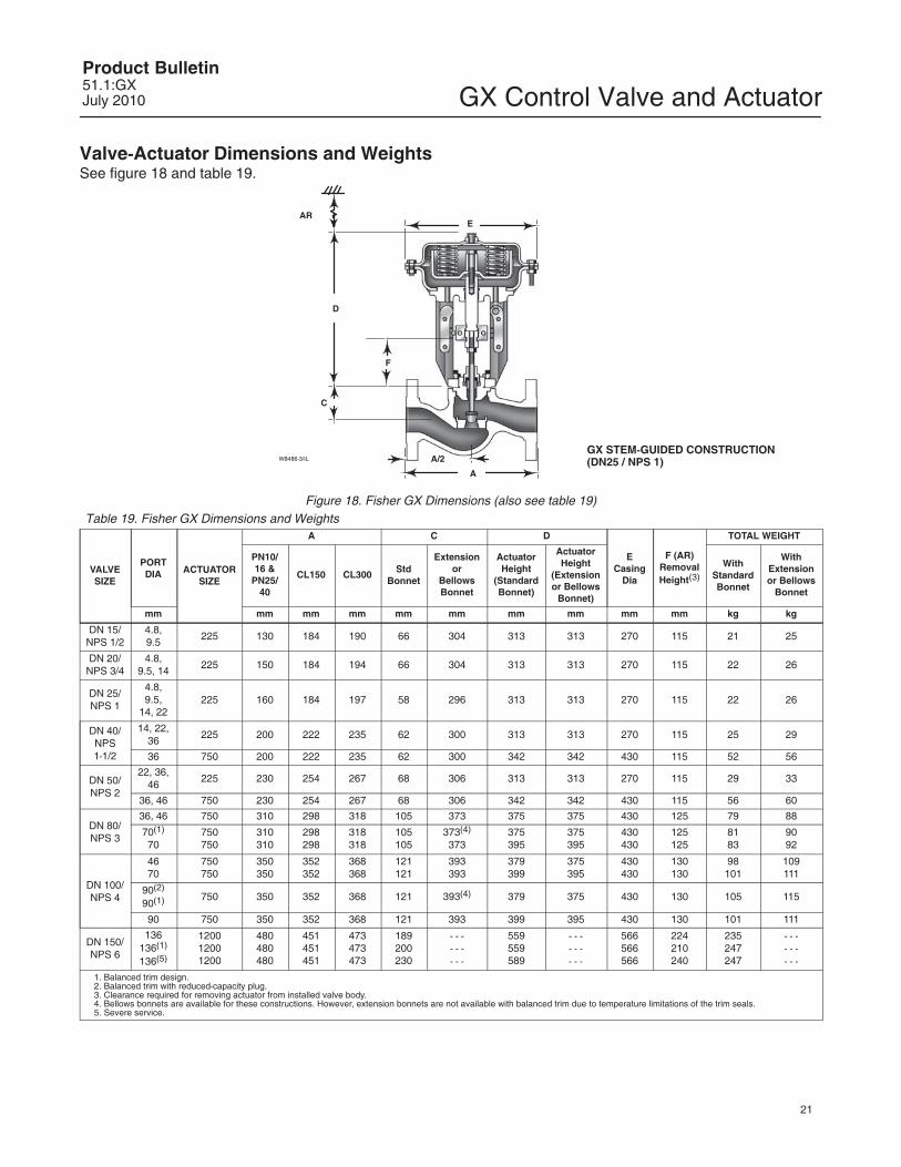
Valve-Actuator Dimensions and WeightsSee figure 18 and table 19.
1. Balanced trim design.2. Balanced trim with reduced-capacity plug.3. Clearance required for removing actuator from installed valve body.4. Bellows bonnets are available for these constructions. However, extension bonnets are not available with balanced trim due to temperature limitations of the trim seals.5. Severe service.
GX Control Valve and ActuatorProduct Bulletin
51.1:GXJuly 2010
22
Table 20. Positioner Selection Guidelines
Type Digital I/P(1) I/P(2) P/P(3) IntrinsicSafety(4)
Flameproof /Explosionproof(4) Non- Incendive(4)
DVC2000 X X XDVC6030 X X X X3661 X X X3660 X
1. Digital I/P - microprocessor based electro-pneumatic with HART communication.2. I/P - electro-pneumatic3. P/P - pneumatic4. Refer to Fisher bulletin 9.2:001 for instrument hazardous area classification details.
Fisher GX Actuator Accessories
The GX is available with a variety of pneumatic(P/P), electro-pneumatic (I/P), and digital valvepositioners, as well as limit switches and solenoids.Table 20 provides the basic features of thepositioners offered with the GX actuator.
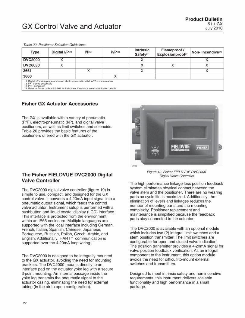
The Fisher FIELDVUE DVC2000 DigitalValve Controller
The DVC2000 digital valve controller (figure 19) issimple to use, compact, and designed for the GXcontrol valve. It converts a 4-20mA input signal into apneumatic output signal, which feeds the controlvalve actuator. Instrument setup is performed with apushbutton and liquid crystal display (LCD) interface.This interface is protected from the environmentwithin an IP66 enclosure. Multiple languages aresupported with the local interface including German,French, Italian, Spanish, Chinese, Japanese,Portuguese, Russian, Polish, Czech, Arabic, andEnglish. Additionally, HART� communication issupported over the 4-20mA loop wiring.
The DVC2000 is designed to be integrally mountedto the GX actuator, avoiding the need for mountingbrackets. The DVC2000 mounts directly to aninterface pad on the actuator yoke leg with a secure3-point mounting. An internal passage inside theyoke leg transmits the pneumatic signal to theactuator casing, eliminating the need for externaltubing (in the air-to-open configuration).
W8755
Figure 19. Fisher FIELDVUE DVC2000 Digital Valve Controller
The high-performance linkage-less position feedbacksystem eliminates physical contact between thevalve stem and the positioner. There are no wearingparts so cycle life is maximized. Additionally, theelimination of levers and linkages reduces thenumber of mounting parts and the mountingcomplexity. Positioner replacement andmaintenance is simplified because the feedbackparts stay connected to the actuator.
The DVC2000 is available with an optional modulewhich includes two (2) integral limit switches and astem position transmitter. The limit switches areconfigurable for open and closed valve indication.The position transmitter provides a 4-20mA signal forvalve position feedback verification. As an integralcomponent to the instrument, this option moduleavoids the need for difficult-to-mount externalswitches and transmitters.
Designed to meet intrinsic safety and non-incendiverequirements, this instrument delivers scalablefunctionality and high performance in a smallpackage.
GX Control Valve and ActuatorProduct Bulletin51.1:GXJuly 2010
23
Optional Positioners and Instruments
Fisher 3660 and 3661 Valve Positioners
The 3660 pneumatic and 3661 electro-pneumaticpositioners are rugged, accurate, and feature lowsteady-state air consumption. Designed to meetintrinsic safety requirements, these positioners offersimple functionality in a small package. (See figure 20 and table 20.)
Fisher FIELDVUE DVC6030 Digital ValveController
The DVC6030 digital valve controller is acommunicating, microprocessor-based positioner.Using HART or FOUNDATION� fieldbuscommunication protocol, access to criticalinstrument, valve, and process conditions isprovided. When used with ValveLink� software,valve diagnostic tests can be run while the valve is inservice to advise you of the performance of theentire control valve assembly. Designed to meet abroad range of hazardous area classifications, thispositioner offers maximum functionality to improveyour process performance. (See figure 21 and table20.)
W8590/IL
Figure 20. Fisher GX Valve with 3660 or 3661 Positioner,NAMUR Mounting (IEC 60534-6-1)
W7963-1/IL
Figure 21. Fisher FIELDVUE DVC6030 Digital Valve Controller
GX Control Valve and ActuatorProduct Bulletin
51.1:GXJuly 2010
24
Manual HandwheelsThe GX is available with an optional, side-mountedmanual handwheel (see figure 22). Thesehandwheels provide a robust method of manuallyoperating the valve in an emergency or upon loss ofinstrument air.
The GX handwheel will stroke the valve up to 20mmtravel, and is available on the size 225 and 750
actuators. Dimensions are provided in figure 23 andtable 21.
When mounted to a fail-up actuator, rotating thehandwheel clockwise moves the stem downwards.When mounted to a fail-down actuator, turning thehandwheel in the clockwise direction causes thestem to move upwards. Disengagement of thehandwheel to allow automatic operation isaccomplished by simply rewinding the handwheel.
W9025
Figure 22. Fisher GX Control Valve and Actuator System with Manual Handwheel
GX Control Valve and ActuatorProduct Bulletin51.1:GXJuly 2010
25
E0975
A1A2
A1A2
C1
C2
� B
� B
Figure 23. Fisher GX with Handwheel Dimensions (also see table 21)
Table 21. Fisher GX with Handwheel Dimensions and WeightsVALVE SIZE
ACTUATORSIZE
VALVETRAVEL
HANDWHEELWEIGHT
A1 A2 B C1(1) C2(2)
ENASME
NPS mm kg mm mm mm mm mm
DN 15 1/2 225 20 5.6 215 242 223 159 60
DN 20 3/4 225 20 5.6 215 242 223 159 60
DN 25 1 225 20 5.6 215 242 223 159 60
DN 40 1-1/2225750
2020
5.612.2
215293
242317
223356
159159
6060
DN 50 2 225750
2020
5.612.2
215293
242317
223356
159159
6060
DN 80 3 750 20 12.2 293 317 356 169 70
DN 100 4 750 20 12.2 293 317 356 173 74
DN 150 6 1200 Contact your Emerson Process Management sales office for information.1. C1 is fail-down.2. C2 is fail-up.
GX Control Valve and ActuatorProduct Bulletin
51.1:GXJuly 2010
26
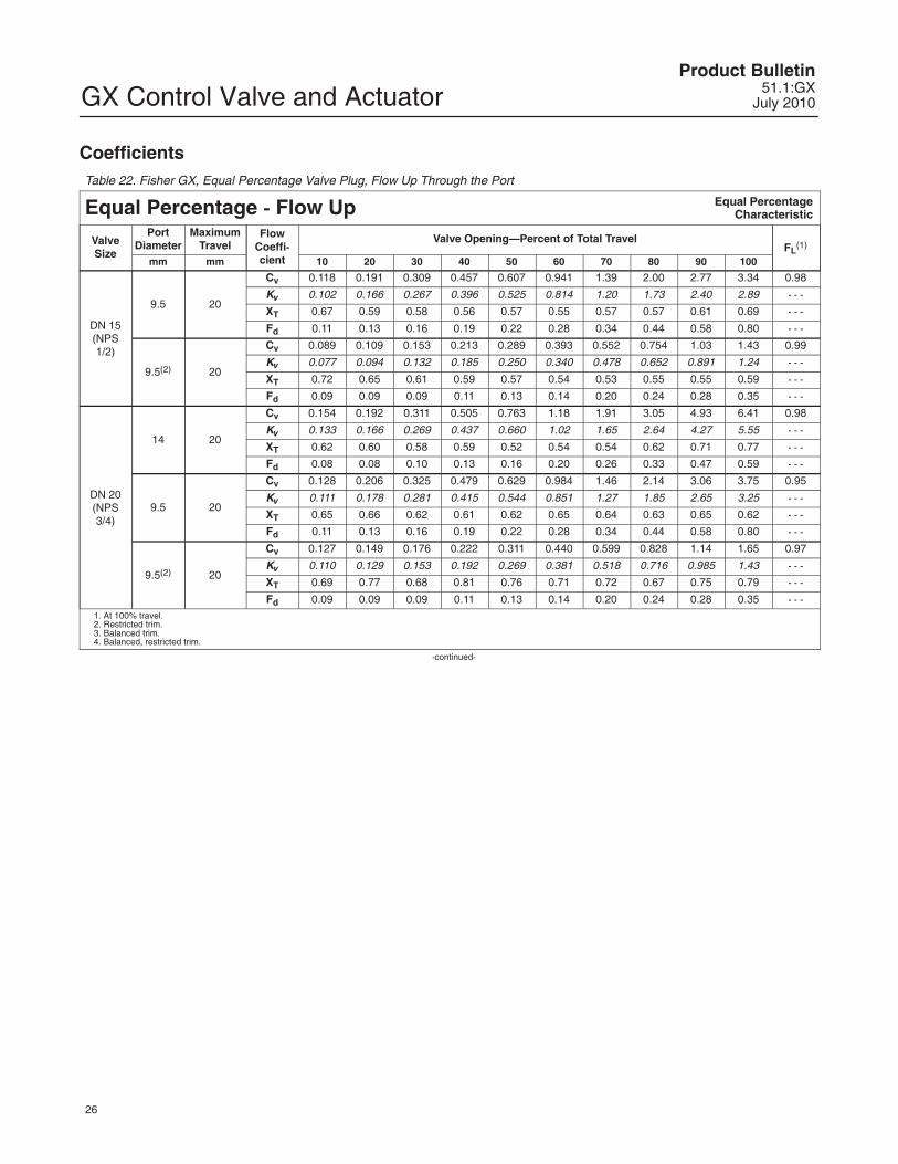
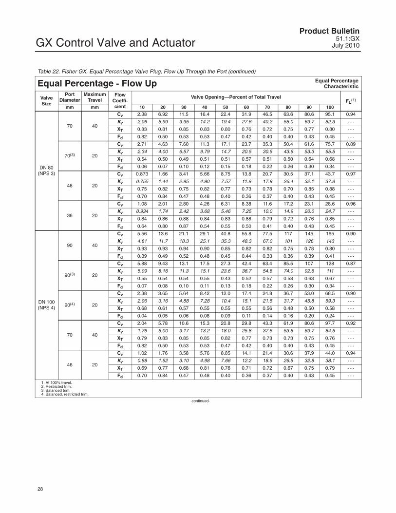
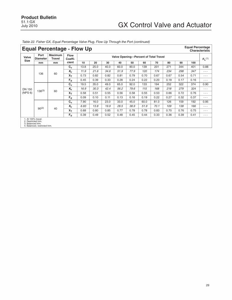
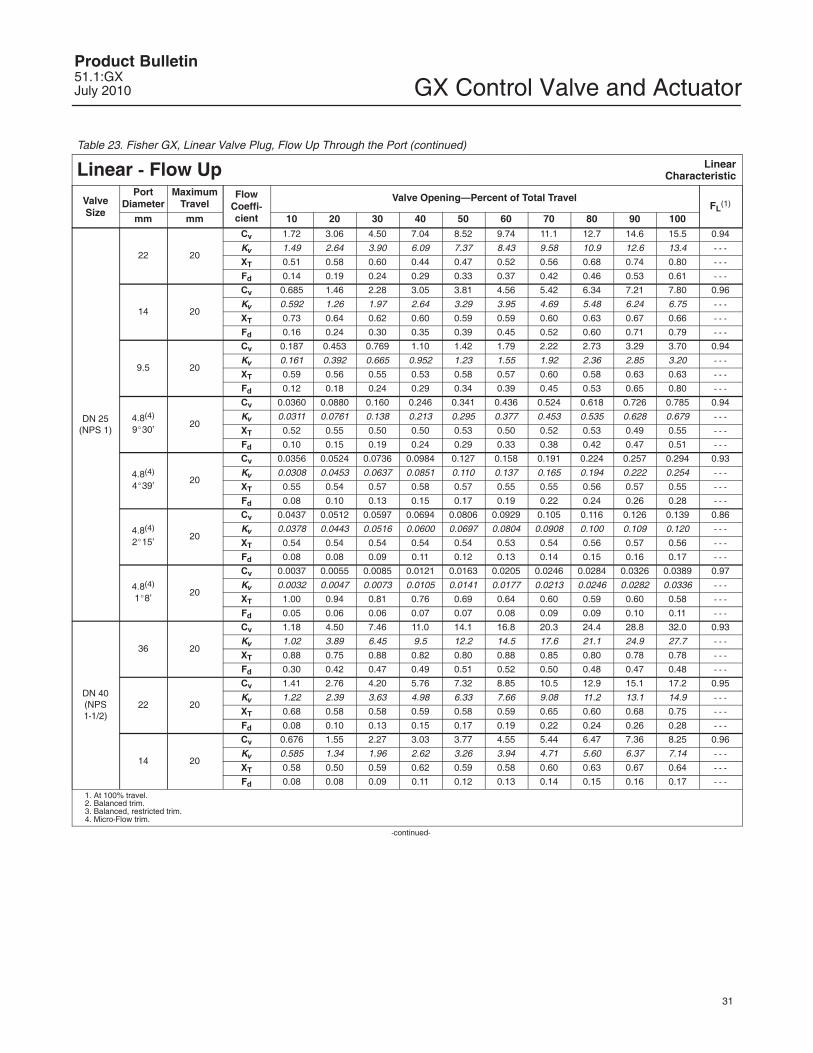
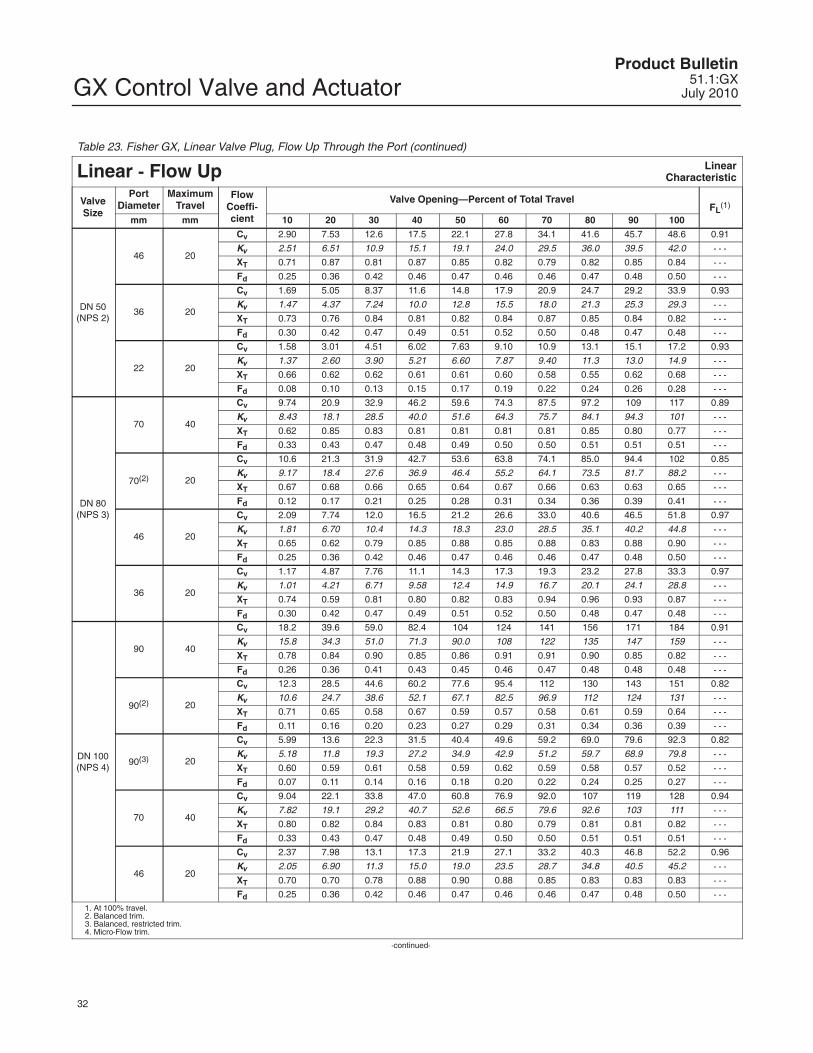
CoefficientsTable 22. Fisher GX, Equal Percentage Valve Plug, Flow Up Through the Port
Equal Percentage - Flow Up Equal PercentageCharacteristic
1. Valves should not be required to throttle at a Cv less than the specified minimum Cv for an extended period. Erosion damage to the valve seats may result.2. At 100% travel.
GX Control Valve and ActuatorProduct Bulletin51.1:GXJuly 2010
35
Note
Neither Emerson, Emerson ProcessManagement, nor any of their affiliatedentities assumes responsibility for theselection, use, or maintenance of anyproduct. Responsibility for theselection, use, and maintenance of anyproduct remains with the purchaserand end user.
GX Control Valve and ActuatorProduct Bulletin
51.1:GXJuly 2010
36
Emerson Process Management Marshalltown, Iowa 50158 USASorocaba, 18087 BrazilChatham, Kent ME4 4QZ UKDubai, United Arab EmiratesSingapore 128461 Singapore
�Fisher Controls International LLC 2003, 2010; All Rights Reserved
www.Fisher.com
The contents of this publication are presented for informational purposes only, and while every effort has been made to ensure their accuracy, theyare not to be construed as warranties or guarantees, express or implied, regarding the products or services described herein or their use orapplicability. All sales are governed by our terms and conditions, which are available upon request. We reserve the right to modify or improve thedesigns or specifications of such products at any time without notice. Neither Emerson, Emerson Process Management, nor any of their affiliatedentities assumes responsibility for the selection, use or maintenance of any product. Responsibility for proper selection, use, and maintenance ofany product remains solely with the purchaser and end user.
Fisher, FIELDVUE, Cavitrol, ValveLink, and Whisper Trim are marks owned by one of the companies in the Emerson Process Managementbusiness division of Emerson Electric Co. Emerson Process Management, Emerson, and the Emerson logo are trademarks and service marks ofEmerson Electric Co. HART is a mark owned by the HART Communications Foundation. FOUNDATION fieldbus is a mark owned by the FieldbusFoundation. All other marks are the property of their respective owners.