12
Instruction Manual Vortex Mixers
| Date post: | 05-May-2018 |
| Category: |
Documents |
| Upload: | nguyenkhuong |
| View: | 225 times |
| Download: | 0 times |
Instruction ManualVortex Mixers

TABLE OF CONTENTS
Package Contents . . . . . . . . . . . . . . . 1
Warranty . . . . . . . . . . . . . . . 1
Installation . . . . . . . . . . . . . . . 2
Maintenance & Servicing . . . . . . . . . . . . . . . 2
Environmental Conditions . . . . . . . . . . . . . . . 2
Safety Instructions . . . . . . . . . . . . . . . 3
Standards & Regulations . . . . . . . . . . . . . . . 3
Specifications . . . . . . . . . . . . . . . 4
Digital & Pulsing Vortex Mixer Control Panel . . . . . . . 5
Introduction . . . . . . . . . . . . . . . 6
Operating Instructions . . . . . . . . . . . . . . . 6-7
Head/Accessory Installation Instructions . . . . . . . . . . 8-9
Accessories . . . . . . . . . . . . . . . 10-11
PACKAGE CONTENTS
Fixed Speed, Analog, Digital or Pulsing Vortex Mixer72" (183cm) power cord* (1) cup head* (1) 3" (7.6cm) head* (1) 3" (7.6cm) rubber head coverInstruction manualWarranty card
* These accessories come with all units except the Pulsing Vortex Mixerwhich is supplied with a 1.5 to 2mL Micro-Tube Holder with built-in cuphead.
WARRANTY
Manufacturer warrants this product to be free from defects in materialand workmanship when used under normal conditions for two (2)years. Please complete and return the enclosed warranty card. Foryour reference, make a note of the serial number, date of purchaseand supplier here.
Serial No.:_______________________________________________
Date of Purchase:_________________________________________
Supplier:________________________________________________
1

ENVIRONMENTAL CONDITIONS
Operating Conditions: Indoor use only.Temperature: 18 to 33°C (64 to 91°F)Humidity: 20% to 85% relative humidity, non-condensingAltitude: 0 to 6,562 ft. (2000 M) above sea level
Non-Operating Storage:Temperature: -20 to 65°C (-4 to 149°F)Humidity: 20% to 85% relative humidity, non-condensing
Installation Category II and Pollution Degree 2 in accordance with IEC664.
INSTALLATION
Upon receiving the Fisher Vortex Mixer, check to ensure that no dam-age has occurred during shipment. It is important that any damage thatoccurred in transport is detected at the time of unpacking. If you do findsuch damage the carrier must be notified immediately.
After unpacking, place the Vortex Mixer on a level bench or table, awayfrom explosive vapors. Ensure that the surface on which the unit isplaced will withstand typical heat produced by the unit. Always placethe unit on a sturdy work surface.
The Vortex Mixer is supplied with a power cord that should be pluggedinto a properly grounded outlet. If the supplied power cord does notmeet your needs, please use an approved power cord that suits localcodes and electric supply. Replacement of the plug must be made bya qualified electrician.
MAINTENANCE & SERVICING
The Vortex Mixer is built for long, trouble-free, dependable service. Nolubrication or other technical user maintenance is required. The unitshould be given the care normally required for any electrical appliance.Avoid wetting or unnecessary exposure to fumes. Spills should beremoved promptly. DO NOT use a cleaning agent or solvent on thefront panel which is abrasive or harmful to plastics, nor one which isflammable. Always ensure the power is disconnected from the unitprior to any cleaning. If the unit ever requires service, contact yourFisher representative.
2
SAFETY INSTRUCTIONS
Please read the entire instruction manual before operating the VortexMixer.
WARNING! DO NOT use the Vortex Mixer in a hazardousatmosphere or with hazardous materials for which the unit wasnot designed. Also, the user should be aware that the protectionprovided by the equipment may be impaired if used with acces-sories not provided or recommended by the manufacturer, orused in a manner not specified by the manufacturer.
Always operate unit on a level surface for best performance andmaximum safety.
DO NOT lift the Vortex Mixer by the head. All heads, includingcup head, are removable. They can pop off if lifted by them.
CAUTION! To avoid electrical shock, completely cut off powerto the unit by disconnecting the power cord from the wall outlet.Disconnect unit from the power supply prior to maintenance andservicing.
Spills should be removed promptly. DO NOT immerse the unitfor cleaning.
DO NOT operate the unit if it shows signs of electrical ormechanical damage.
Earth Ground - Protective Conductor Terminal
Alternating Current
!
"
3
STANDARDS & REGULATIONS
Henry Troemner LLC hereby declares under it's sole responsibility thatthe construction of this product conforms in accordance with the followingstandards:
Safety standards:IEC 61010-1 Safety requirements for electrical equipment for
measurement, control and laboratory use. Part I:General Requirements.
IEC 61010-2-051 Part II: Particular requirements for laboratoryequipment for mixing and stirring.
UL Std. No. 61010-1
EMC standards:IEC45501 IEC6100-3-2/3-3IEC61000-4-2 IEC61000-4-3IEC61000-4-4 IEC61000-4-5IEC61000-4-6 IEC61000-4-11EN55022A
Associated EU guidelines:EMC directive 89/336/EECLVD directive 73/23/EECMachine directive 98/37/EC

DIGITAL & PULSING VORTEXER MIXER SPECIFICATIONS
Overall dimensions (L x W x H): 8 x 4.25 x 5"(20.3 x 10.8 x 12.7cm)
Electrical (50/60 Hz): 120V, 1.2 amps, 150 watts230V, 0.6 amps, 150 watts
Fuses: 5mm x 20mm, 5 amp quick actingSpeed range*, on mode: 500 to 3000rpm **
auto mode: 1000 to 3000rpm **pulse mode: 3000rpm **
Timer: 1 second to 9999 minutes(increased in 1 second increments)
Orbit, Digital unit: 0.194" (4.9mm)Pulsing unit: 0.098" (2.5mm)
Duty rating: intermittent dutyControls: see page 5Ship weight: 11.7lbs (5.3kg)
4
ANALOG VORTEXER MIXER SPECIFICATIONS
Overall dimensions (L x W x H): 8 x 4.25 x 5"(20.3 x 10.8 x 12.7cm)
Electrical (50/60 Hz): 120V, 1.2 amps, 150 watts230V, 0.6 amps, 150 watts
Fuses: 5mm x 20mm, 5 amp quick actingSpeed range*: 300 to 3200rpm **Orbit: 0.194" (4.9mm)Duty rating: intermittent dutyControls: auto/off/on rocker switch,
speed knob: variable 1 to 10 dial marksShip weight: 11.7lbs (5.3kg)
FIXED SPEED VORTEXER MIXER SPECIFICATIONS
Overall dimensions (L x W x H): 8 x 4.25 x 5"(20.3 x 10.8 x 12.7cm)
Electrical (50/60 Hz): 120V, 1.2 amps, 150 watts230V, 0.6 amps, 150 watts
Fuses: 5mm x 20mm, 5 amp quick actingSpeed range*: 3200rpm **Orbit: 0.194" (4.9mm)Duty rating: intermittent dutyControls: noneShip weight: 11.7lbs (5.3kg)
* Maximum speed will vary depending on accessory being used.** 230V units maximum speed: 2500rpm

DIGITAL & PULSING VORTEX MIXER CONTROL PANEL
The front panel of the Digital/Pulsing Vortex Mixer contains all theswitches, controls and displays needed to operate the unit.
A. 3-way rocker switch: Auto/standby/on rocker switch starts/stopsthe vortexing function.
B. Time display: Displays accumulated time (continuous mode) orhow much time is remaining (timed mode). The display range is from0 to 9,999 minutes in one (1) second increments. The display will indi-cate minutes and seconds until the timer reaches 99 minutes and 59seconds (99:59), then the display will automatically display minutes upto 9,999.
C. Up/down arrows for set-point control.
D. Speed display: Displays the speed of the Vortex Mixer.
E. Up/down arrows for set-point control.
F. Pulse button: Starts the pulsing mode.
B D
EC
A
F
5 * Same controls for the Digital Vortex Mixer but without the 'pulse' button.
VORTEX MIXER INTRODUCTION
Your Vortex Mixer is ready for most one-handed applications. The VortexMixer operates by mixing tubes just prior to testing.
OPERATING TIPSThese units are not intended for continuous use over extended periodsof time. A built-in temperature sensor will prevent the unit from over-heating by shutting the motor down. If this occurs, allow the motor tocool down and the unit will be able to resume normal operation.Decrease the duration of the time unit is used between rest periods.
See page 8-9 for 'Head/Accessory Installation Instructions'.
FIXED SPEED VORTEX MIXER OPERATING INSTRUCTIONS
The Fixed Speed Vortex Mixer runs only at 3200rpm (2500rpm for 230V).
1. Plug the power cord into a properly grounded outlet. The unit is nowon and in a standby mode.
2. The vessel you are using must be pushed down on the head attachmentto achieve motion. To get the desired mix, vary the angle of contactand pressure against the head.
3. The mixer will return to standby mode when the vessel is lifted offthe head.
4. The unit can become warm to the touch with constant use. There isnothing wrong with it. At high performance settings the motor (ULrecognized component) simply puts out more heat. IMPORTANT:DO NOT use large accessories on the Fixed Speed Vortex Mixer.This unit is designed for use with cup head or 3" (7.6cm) head with3" (7.6cm) rubber head cover only.
5. To completely cut off power to the unit, disconnect the power cordfrom the wall outlet.
ANALOG VORTEX MIXER OPERATING INSTRUCTIONS
1. Make sure the 3-way rocker switch is in the center, off position. Plugthe power cord into a properly grounded outlet.
2. For continuous operation, push the rocker switch to the right, onposition. For intermittent/touch operation, push the rocker switch tothe left, auto position.
3. In either case, turn the speed knob to 1. In the on position, you willsee the head in motion immediately. In the auto position, the vesselyou are using must be pushed down on the head attachment toachieve motion. To get the desired mix, vary the speed, using thespeed knob, and/or vary the angle of contact and pressure againstthe head.
4. When finished with either continuous or intermittent operation, returnrocker switch to the center, off position.
5. The continuous, on mode is for the larger accessories. In continuouson mode, DO NOT run the unit above 900rpm (analog speed settingof approximately 5).
6. The intermittent, auto mode is intended for short mixing times of one(1) minute or less at full speed. A rest period of two (2) minutes isrecommended to minimize the possibility of overheating the motor.The unit can become warm to the touch with constant use. There isnothing wrong with it. At high performance settings the motor (ULrecognized component) simply puts out more heat. IMPORTANT:When using larger accessories (Insert Retainer with foam inserts orAmpule Tube Holders), DO NOT run the unit above 900rpm, (analogspeed setting of approximately 5). UNIT DAMAGE WILL OCCUR.
7. To completely cut off power to the unit, disconnect the power cordfrom the wall outlet.
6
DIGITAL & PULSING VORTEX MIXER OPERATING INSTRUCTIONS
1. Make sure the 3-way rocker switch is in the center, standby position.Plug the power cord into a properly grounded outlet. The unit is nowon and in a standby mode.
2. For continuous operation, push the rocker switch to the right, onposition. For intermittent/touch operation, push the rocker switch tothe left, auto position.
3. In either case, set the speed. In the on position, you will see thehead in motion immediately. In the auto position, the vessel you areusing must be pushed down on the head attachment to achievemotion. To get the desired mix, vary the speed, using the speedup/down arrows, and/or vary the angle of contact and pressureagainst the head.
Setting speed:To set the speed press the up/down arrows below the speed displayuntil you reach the desired speed.
• Speed while running in the on position is 500 to 3000rpm (500to 2500rpm for 230V).
• Speed while running in the auto position is 1000 to 3000rpm(1000 to 2500rpm for 230V).
• Speed while running in the pulse mode is 3000rpm, running for30 seconds, resting 10 seconds (2500rpm for 230V).
Setting time:Time operation works in both auto and on positions.
• To run in timed mode (programmed time), start by pressing therocker switch to the left, auto position. Press the up/downarrows below the time display until you reach the desired time.While running unit in timed mode, the time display will showtime remaining, counting down to zero (0:00).
• To run in continuous mode (accumulated time), reset the timer
to zero (0:00) before running. Time display will show theaccumulated time and run until you press the rocker switch tothe center, standby position.
Pulse operation: (for Pulsing Vortex Mixer only)• Set the time if desired.• Move the rocker switch to the right, on position. Press the
pulse button, in the center of the front panel. The speed displaywill show "PULSE". The unit will run at 3000rpm, cycling a runtime of 30 seconds, followed by a resting time of 10 seconds.The unit will continue vortexing until the timer reaches zero(0:00) or you stop the unit by moving the rocker switch to thecenter, standby position.
4. When finished with either continuous, intermittent or pulse operation,return rocker switch to the center, standby position.
5. The continuous, on mode is for the larger accessories. In continuouson mode, DO NOT run the unit above 900rpm.
6. The intermittent, auto mode is intended for short mixing times of one(1) minute or less at full speed. A rest period of two (2) minutes isrecommended to minimize the possibility of overheating the motor.The unit can become warm to the touch with constant use. There isnothing wrong with it. At high performance settings the motor (ULrecognized component) simply puts out more heat. IMPORTANT:When using larger accessories (Insert Retainer with foam inserts orAmpule Tube Holders), DO NOT run the unit above 900rpm. UNITDAMAGE WILL OCCUR.
7. To completely cut off power to the unit, disconnect the power cordfrom the wall outlet.
7
HEAD/ACCESSORY INSTALLATION INSTRUCTIONS
8
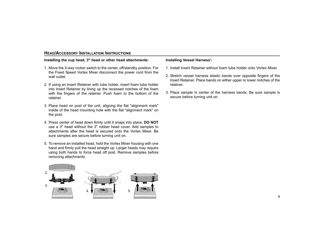
Installing the cup head, 3" head or other head attachments:
1. Move the 3-way rocker switch to the center, off/standby position. For the Fixed Speed Vortex Mixer disconnect the power cord from thewall outlet.
2. If using an Insert Retainer with tube holder, insert foam tube holderinto Insert Retainer by lining up the recessed notches of the foamwith the fingers of the retainer. Push foam to the bottom of theretainer.
3. Place head on post of the unit, aligning the flat "alignment mark"inside of the head mounting hole with the flat "alignment mark" onthe post.
4. Press center of head down firmly until it snaps into place. DO NOTuse a 3" head without the 3" rubber head cover. Add samples toattachments after the head is secured onto the Vortex Mixer. Besure samples are secure before turning unit on.
5. To remove an installed head, hold the Vortex Mixer housing with onehand and firmly pull the head straight up. Larger heads may requireusing both hands to force head off post. Remove samples beforeremoving attachments.
Installing Vessel Harness':
1. Install Insert Retainer without foam tube holder onto Vortex Mixer.
2. Stretch vessel harness elastic bands over opposite fingers of theInsert Retainer. Place bands on either upper or lower notches of theretainer.
3. Place sample in center of the harness bands. Be sure sample issecure before turning unit on.
5.4.3.
2.

HEAD/ACCESSORY INSTALLATION INSTRUCTIONS
Installing Single Tube Holder:
1. Move the 3-way rocker switch to the center, off/standby position.Single Tube Holder should NOT be used on the Fixed Speed VortexMixer.
2. Remove cup head, or any other accessory from the Vortex Mixer.
3. Align the base plate of the Single Tube Holder over the post of the Vortex Mixer with the two Single Tube Holder alignment posts at theback of the unit. Lower Single Tube Holder onto Vortex Mixer, themagnets will hold the Single Tube Holder in place. To realign thisattachment, pull up from the handle until the magnets release, checkthe alignment and place again.
4. Now that the Single Tube Holder is in place, attach the cup head onthe post of the unit, aligning the flat "alignment mark" inside of thehead mounting hole with the flat "alignment mark" on the post.
5. Lift up on the spring loaded upper portion of the Single Tube Holderand slide a 2.5 to 4.5" (6.4 to 11.4cm) long tube on the cup head sothat the tube is aligned in the middle. The 0.5mL Micro-Tube Holderor the 1.5 to 2mL Micro-Tube Holder will also fit into the Single TubeHolder. You are now ready to mix your sample.
9
2. 5.5.4.3.
10
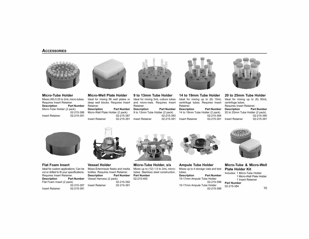
Micro-Tube Holder Mixes (48) 0.25 to 2mL micro-tubes.Requires Insert Retainer.Description Part NumberMicro-Tube Holder (2 pack)
02-215-386Insert Retainer 02-215-391
Vessel HolderMixes Erlenmeyer flasks and mediabottles. Requires Insert Retainer.Description Part NumberVessel Harness (2 pack)
02-215-392Insert Retainer 02-215-391
14 to 19mm Tube Holder Ideal for mixing up to (8) 15mLcentrifuge tubes. Requires InsertRetainer.Description Part Number14 to 19mm Tube Holder (2 pack)
02-215-394Insert Retainer 02-215-391
9 to 13mm Tube HolderIdeal for mixing 5mL culture tubesand micro-vials. Requires InsertRetainer.Description Part Number9 to 13mm Tube Holder (2 pack)
02-215-393Insert Retainer 02-215-391
Micro-Well Plate Holder Ideal for mixing 96 well plates ordeep well blocks. Requires InsertRetainer.Description Part NumberMicro-Well Plate Holder (2 pack)
02-215-387Insert Retainer 02-215-391
20 to 25mm Tube Holder Ideal for mixing up to (8) 50mLcentrifuge tubes.Requires Insert Retainer.Description Part Number20 to 25mm Tube Holder (2 pack)
02-215-395Insert Retainer 02-215-391
Ampule Tube HolderMixes up to 4 storage vials and testtubes.Description Part Number15-17mm Ampule Tube Holder
02-215-39810-17mm Ampule Tube Holder
02-215-399
ACCESSORIES
Flat Foam InsertIdeal for custom applications. Can becut or drilled to fit your specifications.Requires Insert Retainer.Description Part NumberFlat Foam Insert (2 pack)
02-215-397Insert Retainer 02-215-391
Micro-Tube Holder, s/sMixes up to (12) 1.5 to 2mL micro-tubes. Stainless steel construction.Part Number02-215-400
Micro-Tube & Micro-WellPlate Holder KitIncludes: 1 Micro-Tube Holder
1 Micro-Well Plate Holder1 Insert Retainer
Part Number02-215-384

For customer service call 1-800-766-7000To fax an order, use 1-800-928-1166To order online: www.fishersci.com
715028-00 (REV 1)
3" Rubber Head Cover &3" HeadDesigned for mixing irregular shapedobjects.Description Part Number3" Rubber Head Cover
02-215-3833" Head 02-215-382
Cup HeadDesigned for mixing one tube at atime.Part Number02-215-380
Tube Holder KitIncludes: (1) 9-13mm Tube Holder
(1) 14-19mm Tube Holder(1) 20-25mm Tube Holder1 Flat Foam Insert2 Vessel Harness'1 Insert Retainer
Part Number02-215-388
Single Tube HolderSingle tube, hands free mixing.Easily attaches to the top of anyVortex Mixer with the use of a strongmagnetic base. Accepts tubes from2.5 to 4.5" (6.4 to 11.4cm) in length.Minimum tube diameter of 0.75"(1.9cm).Part Number02-215-404
11
ACCESSORIES
Adapter for Vortex-Genie® Mixer*Adapter plate easily adheres to theVortex-Genie® Mixer housing soSingle Tube Holder (sold separate-ly) can be attached.Part Number02-215-405
* The Vortex-Genie® Mixer is a registeredtrademark of Scientific Industries, Inc.
0.5mL Micro-Tube HolderMixes (24) 0.5mL micro-tubes. Foruse with Single Tube Holder.Part Number02-215-402
1.5 to 2mL Micro-TubeHolderMixes (18) 1.5 to 2mL micro-tubes.For use with Single Tube Holder.Part Number02-215-403


