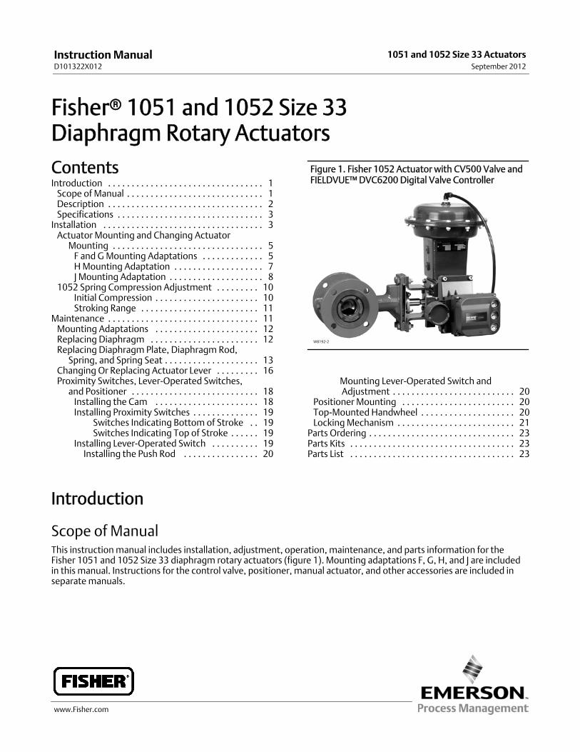
www.Fisher.com Fisherr 1051 and 1052 Size 33 Diaphragm Rotary Actuators Contents Introduction 1 ................................. Scope of Manual 1 ............................. Description 2 ................................. Specifications 3 ............................... Installation 3 .................................. Actuator Mounting and Changing Actuator Mounting 5 ................................ F and G Mounting Adaptations 5 ............. H Mounting Adaptation 7 ................... J Mounting Adaptation 8 .................... 1052 Spring Compression Adjustment 10 ......... Initial Compression 10 ...................... Stroking Range 11 ......................... Maintenance 11 ................................ Mounting Adaptations 12 ...................... Replacing Diaphragm 12 ....................... Replacing Diaphragm Plate, Diaphragm Rod, Spring, and Spring Seat 13 .................... Changing Or Replacing Actuator Lever 16 ......... Proximity Switches, Lever-Operated Switches, and Positioner 18 ........................... Installing the Cam 18 ...................... Installing Proximity Switches 19 .............. Switches Indicating Bottom of Stroke 19 .. Switches Indicating Top of Stroke 19 ...... Installing Lever-Operated Switch 19 .......... Installing the Push Rod 20 ................ Figure 1. Fisher 1052 Actuator with CV500 Valve and FIELDVUE™ DVC6200 Digital Valve Controller W8192-2 Mounting Lever-Operated Switch and Adjustment 20 .......................... Positioner Mounting 20 ........................ Top-Mounted Handwheel 20 .................... Locking Mechanism 21 ......................... Parts Ordering 23 ............................... Parts Kits 23 ................................... Parts List 23 ................................... Introduction Scope of Manual This instruction manual includes installation, adjustment, operation, maintenance, and parts information for the Fisher 1051 and 1052 Size 33 diaphragm rotary actuators (figure 1). Mounting adaptations F, G, H, and J are included in this manual. Instructions for the control valve, positioner, manual actuator, and other accessories are included in separate manuals. Instruction Manual D101322X012 1051 and 1052 Size 33 Actuators September 2012
Scope of ManualThis instructionmanual includes installation, adjustment, operation, maintenance, and parts information for theFisher 1051 and 1052 Size 33 diaphragm rotary actuators (figure 1). Mounting adaptations F, G, H, and J are includedin this manual. Instructions for the control valve, positioner, manual actuator, and other accessories are included inseparatemanuals.
InstructionManualD101322X012
1051 and 1052 Size 33 ActuatorsSeptember 2012
InstructionManualD101322X012
1051 and 1052 Size 33 ActuatorsSeptember 2012
2
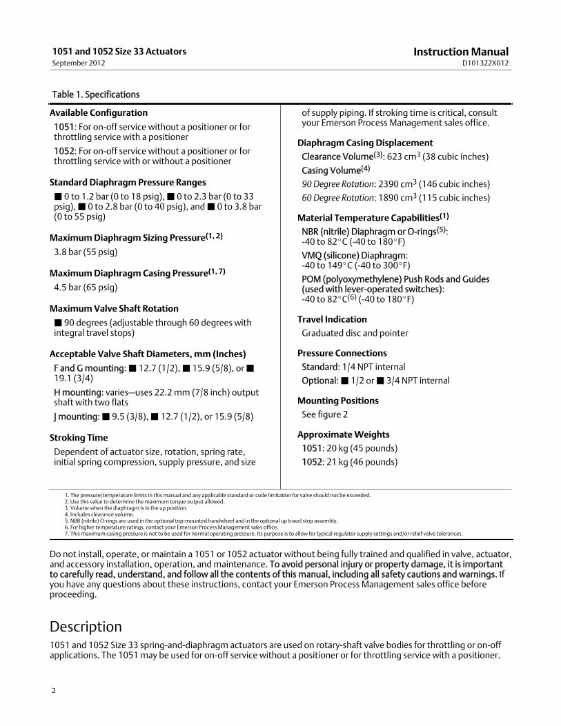
Table 1. Specifications
Available Configuration
1051: For on-off service without a positioner or forthrottling service with a positioner
1052: For on-off service without a positioner or forthrottling service with or without a positioner
Standard Diaphragm Pressure Ranges
J 0 to 1.2 bar (0 to 18 psig),J 0 to 2.3 bar (0 to 33psig),J 0 to 2.8 bar (0 to 40 psig), andJ 0 to 3.8 bar(0 to 55 psig)
MaximumDiaphragm Sizing Pressure(1, 2)
3.8 bar (55 psig)
MaximumDiaphragm Casing Pressure(1, 7)
4.5 bar (65 psig)
MaximumValve Shaft Rotation
J 90 degrees (adjustable through 60 degrees withintegral travel stops)
Acceptable Valve Shaft Diameters, mm (Inches)
F and Gmounting:J 12.7 (1/2),J 15.9 (5/8), orJ19.1 (3/4)
Hmounting: varies–uses 22.2mm (7/8 inch) outputshaft with two flats
J mounting:J 9.5 (3/8),J 12.7 (1/2), or 15.9 (5/8)
Stroking Time
Dependent of actuator size, rotation, spring rate,initial spring compression, supply pressure, and size
of supply piping. If stroking time is critical, consultyour Emerson Process Management sales office.
Diaphragm Casing Displacement
Clearance Volume(3): 623 cm3 (38 cubic inches)
Casing Volume(4)
90 Degree Rotation: 2390 cm3 (146 cubic inches)
60 Degree Rotation: 1890 cm3 (115 cubic inches)
Material Temperature Capabilities(1)
NBR (nitrile) Diaphragm or O-rings(5):-40 to 82_C (-40 to 180_F)
VMQ (silicone) Diaphragm:-40 to 149_C (-40 to 300_F)
POM (polyoxymethylene) Push Rods and Guides(used with lever-operated switches):-40 to 82_C(6) (-40 to 180_F)
Travel Indication
Graduated disc and pointer
Pressure Connections
Standard: 1/4 NPT internal
Optional:J 1/2 orJ 3/4 NPT internal
Mounting Positions
See figure 2
ApproximateWeights
1051: 20 kg (45 pounds)
1052: 21 kg (46 pounds)
1. The pressure/temperature limits in this manual and any applicable standard or code limitation for valve should not be exceeded.2. Use this value to determine themaximum torque output allowed.3. Volume when the diaphragm is in the up position.4. Includes clearance volume.5. NBR (nitrile) O-rings are used in the optional top-mounted handwheel and in the optional up travel stop assembly.6. For higher temperature ratings, contact your Emerson Process Management sales office.7. This maximum casing pressure is not to be used for normal operating pressure. Its purpose is to allow for typical regulator supply settings and/or relief valve tolerances.
Do not install, operate, or maintain a 1051 or 1052 actuator without being fully trained and qualified in valve, actuator,and accessory installation, operation, andmaintenance. To avoid personal injury or property damage, it is importantto carefully read, understand, and follow all the contents of this manual, including all safety cautions and warnings. Ifyou have any questions about these instructions, contact your Emerson Process Management sales office beforeproceeding.
Description1051 and 1052 Size 33 spring-and-diaphragm actuators are used on rotary-shaft valve bodies for throttling or on-offapplications. The 1051may be used for on-off service without a positioner or for throttling service with a positioner.
InstructionManualD101322X012
1051 and 1052 Size 33 ActuatorsSeptember 2012
3
The 1052 uses an adjustable spring seat to control spring compression. It may be used for on-off service without apositioner, or it may be used for throttling service with or without a positioner, depending on service conditions.
A top-mounted handwheel may bemounted for infrequent service as amanual override. Amanual actuator isrecommended for routine and repeatedmanual operation. Externally adjustable travel stops are used to limit thedegree of rotation at both ends of the actuator stroke. Provisions are included for integral mounting of optionalmagnetic proximity switches. Lever-operated, mechanical switches are also available.
The lever for the 1051 and 1052 size 33 actuator is supported by bushings. The levermay be changed toaccommodate valve bodies with different size valve shafts and differentmounting adaptations. Levers and accessoriesare available for mounting valve bodies and equipment with the followingmounting adaptations:
F and Gmounting adaptations (figures 9 and 10) are for use with Fisher splined-shaft rotary valve bodies with 12.7,15.9, and 19.1mm (1/2, 5/8, and 3/4 inch) valve shaft diameters. A stub shaft is available for installation on the end ofthe lever opposite the valve body for use as a wrench-operated extension (for emergency override) or as ameans ofconnecting amanual actuator (see figure 14).
Hmounting (figure 11) is for use with non-Fisher products and user-providedmounting brackets and shaft couplings.It includes amounting surface with threaded holes for attaching the user-providedmounting bracket. A 22.2mm (7/8inch) stub shaft with flats is pinned to the lever and is used to couple the actuator to the operated equipment. Asecond stub shaft may be installed on the opposite end of the lever for use as a wrench-operated extension (foremergency override) or as ameans for connecting amanual actuator (see figure 14). Stub shafts are available instandard and reverse constructions (see figure 12) to provide proper operation with themounting position andactuator action desired (see figure 2).
J mounting (figure 13) permits use of the actuator with Fisher keyed-shaft valve bodies and other keyed-shaftequipment with 9.5, 12.7, and 15.9mm (3/8, 1/2, and 5/8 inch) shaft diameters. A stub shaft is pinned to the lever anda valve shaft coupling is pinned to the stub shaft. The coupling hasmultiple keyways (see figure 4) to accommodatemounting in the desired position. A second stub shaft may be installed on the opposite end of the lever for use as awrench-operated extension (for emergency override) or as ameans for connecting amanual actuator (see figure 14).
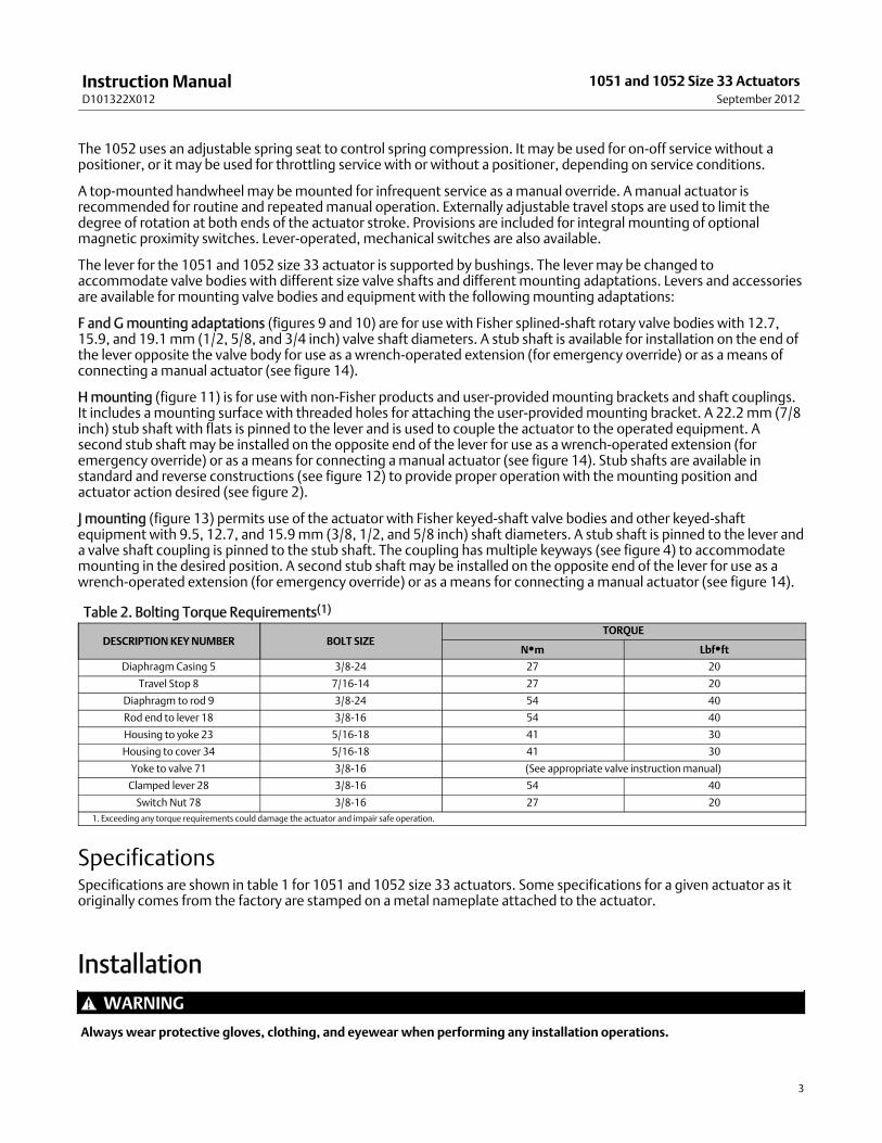
Table 2. Bolting Torque Requirements(1)
DESCRIPTION KEYNUMBER BOLT SIZETORQUE
NSm LbfSftDiaphragmCasing 5 3/8-24 27 20
Travel Stop 8 7/16-14 27 20
Diaphragm to rod 9 3/8-24 54 40
Rod end to lever 18 3/8-16 54 40
Housing to yoke 23 5/16-18 41 30
Housing to cover 34 5/16-18 41 30
Yoke to valve 71 3/8-16 (See appropriate valve instructionmanual)
Clamped lever 28 3/8-16 54 40
Switch Nut 78 3/8-16 27 201. Exceeding any torque requirements could damage the actuator and impair safe operation.
SpecificationsSpecifications are shown in table 1 for 1051 and 1052 size 33 actuators. Some specifications for a given actuator as itoriginally comes from the factory are stamped on ametal nameplate attached to the actuator.
InstallationWARNING
Alwayswear protective gloves, clothing, and eyewear when performing any installation operations.
InstructionManualD101322X012
1051 and 1052 Size 33 ActuatorsSeptember 2012
4
Checkwith your process or safety engineer for any other hazards thatmay be present from exposure to processmedia.
If installing into an existing application, also refer to theWARNING at the beginning of theMaintenance section in thisinstructionmanual.
MOUNTING ACTION(1)
VALVE SERIES ORDESIGN VALVE SERIES OR DESIGN
BALL/PLUGROTATION TO
CLOSEV250 V150, V200 & V300
CV500V500
DISC/BALLROTATION TO
CLOSEV250
8510B, 8532,8560& 9500
Right-Hand PDTCPDTO
CCWCCW
AB
AB
AB
CWCW
NANA
BA
Left-Hand PDTCPDTO
CCWCCW
NANA
DC
DC
CWCW
CD
CD
Left-Hand(Optional)(2)
PDTCPDTO
CWCW
NANA
CD
NANA
NANA
NANA
NANA
1. PDTC–Push-down-to-close, and PDTO–Push-down-to-open.2. A left hand ball will be required for the NPS 3 through 12 Series B and the NPS 14 to 20, with or without attenuator.
Figure 2. Mounting Styles and Positions for Fisher 1051 and 1052 Actuators
1
NOTES:POSITION 1 IS STANDARD; POSITIONS 2 THROUGH 4
(SHOWN IN DOTTED LINES) ARE ALTERNATIVES.1
STYLE D
STYLE C
STYLE B
STYLE A
RIGHT-HANDMOUNTING
43A6505-AA1584-3
STYLE A STYLE B
STYLE D STYLE C
FLOW
FLOW
RIGHT-HANDMOUNTING
LEFT-HANDMOUNTING
POSITION 1 POSITION 1
POSITION 1 POSITION 1
4
3
2 4
3
2
4
3
2 4
3
2LEFT-HANDMOUNTING
1
11
InstructionManualD101322X012
1051 and 1052 Size 33 ActuatorsSeptember 2012
5
CAUTION
To avoid parts damage, do not use an operating pressure that exceeds theMaximumDiaphragmCasing Pressure (table 1)or produces a torque greater than theMaximumAllowable Valve Shaft Torque (see Catalog 14). Use pressure-limiting orpressure-relieving devices to prevent the diaphragm casing pressure from exceeding its limit.
The actuator, as it comes from the factory, is normally mounted on a valve body. Follow the procedures given in thevalve instructionmanual when installing the control valve in the pipeline.
If a positioner is ordered with the actuator, the pressure connection to the actuator is normally made at the factory. Ifit is necessary tomake this connection, run either 1/4 inch pipe or 3/8 inch tubing (for standard diaphragm casefittings) between the pressure connection and the instrument. Keep the length of tubing or pipe as short as possible toavoid transmission lag in the control signal.
When the control valve is completely installed and connected to the controlling instrument, check tomake sure thatthe action is correct (air-to-open or air-to-close) and that the controlling instrument is properly configured for thedesired action. For successful operation, the diaphragm rod, lever, and valve shaft must move freely in response tochanges in the loading pressure on the diaphragm.
Actuator Mounting and Changing Actuator MountingUse the following steps tomount the actuator or to change actuatormounting style or position.
F and GMounting AdaptationsUnless otherwise specified, key numbers referenced in the following procedures are shown in figure 9 for the 1051actuator and in figure 10 for the 1052 actuator.
1. Proceed as appropriate:
If the Actuator is mounted on a valve body and it is necessary to changemounting style or position, the actuator mustfirst be separated from the valve body. Proceed to the Disassembly portion of the Changing or Replacing ActuatorLever procedure, observe all warnings, perform steps 1 through 6, and return to step 2 which follows.
If the Actuator is not mounted on a valve body, proceed to the Disassembly portion of the Changing or ReplacingActuator Lever procedure, perform steps 2 through 5, and return to step 2 which follows.
2. Refer to figure 2 for available mounting styles and positions. Whenmounting on a Vee-Ball™ V150, V200 or V300valve, check the valvemanual to determine if it is Series B. The actuator is normally positioned vertically with thevalve in a horizontal pipeline.
3. Determine whether the actuator mounting yoke (key 22) will bemounted on the housing cover assembly (key 33)side or on the actuator housing boss side of the actuator. If the desiredmounting position and style requiremovingthemounting yoke and travel indicator (key 35) to opposite sides of the actuator, remove themachine screws (key38), the travel indicator pointer (key 37), themachine screws, and the travel indicator scale (key 35). Remove thecap screws (key 23) and themounting yoke. Install themounting yoke in the desired position (on the housing coverassembly or on the actuator housing boss). See table 2 for recommended torque for themounting cap screws.Install the travel indicator components on the opposite side of the actuator. See figure 14 for travel indicatorcomponents used with wrench-operated extensions andmanual actuators.
4. Before sliding the valve shaft into the lever, position the valve ball or disc as follows:
For push-down-to-close action, the valve ball or disc should be in the fully open position.
InstructionManualD101322X012
1051 and 1052 Size 33 ActuatorsSeptember 2012
6
For push-down-to-open action, the valve ball or disc should be in the fully closed position (see the valve bodyinstructionmanual).
5. Make sure that the indexmarkings on the valve shaft are properly aligned with themarkings on the lever and slidethe valve shaft into the lever. Install the valvemounting cap screws, washers, and nuts and tighten to the torquevalue given in the appropriate valve body instructionmanual.
6. Ensure all end play in the valve shaft is removed by pulling the valve shaft toward the actuator as much as possible.Make sure the actuator rod is perpendicular to the valve shaft. Refer to the valve instructionmanual for specific endplay considerations.
Figure 3.Travel Stops and Switch Positions on the Fisher 1051 and 1052 Size 33 ActuatorHOUSING COVERASSEMBLY (KEY 33) PROXIMITY
SWITCHES
MOUNTING POSITION FORSWITCH INDICATINGTOPOF STROKE(ACTIVATED BYOUTER CAM)
YOKEMOUNTINGBOSSUP TRAVELSTOP
DOWN TRAVEL STOPMOUNTING POSITION FOR SWITCHINDICATING BOTTOMOF STROKE(ACTIVATED BY INNER CAM)
W4738
7. Tighten the socket head cap screwwhich compresses the splined lever connection to the valve shaft (see table 2).
CAUTION
When adjusting the travel stop for the closed position of the valve ball or disc, refer to the appropriate valve instructionmanual for detailed procedures. Undertravel or overtravel at the closed positionmay result in poor valve performanceand/or damage to the equipment.
8. Adjust the up travel stop (see figure 3) so that the valve ball or disc is in the desired position.
WARNING
To avoid personal injury and equipment damage frommoving parts, keep fingers and tools clear while stroking theactuator with the cover removed.
9. Stroke the actuator and adjust the down travel stop so that the valve ball or disc is in the desired position.
InstructionManualD101322X012
1051 and 1052 Size 33 ActuatorsSeptember 2012
7
10. Make sure that the travel indicator pointer matches the ball or disc position. Remove and install in the properposition if necessary.
11. Install the cover plate or switchmounting plate (key 59) with cap screws (key 60).
12. Refer to the table of contents for accessory installation procedures.
HMounting AdaptationUnless otherwise specified, key numbers referenced in the following procedures are shown in figure 9 for the 1051actuator and in figure 10 for the 1052 actuator. Unique parts used for the Hmounting adaptation are shown in figure11 for single stub shaft construction and in figure 14 for dual stub shaft construction.
1. To changemounting style or position, the actuator must be separated from the valve body (or other operatedequipment). Remove the cap screws used to attach the actuator to the valve body (or other operated equipment)and remove the actuator.
2. Determine the desiredmounting position. Note that stub shafts are available in standard and reverse constructionsso that proper alignment with the operated equipment can be achieved (see figure 12). Refer to figure 2 foravailable mounting styles and positions.
3. If it is necessary to install or change stub shaft(s), the actuator lever (key 27) must be removed. Perform allapplicable operations in the Disassembly portion of the Changing or Replacing Actuator Lever procedure. Install thestub shafts for the construction desired (refer to figures 11 and 14) and reassemble the actuator.
4. Determine whether the operated equipment will bemounted on the housing cover assembly (key 33) side or onthe actuator housing boss side of the actuator. Depending on the desiredmounting style and position, it may benecessary tomove the operated equipment and travel indicator components to opposite sides of the actuator. Ifso, remove the travel indicator components, the operated equipment, and themounting bracket if used. Install theoperated equipment or mounting bracket in the desired position (on the housing cover assembly or on the actuatorhousing boss). See table 2 for recommended torque for themounting cap screws. Install the travel indicatorcomponents on the side of the actuator opposite the operated equipment. Refer to figure 14 for travel indicatorcomponents used with wrench-operated extensions andmanual actuators.
5. Before coupling the operated equipment to the actuator stub shaft, position the equipment as follows:
For push-down-to-activate (open) action, the equipment should be in the fully deactivated (closed) position.
For push-down-to-deactivate (close) action, the equipment should be in the fully activated (open) position.
6. Install the required shaft coupling and the operated equipment.
CAUTION
When adjusting the travel stops to limit rotation, be certain that the rotation produced does not exceed the safe limit of theoperated equipment. Undertravel or overtravel may result in poor performance and/or damage to the equipment.
7. Adjust the up travel stop (see figure 3) so that the operated equipment is in the desired position.
WARNING
To avoid personal injury and equipment damage frommoving parts, keep fingers and tools clear while stroking theactuator with the cover removed.
8. Stroke the actuator and adjust the down travel stop so that the operated equipment is in the desired position.
InstructionManualD101322X012
1051 and 1052 Size 33 ActuatorsSeptember 2012
8
9. Make sure that the travel indicator pointer matches the ball or disc position. Remove and install in the properposition if necessary.
10. Refer to the table of contents for accessory installation procedures.
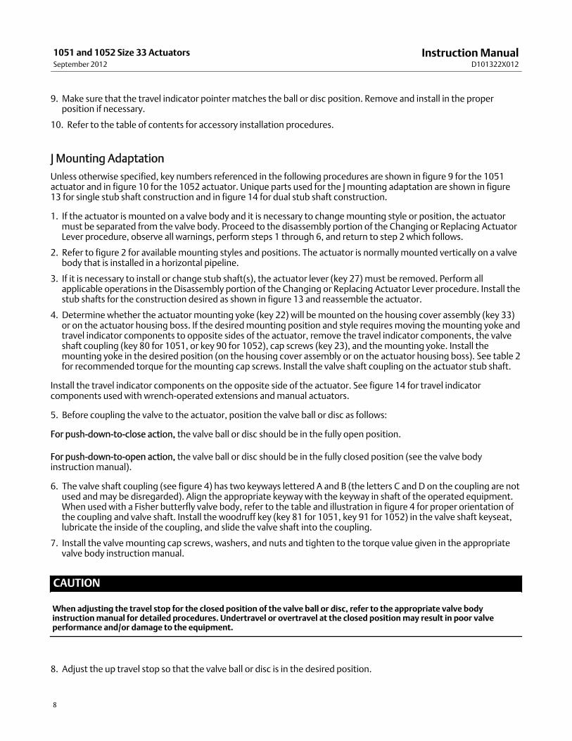
J Mounting Adaptation
Unless otherwise specified, key numbers referenced in the following procedures are shown in figure 9 for the 1051actuator and in figure 10 for the 1052 actuator. Unique parts used for the J mounting adaptation are shown in figure13 for single stub shaft construction and in figure 14 for dual stub shaft construction.
1. If the actuator is mounted on a valve body and it is necessary to changemounting style or position, the actuatormust be separated from the valve body. Proceed to the disassembly portion of the Changing or Replacing ActuatorLever procedure, observe all warnings, perform steps 1 through 6, and return to step 2 which follows.
2. Refer to figure 2 for availablemounting styles and positions. The actuator is normally mounted vertically on a valvebody that is installed in a horizontal pipeline.
3. If it is necessary to install or change stub shaft(s), the actuator lever (key 27) must be removed. Perform allapplicable operations in the Disassembly portion of the Changing or Replacing Actuator Lever procedure. Install thestub shafts for the construction desired as shown in figure 13 and reassemble the actuator.
4. Determine whether the actuator mounting yoke (key 22) will bemounted on the housing cover assembly (key 33)or on the actuator housing boss. If the desiredmounting position and style requires moving themounting yoke andtravel indicator components to opposite sides of the actuator, remove the travel indicator components, the valveshaft coupling (key 80 for 1051, or key 90 for 1052), cap screws (key 23), and themounting yoke. Install themounting yoke in the desired position (on the housing cover assembly or on the actuator housing boss). See table 2for recommended torque for themounting cap screws. Install the valve shaft coupling on the actuator stub shaft.
Install the travel indicator components on the opposite side of the actuator. See figure 14 for travel indicatorcomponents used with wrench-operated extensions andmanual actuators.
5. Before coupling the valve to the actuator, position the valve ball or disc as follows:
For push-down-to-close action, the valve ball or disc should be in the fully open position.
For push-down-to-open action, the valve ball or disc should be in the fully closed position (see the valve bodyinstructionmanual).
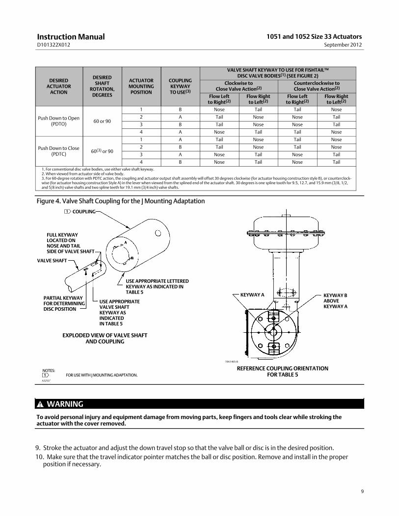
6. The valve shaft coupling (see figure 4) has two keyways lettered A and B (the letters C and D on the coupling are notused andmay be disregarded). Align the appropriate keyway with the keyway in shaft of the operated equipment.When used with a Fisher butterfly valve body, refer to the table and illustration in figure 4 for proper orientation ofthe coupling and valve shaft. Install the woodruff key (key 81 for 1051, key 91 for 1052) in the valve shaft keyseat,lubricate the inside of the coupling, and slide the valve shaft into the coupling.
7. Install the valvemounting cap screws, washers, and nuts and tighten to the torque value given in the appropriatevalve body instructionmanual.
CAUTION
When adjusting the travel stop for the closed position of the valve ball or disc, refer to the appropriate valve bodyinstructionmanual for detailed procedures. Undertravel or overtravel at the closed positionmay result in poor valveperformance and/or damage to the equipment.
8. Adjust the up travel stop so that the valve ball or disc is in the desired position.
InstructionManualD101322X012
1051 and 1052 Size 33 ActuatorsSeptember 2012
9
DESIREDACTUATORACTION
DESIREDSHAFT
ROTATION,DEGREES
ACTUATORMOUNTINGPOSITION
COUPLINGKEYWAYTOUSE(3)
VALVE SHAFT KEYWAY TO USE FOR FISHTAIL™DISC VALVE BODIES(1) (SEE FIGURE 2)
Clockwise toClose Valve Action(2)
Counterclockwise toClose Valve Action(2)
Flow Leftto Right(2)
Flow Rightto Left(2)
Flow Leftto Right(2)
Flow Rightto Left(2)
Push Down to Open(PDTO) 60 or 90
1 B Nose Tail Tail Nose
2 A Tail Nose Nose Tail
3 B Tail Nose Nose Tail
4 A Nose Tail Tail Nose
Push Down to Close(PDTC) 60(3) or 90
1 A Tail Nose Tail Nose
2 B Tail Nose Tail Nose
3 A Nose Tail Nose Tail
4 B Nose Tail Nose Tail1. For conventional disc valve bodies, use either valve shaft keyway.2.When viewed from actuator side of valve body.3. For 60-degree rotation with PDTC action, the coupling and actuator output shaft assembly will offset 30 degrees clockwise (for actuator housing construction style B), or counterclockwise (for actuator housing construction Style A) in the lever when viewed from the splined end of the actuator shaft. 30 degrees is one spline tooth for 9.5, 12.7, and 15.9mm (3/8, 1/2,and 5/8 inch) valve shafts and two spline teeth for 19.1mm (3/4 inch) valve shafts.
Figure 4. Valve Shaft Coupling for the J Mounting Adaptation
A3253*
19A1465-B
NOTES:FOR USEWITH J MOUNTING ADAPTATION.
COUPLING
FULL KEYWAYLOCATEDONNOSE AND TAILSIDE OF VALVE SHAFT
VALVE SHAFT
PARTIAL KEYWAYFORDETERMININGDISC POSITION
USE APPROPRIATEVALVE SHAFTKEYWAYASINDICATEDIN TABLE 5
USE APPROPRIATE LETTEREDKEYWAY AS INDICATED INTABLE 5 KEYWAYA KEYWAY B
ABOVEKEYWAYA
EXPLODED VIEWOF VALVE SHAFTAND COUPLING
REFERENCE COUPLINGORIENTATIONFOR TABLE 51
1
WARNING
To avoid personal injury and equipment damage frommoving parts, keep fingers and tools clear while stroking theactuator with the cover removed.
9. Stroke the actuator and adjust the down travel stop so that the valve ball or disc is in the desired position.10. Make sure that the travel indicator pointer matches the ball or disc position. Remove and install in the properposition if necessary.
InstructionManualD101322X012
1051 and 1052 Size 33 ActuatorsSeptember 2012
10
11. Refer to the table of contents for accessory installation procedures.
Figure 5. Spring Adjustment
W4767
TRAVELSTOPS
1052 Spring Compression Adjustment
Initial Compression
Key numbers referred to in this procedure are shown in figure 10 unless otherwise specified.
The 1052 nameplate specifies an initial set adjusted into the actuator spring. Initial set is the casing pressure at whichthe diaphragm (key 3) and diaphragm rod (key 10) begin tomove away from the stop in the upper diaphragm case(key 1) when the actuator is disengaged from the control valve body or other operated equipment. The initial set wasdetermined from the service conditions specified when the actuator was ordered, so that when the actuator and valveare in service, the valve ball or disc seats properly and full travel is obtained with the supply pressure specified on theorder and shown on the nameplate.
Before adjusting spring tension to change initial set, the valve body or other operated equipmentmust be removed orotherwise disengaged from the actuator. Refer to the applicable steps given under the appropriate mountingadaptation in the Actuator Mounting and Changing Actuator Mounting procedure.
To gain access to the spring adjusting screw, either the spring adjuster cover (key 117) or the switchmounting plate(key 59) must be removed. If externally mounted switches are used, remove them as an assembly by removing the capscrews (key 75, figure 16) and the switchmounting plate (key 1, figure 16). In order to gain access to the cap screws, itmay be necessary to loosen the hex nuts (key 77, figure 16) and slide the switches away from the actuator housing.
Note that the lower part of the spring adjusting screw (key 74) is notched so that it can be rotated with a screwdriveror other flat-bladed tool. To decrease spring compression, rotate the spring adjusting screw to the right (see figure 5).To increase spring compression, rotate the spring adjusting screw to the left (clockwise when viewed from above).Adjust the spring so that the diaphragm rod just starts to travel at the initial set pressure specified on the nameplate.When the desired initial set has been achieved, install the spring adjuster cover or switchmounting plate.
InstructionManualD101322X012
1051 and 1052 Size 33 ActuatorsSeptember 2012
11
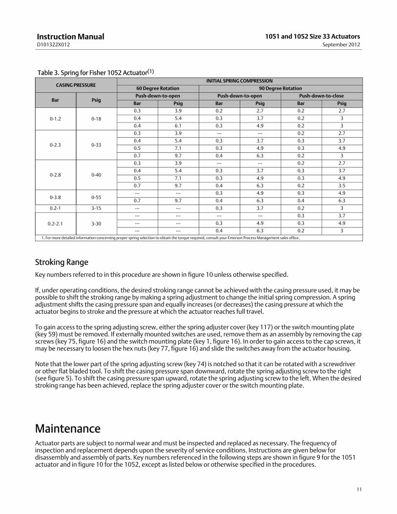
Table 3. Spring for Fisher 1052 Actuator(1)
CASING PRESSUREINITIAL SPRING COMPRESSION
60Degree Rotation 90 Degree Rotation
Bar PsigPush-down-to-open Push-down-to-open Push-down-to-close
Bar Psig Bar Psig Bar Psig
0-1.2 0-18
0.3 3.9 0.2 2.7 0.2 2.7
0.4 5.4 0.3 3.7 0.2 3
0.4 6.1 0.3 4.9 0.2 3
0-2.3 0-33
0.3 3.9 --- --- 0.2 2.7
0.4 5.4 0.3 3.7 0.3 3.7
0.5 7.1 0.3 4.9 0.3 4.9
0.7 9.7 0.4 6.3 0.2 3
0-2.8 0-40
0.3 3.9 --- --- 0.2 2.7
0.4 5.4 0.3 3.7 0.3 3.7
0.5 7.1 0.3 4.9 0.3 4.9
0.7 9.7 0.4 6.3 0.2 3.5
0-3.8 0-55--- --- 0.3 4.9 0.3 4.9
0.7 9.7 0.4 6.3 0.4 6.3
0.2-1 3-15 --- --- 0.3 3.7 0.2 3
0.2-2.1 3-30
--- --- --- --- 0.3 3.7
--- --- 0.3 4.9 0.3 4.9
--- --- 0.4 6.3 0.2 31. For more detailed information concerning proper spring selection to obtain the torque required, consult your Emerson Process Management sales office.
Stroking Range
Key numbers referred to in this procedure are shown in figure 10 unless otherwise specified.
If, under operating conditions, the desired stroking range cannot be achieved with the casing pressure used, it may bepossible to shift the stroking range bymaking a spring adjustment to change the initial spring compression. A springadjustment shifts the casing pressure span and equally increases (or decreases) the casing pressure at which theactuator begins to stroke and the pressure at which the actuator reaches full travel.
To gain access to the spring adjusting screw, either the spring adjuster cover (key 117) or the switchmounting plate(key 59) must be removed. If externally mounted switches are used, remove them as an assembly by removing the capscrews (key 75, figure 16) and the switchmounting plate (key 1, figure 16). In order to gain access to the cap screws, itmay be necessary to loosen the hex nuts (key 77, figure 16) and slide the switches away from the actuator housing.
Note that the lower part of the spring adjusting screw (key 74) is notched so that it can be rotated with a screwdriveror other flat bladed tool. To shift the casing pressure span downward, rotate the spring adjusting screw to the right(see figure 5). To shift the casing pressure span upward, rotate the spring adjusting screw to the left. When the desiredstroking range has been achieved, replace the spring adjuster cover or the switchmounting plate.
MaintenanceActuator parts are subject to normal wear andmust be inspected and replaced as necessary. The frequency ofinspection and replacement depends upon the severity of service conditions. Instructions are given below fordisassembly and assembly of parts. Key numbers referenced in the following steps are shown in figure 9 for the 1051actuator and in figure 10 for the 1052, except as listed below or otherwise specified in the procedures.
InstructionManualD101322X012
1051 and 1052 Size 33 ActuatorsSeptember 2012
12
Mounting Adaptations
F and G AdaptationsThe procedures given in this instructionmanual apply directly to F and Gmounting adaptations. Refer to figures 9 and10.
HMounting AdaptationsWhenever the procedures require separating the actuator from the operated equipment, it may be necessary toremove brackets, couplings, and stub shafts before proceeding. Refer to figure 11 for parts used with the Hmountingadaptation.
J Mounting AdaptationsWhenever the procedures require separating the actuator from the valve body, it may be necessary to removecouplings and keyways. Refer to figure 13 for parts used with the J mounting adaptation.
WARNING
Avoid personal injury or property damage from sudden release of process pressure or bursting of parts. Before performinganymaintenance operations:
D Do not remove the actuator from the valvewhile the valve is still pressurized.
D Always wear protective gloves, clothing, and eyewearwhen performing anymaintenance operations.
D Disconnect any operating lines providing air pressure, electric power, or a control signal to the actuator. Be sure theactuator cannot suddenly open or close the valve.
D Use bypass valves or completely shut off the process to isolate the valve from process pressure. Relieve process pressurefrom both sides of the valve. Drain the processmedia from both sides of the valve.
D Vent the power actuator loading pressure and relieve any actuator spring precompression.
D Use lock-out procedures to be sure that the abovemeasures stay in effect while youwork on the equipment.
D The valve packing boxmay contain process fluids that are pressurized, even when the valve has been removed from thepipeline. Process fluidsmay spray out under pressurewhen removing the packing hardware or packing rings.
D Checkwith your process or safety engineer for any hazards thatmay be present from exposure to process media.
Replacing Diaphragm
Disassembly1. Bypass the control valve. Relieve all loading pressure, and remove the tubing or pipe from the upper diaphragmcase (key 1).
2. Observe the position of the travel indicator pointer (key 37) andmark its position on the travel indicator scale(key 35).
WARNING
Failure to control spring tension against the upper diaphragm case as outlined in the following step could result in suddenspring decompression causing bodily injury or equipment damage. Control spring tension by following step 3 closely.
InstructionManualD101322X012
1051 and 1052 Size 33 ActuatorsSeptember 2012
13
3. Loosen the hex jam nut (key 84 for 1051, or key 86 for 1052) on the up travel stop. This stop is nearest to thepositioner or positioner cover (key 39; also see figure 3). Screw the travel stop in (turn it clockwise) until it can beverified that all spring tension has been removed from the diaphragm stop in the upper diaphragm case, i.e. whenanymovement of the travel indicator pointer is observed, all spring tension against the upper diaphragm case stophas been removed. Do not rotate the travel stop past this position as additional compression of the spring is notnecessary or desirable.
4. Carefully remove all cap screws and hex nuts (keys 5 and 6) from the diaphragm case.
5. Remove the diaphragm case and the diaphragm (key 3).
6. Inspect the diaphragm plate (key 4). If the diaphragm plate is damaged or if further disassembly of the actuator isrequired, proceed to the Diaphragm Plate, Diaphragm Rod, Spring, and Spring Seat procedure.
7. Inspect the diaphragm and replace if necessary.
Assembly1. Place the diaphragm (key 3) on the diaphragm plate (key 4), making certain that it is properly centered.
2. Make sure that the up travel stop (see figure 3) is screwed in sufficiently to eliminate interference of the diaphragmplate (key 4) with the upper diaphragm case.
3. Observe the correct position of the loading connection fitting and install the upper diaphragm case (key 1). Replacethe cap screws and nuts (keys 5 and 6) which secure the upper diaphragm case to the actuator housing. Tighten thenuts in an alternating fashion (see table 2).
CAUTION
When adjusting the travel stop for the closed position of the valve ball or disc, refer to the appropriate valve bodyinstructionmanual for detailed procedures. Undertravel or overtravel of many valve typesmay result in poor valveperformance and/or damage to the equipment.
4. Adjust the up travel stop (see figure 3). If the upper travel stop establishes the closed position of the valve ball ordisc, refer to the valve body instructionmanual and follow the procedures given for properly establishing the closedposition. Proceed as appropriate:
For F, G, and J mounting adaptations, perform operations beginning with step 8 under the appropriate mountingadaptation section of the Actuator Mounting and Changing Actuator Mounting procedure.
For Hmounting adaptations, perform operations beginning with step 7 under the appropriate mounting adaptationsection of the Actuator Mounting and Changing Actuator Mounting procedure.
5. Return the travel indicator pointer to its original position as previously marked on the travel indicator scale.
6. Install the inlet piping to the upper diaphragm case.
Replacing Diaphragm Plate, Diaphragm Rod, Spring, and Spring Set
Disassembly1. Perform steps 1 through 6 of the Disassembly portion of the Replacing Diaphragm procedure above.
For 1052 Actuators Only
a. Before removing the diaphragm plate, spring compressionmust be relieved. Proceed as appropriate to gainaccess to the spring adjusting screw:
InstructionManualD101322X012
1051 and 1052 Size 33 ActuatorsSeptember 2012
14
D Without lever-operated switches, remove the cap screws (key 21) and the spring adjuster cover (key 117).
D With lever-operated switches, remove the switches as an assembly by removing the cap screws (key 75, figure 16)and the switchmounting plate (key 1, figure 16). In order to gain access to the cap screws, it may be necessary toloosen the hex nuts (key 77, figure 16) and slide the switches away from the actuator housing.
WARNING
To avoid personal injury from precompressed spring force suddenly thrusting parts away from the actuator, springcompressionmust first be relieved by rotating the spring adjusting screw until the spring seat is bottomed against thespring adjuster. Closely follow the instructions below.
b. To relieve spring compression, insert a screwdriver into the notches on the spring adjusting screw and rotate thespring adjusting screw to the right (counter-clockwise when viewed from the top of the actuator) until the springseat (key 13) is bottomed against the spring adjuster.
2. For 1051 and 1052 Actuators, using a 5/16 inch hex wrench, unscrew and remove the socket head cap screw (key 9)which secures the diaphragm plate (key 4) to the diaphragm rod (key 10). Remove the diaphragm plate and theupper thrust washer (key 83 for 1051, or key 72 for 1052).
3. For the 1051, remove the spring (key 11) and spring seat (key 14).
For the 1052, remove the spring (key 11), spring seat with adjusting screw (keys 74 and 14), and lower thrust washer(key 72).
Note
At this stage of disassembly, it may be determined that further disassembly is not necessary. If separation of the diaphragm rodfrom the lever is not warranted, proceed to the Assembly portion of this procedure.
4. To gain access to the cap screw (key 18) which secures the diaphragm rod to the lever, the housing cover assembly(key 33) must be removed. Before the housing cover assembly can be removed, one of the following proceduresmust be performed. Proceed as appropriate:
For actuators with valve bodies mounted on the housing cover assembly (key 33) side of the actuator, the actuatormust be separated from the valve body to provide access to the cap screw (key 18). Proceed to the Disassemblyportion of the Changing or Replacing Actuator Lever procedure and perform steps 2 through 6.
For actuators with valve bodies mounted on the actuator housing boss side of the actuator, remove the travelindicator pointer (key 37).
5. Remove the cap screws andwashers (keys 34 and 63) and the housing cover assembly (key 33).
6. Remove the outer switch cam, if used, by removing the two hex headmachine screws, spacers, and retainingwashers (keys 119, 132, and 144, figures 15 and 16). Note that the retaining washers help to keep all parts togetheras an assembly.
7. Remove the cap screw (key 18) that secures the actuator lever (key 27) to the diaphragm rod. Remove thediaphragm rod.
8. Inspect all parts and replace if necessary.
9. If total disassembly of the actuator is required, or if the actuator will be assembled for use with a valve body with adifferent valve shaft diameter, proceed to the Changing or Replacing Actuator Lever procedure.
InstructionManualD101322X012
1051 and 1052 Size 33 ActuatorsSeptember 2012
15
SPRING NO.DIMENSION A
mm Inches
10B1522 42.7 1.68
10B1523 42.7 1.68
10B1524 42.7 1.68
10B1525 36.6 1.44
Figure 6. Spring Seat Pre-Set Dimensions for the Fisher 1052 Size 33 Actuator
10B1601-AA3777
A
Assembly
For the 1052 Only
a. Lubricate the threads of the spring adjusting screw (key 74) with lithium grease. Also lubricate the bottomportion of the spring adjusting screwwhich contacts the lower thrust washer (key 72).
b. Screw the spring adjusting screw onto the spring seat (key 14) tominimize spring seat adjustment afterassembly, refer to figure 6 and pre-set the spring adjusting screw to the appropriate dimension.
c. Place the lower thrust washer into the lower spring barrel area.
For 1051 and 1052
1. Lubricate the threads of the socket head cap screw (key 9) with lithium grease. Also lubricate the bottom surface ofthe diaphragm plate which contacts the upper thrust washer (key 83 for 1051, or key 72 for 1052).
2. Insert the socket head cap screw through the diaphragm plate (key 4) and into the diaphragm rod (key 10). Tightenthe cap screw four or five turns.
3. Install the spring seat (with spring adjusting screw for the 1052 actuator), spring, and upper thrust washer.
4. Insert the diaphragm plate/diaphragm rod assembly into the spring barrel. Make sure that the notch in thediaphragm rod is oriented according to the view shown in figures 9 and 10, i.e. the notch in the diaphragm rodmustface the positioner or positioner cover plate (key 39).
5. Rotate the lever so that it straddles the spherical bearing in the diaphragm rod. It may be necessary to exert lateralpressure on the diaphragm rod to achieve alignment of the rod with the lever. Install the cap screw (key 18) (seetable 2). Use the up travel stop (see figure 3) to keep the lever from rotating during tightening.
6. If the actuator uses an outer switch cam, install the outer cam (key 170, figures 15 and 16) using the two hex headmachine screws, spacers, and retaining washers (keys 119, 132, and 144). Note that the retaining washers help tokeep all parts together as an assembly to ease installation. Make sure that the cam is mounted on the leveraccording to the orientation shown in figure 7.
InstructionManualD101322X012
1051 and 1052 Size 33 ActuatorsSeptember 2012
16
Figure 7. Orientation of Switch and Positioner Cams on the Lever of the Fisher 1051 and 1052 Size 33 Actuator
7. Install the housing cover assembly (key 33) with cap screws andwashers (keys 34 and 63).8. Tighten the socket head cap screw (key 9) with a 5/16 hex wrench until the diaphragm plate is fully seated againstthe diaphragm rod. Tighten the cap screw to the torque value in table 2.
9. Perform steps 1 through 5 of the Assembly portion of the Replacing Diaphragm procedure.10. For 1052 actuators, refer to the 1052 Spring Compression Adjustment procedure and adjust the spring for thedesired initial set.
11. Install the cover plate or switchmounting plate (key 59) with cap screws (key 60). If switches are used, observe themarks made during removal of the cover plate.
12. Install the spring adjuster cover (key 117) or the switchmounting plate (key 1, figure 16) with the appropriate capscrews.
13. Install the travel indicator (key 37) if removed.14. If the actuator was removed from the valve body, refer to the appropriate section in the Actuator Mounting andChanging Actuator Mounting procedure and proceed as follows:
For F and Gmounting adaptations, perform all applicable steps beginning with step 3.
For H and J mounting adaptations, perform all applicable steps beginning with step 4.
Changing or Replacing Actuator Lever
NoteThe lever and associated parts may be removed as an independent procedure without disassembling the upper diaphragm casingor spring barrel components. Or, the lever may be removed after performing the operations given in the Replacing Diaphragmprocedure and in the Diaphragm Plate, Diaphragm Rod, Spring, and Spring Seat procedure.
InstructionManualD101322X012
1051 and 1052 Size 33 ActuatorsSeptember 2012
17
Disassembly
WARNING
Avoid personal injury or property damage from sudden release of process pressure or bursting of parts. Before performinganymaintenance operations:
D Do not remove the actuator from the valvewhile the valve is still pressurized.
D Always wear protective gloves, clothing, and eyewearwhen performing anymaintenance operations.
D Disconnect any operating lines providing air pressure, electric power, or a control signal to the actuator. Be sure theactuator cannot suddenly open or close the valve.
D Use bypass valves or completely shut off the process to isolate the valve from process pressure. Relieve process pressurefrom both sides of the valve. Drain the processmedia from both sides of the valve.
D Vent the power actuator loading pressure and relieve any actuator spring precompression.
D Use lock-out procedures to be sure that the abovemeasures stay in effect while youwork on the equipment.
D The valve packing boxmay contain process fluids that are pressurized, even when the valve has been removed from thepipeline. Process fluidsmay spray out under pressurewhen removing the packing hardware or packing rings.
D Checkwith your process or safety engineer for any other hazards thatmay be present from exposure to process media.
1. Isolate the valve body from the process. Release process pressure and vent all actuator pressure.
2. If externally mounted switches are used, remove them as an assembly by removing the cap screws (key 75, figure16) and the switchmounting plate (key 1, figure 16). In order to gain access to the cap screws, it may be necessaryto loosen the hex nuts (key 77, figure 16) and slide the switches away from the actuator housing.
3. If switches are used, mark the position of the switchmounting plate (key 59) on the actuator housing so it may bereturned to the exact same position.
4. Remove the cap screws (key 60) and the cover plate or switchmounting plate (key 59). If switches are used, leavethe push rod assemblies (keys 169 and 170, figure 16) or the proximity switch assemblies (key 7, figure 15)undisturbed.
5. Using a 5/16 inch hex wrench, loosen the socket head cap screw (key 28) which compresses the splined leverconnection around the valve shaft.
6. Separate the actuator from the valve body by removing the cap screws and washers which secure the valve to themounting yoke (key 22). For some constructions of H and J mounting adaptations, it may be necessary to removeother mounting and coupling parts.
7. If the valve body (or other operated equipment) is mounted on the housing cover (key 33) side of the actuator,remove themounting yoke and travel indicator pointer.
8. Remove the cap screws andwashers (keys 34 and 63) and the housing cover (key 33).
9. If the actuator is equipped with a positioner, remove the positioner cam (see figure 7) by removing the two hexheadmachine screws which secure the cam to the lever.
10. If the actuator is equipped with cam-operated switches, remove the outer cam (see figure 7) with the two hexheadmachine screws, spacers, and retaining washers (keys 119, 132, and 144, figures 15 and 16). Note that theretaining washers help to keep all parts together as an assembly.
WARNING
Failure to relieve spring tension on the diaphragm rod to lever connection before removing the cap screw (key 18)mayresult in personal injury and equipment damage from sudden and forceful movement of the diaphragm rod. Relieve springtension by performing the operations described in the next step.
InstructionManualD101322X012
1051 and 1052 Size 33 ActuatorsSeptember 2012
18
11. Relieve all spring loading on the diaphragm rod (key 10) to lever (key 27) connection by backing out (turningcounter-clockwise) the up position travel stop (see figure 3). When the travel stop is no longer in direct contact withthe lever (key 27), it can be determined that all spring compression is being contained by the stop in the upperdiaphragm case (key 1).
12. Remove the cap screw (key 18) which secures the diaphragm rod (key 10) to the lever (key 27). Disconnect thelever from the diaphragm rod by rotating the lever away from the diaphragm rod.
13. Remove and inspect the lever. If the lever is worn or damaged, or if the actuator will bemounted to a valve bodyrequiring a different size lever, replace the lever.
14. Inspect the bushings (key 31). If bushings are excessively worn or damaged, remove themwith a press. Press innew bushings so that they are flush with the interior surfaces of the actuator housing boss and housing coverassembly.
Assembly1. Refer to figure 7 for the correct orientation of the inner switch cam (if used); be sure that it is attached to the leverin the proper orientation.
2. Refer to figure 7 for the correct orientation of the lever during assembly. Insert the lever into the bushing in theactuator housing boss.
3. If the diaphragm rod has been removed, perform all operations through step 3 of the Assembly portion of theDiaphragm Plate, Diaphragm Rod, Spring and Spring Seat procedure.
4. Rotate the lever so that it straddles the spherical bearing in the diaphragm rod. It may be necessary to exert lateralpressure on the diaphragm rod to achieve alignment of the rod with the lever. Install the cap screw (key 18) andtighten to the torque value in table 2.
5. If an outer switch cam is used, install the cam using the twomachine screws, spacers, and retaining washers. Notethat the retaining washers help to keep all parts together as an assembly. Observe the orientation shown in figure 7.
6. If a positioner is used, install the positioner camwithmachine screws. Be sure to observe the orientation shown infigure 7 and follow all procedures given in the positioner instructionmanual.
7. Install the housing cover assembly (key 33).
8. If the diaphragm plate has been removed, tighten the socket head cap screw (key 9) with a 5/16 hex wrench untilthe diaphragm plate is fully seated against the diaphragm rod. Tighten the cap screw to the torque value in table 2.
9. If the upper diaphragm case has been removed, perform all applicable steps in the Assembly portion of theReplacing Diaphragm procedure.
10. Refer to the Actuator Mounting and Changing Actuator Mounting procedure and proceed as follows:
For F and Gmounting adaptations, start with step 3.
For H and J mounting adaptations, start with step 4.
11. For 1052 actuators only, refer to the 1052 Spring Compression Adjustment procedure and adjust the spring forthe desired initial set.
Proximity Switches, Lever Operated Switches, and PositionerThe proximity switches (see figure 15), lever operated switches (see figure 16), and positioner used with 1051 and1052 size 33 actuator use cams (see figure 7) mounted on the lever to transmit valve ball or disc position feedback tothe accessories. These camsmust be attached to the lever before accessories can be installed.
Installing the CamKey numbers referred to in the following procedures are shown in figure 15 for proximity switch installation and infigure 16 for lever operated switch installation unless otherwise specified. Proceed as appropriate:
InstructionManualD101322X012
1051 and 1052 Size 33 ActuatorsSeptember 2012
19
For switches which activate at the bottom of the actuator stroke, the inner cam (key 170; also see figure 7) is used.Installation of the inner cam requires removal of the actuator lever (key 27, figures 9 and 10). To remove the lever,refer to the Changing or Replacing Actuator Lever procedure and perform all applicable steps in the Disassemblyportion. Install the inner camwithmachine screws and retaining washers (keys 117 and 144). Note that the retainingwashers help to keep all parts together as an assembly to ease installation. Reassemble the actuator and install theactuator on the valve body.
For switches which activate at the top of the actuator stroke, the outer cam (key 170; also see figure 7) is used. If thevalve body or other operated equipment is mounted on the housing cover assembly side of the actuator, it will benecessary to remove the valve body and themounting yoke. Refer to the Changing or Replacing Actuator Leverprocedure and perform all applicable steps in the Disassembly portion. Remove the housing cover assembly (key 33).Install the outer camwithmachine screws, spacers, and retaining washers (keys 119, 132, and 144). Note that theretaining washers help to keep all parts together as an assembly to ease installation. Follow the steps in the Installationsection to reassemble the actuator and install the actuator on the valve body.
For actuators using a positioner, the positioner cam (see figure 7) must be installed on the lever. If the valve body orother operated equipment is mounted on the housing cover assembly side of the actuator, it will be necessary toremove the valve body and themounting yoke. Refer to the Changing or Replacing Actuator Lever procedure andperform all applicable steps in the Disassembly portion. Remove the housing cover assembly (key 33). Install the camon the lever withmachine screws in the orientation shown in figure 7 and in the positioner instructionmanual. Followthe steps in the Installation section to reassemble the actuator and install the actuator on the valve body.
Installing Proximity SwitchesKey numbers referenced in the following procedures are shown in figure 15 unless otherwise specified.
Switches Indicating Bottom of Stroke
1. Apply inlet pressure to the diaphragm case (key 1, figures 9 and 10) until the actuator is at the bottom of its stroke.Make sure that the lever (key 27, figures 9 and 10) is against the down position travel stop (see figure 3).
2. Install one 5/8 inch UNF jam nut (key 78) onto the proximity switch (key 7). Screw the switch assembly into themounting cover (key 59, figures 9 and 10) so that it is directly over the inner cam (refer to figure 3).
3. Carefully screw the switch into themounting cover until the electrical contacts close. Maintain aminimum of 0.5mm (0.02 inch) clearance between the switch and the cam.
4. Lock the switch in place by tightening the locknut (key 78) to the torque value in table 2. When tightening thelocknut, be careful not to turn the switch and thereby reduce its clearance with the cam.
Switches Indicating Top of Stroke
1. Make sure that the air supply to the diaphragm case (key 1, figures 9 and 10) is totally vented and the lever (key 27,figures 9 and 10) is against the up position travel stop (see figure 3).
2. Install one 5/8 inch UNF jam nut (key 78) onto the proximity switch (key 7). Screw the switch assembly into themounting cover (key 59, figures 9 and 10) so that it is directly over the outer cam (refer to figure 3).
3. Carefully screw the switch into themounting cover until the electrical contacts close. Maintain aminimum of 0.5mm (0.02 inch) clearance between the switch and the cam.
4. Lock the switch in place by tightening the locknut (key 78) to the torque value in table 2. When tightening thelocknut, be careful not to turn the switch and thereby reduce its clearance with the cam.
Installing Lever-Operated SwitchRefer to figure 16 for the key numbers referenced in the following procedures and for proper orientation of switchesand switchmounting accessories.
InstructionManualD101322X012
1051 and 1052 Size 33 ActuatorsSeptember 2012
20
Installing the Push Rod1. For Switches Indicating Bottom of Stroke, apply inlet pressure to the diaphragm case (key 1, figures 9 and 10) untilthe actuator is at the bottom of its stroke. Make sure that the lever (key 27, figures 9 and 10) is against the downposition travel stop (see figure 3).
For Switches Indicating Top of Stroke, make sure that the air supply to the diaphragm case (key 1, figures 9 and 10) istotally vented and the lever (key 27, figures 9 and 10) is against the up position travel stop (key 8, figures 9 and 10).
2. For Switches Indicating Bottom of Stroke, install one jam nut (key 78) onto the push rod guide (key 169). Refer tofigure 3 and screw the push rod guide into themounting cover (key 59, figures 9 and 10) so that it is directly overthe inner cam.
For Switches Indicating Top of Stroke, install one jam nut (key 78) onto the push rod guide (key 169). Screw the pushrod guide into themounting cover (key 59, figures 9 and 10) so that it is directly over the outer cam (refer to figure 3).
3. For both kinds of switches, insert the push rod (key 168) into the push rod guide with its head resting against theouter surface of the push rod guide.
4. Screw the push rod guide/push rod assembly in until the push rod contacts the cam (key 170).
5. Hold the push rod tightly against the push rod guide and screw the push rod guide into themounting cover until agap of 6.4 to 6.8mm (0.25 to 0.27 inch) exists between the push rod head and the surface of the push rod guide.
6. Lock the push rod guide in place by tightening the locknut to the torque value in table 2. Be careful not to turn thepush rod guide and thereby reduce its clearance with the push rod head.
7. Install the boot (key 163) over the push rod and the push rod guide.
Mounting Lever-Operated Switch and Adjustment1. If used, remove the cap screws and spring adjuster cover (keys 21 and 85 for 1051, or keys 21 and 117 for 1052).
2. Attach the switchmounting plate (key 1) at this location with cap screws (key 75). Tighten the cap screws to thetorque value in table 2.
3. Install the levers onto the switch shafts so that they are parallel to the centerline of the switch when they trip.
4. Insert the round head carriage bolts (key 4) into the switchmounting bracket (key 129). Mount the limit switchonto the bracket usingmachine screws and nuts (keys 8 and 9). Tighten themachine screws to 2.8 NSm (5 lbfSft).
5. Attach the switch/mounting bracket assembly to themounting plate using the nuts and washers (keys 77 and 154).
6. Adjust the switch lever on the shaft so that its roller is in the approximate center of the push rod.
7. With the actuator set at one end of its travel, slide the appropriate switch/bracket assembly toward the actuatoruntil the roller on the switch lever is in contact with the push rod head and the switch contacts close. Stroke theactuator to the opposite end of its travel and repeat the adjustment procedure for the other switch.
Positioner Mounting1. Before installing the positioner, the positioner cammust be installed on the lever (key 10, figures 9 and 10). Refer tothe Installing the Cam procedure.
2. Refer to the positioner instructionmanual for setup and calibration procedures.
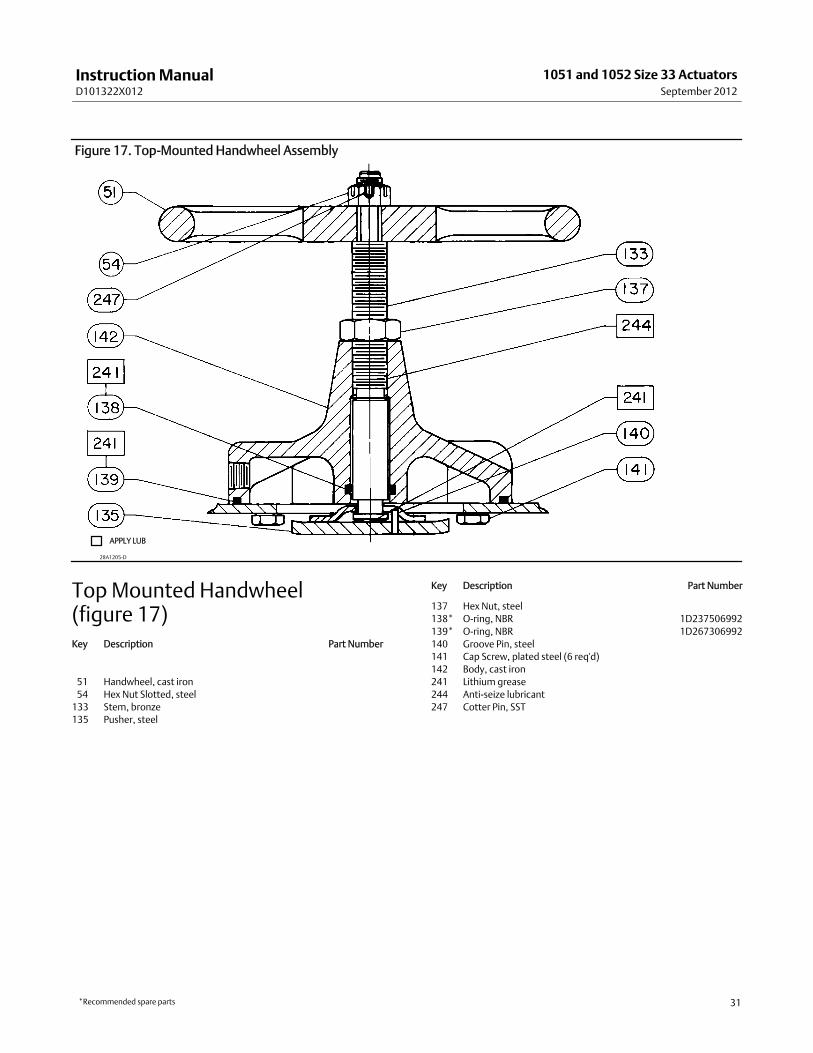
Top-Mounted HandwheelKey numbers used in this procedure are shown in figure 17 except where indicated.
The optional top-mounted handwheel can be used as amanual actuator for intermittent service or as an adjustable uptravel stop to limit full retraction of the diaphragm rod (key 10, figures 9 and 10).
InstructionManualD101322X012
1051 and 1052 Size 33 ActuatorsSeptember 2012
21
The handwheel assembly is attached to a special upper diaphragm casing (key 1, figures 9 and 10) with cap screws(key 141). A hex nut (key 137) locks the handwheel in position. For field installation of a handwheel, the special upperdiaphragm casemust be ordered as well as the handwheel.
Turning the handwheel (key 51) clockwise into the upper casing forces the pusher plate (key 135) against thediaphragm and diaphragm plate (keys 3 and 4) to compress the spring (key 11, figures 9 and 10) andmove thediaphragm rod downward. Turning the handwheel counter-clockwise allows the actuator spring tomove thediaphragm rod upward. If the valve is push-down-to-close, full opening can be restricted by positioning the handwheelat the desired position. If the valve is push-down-to-open, full closing of the valve ball or disc can be restricted by useof the handwheel.
Instructions are given below for complete disassembly and assembly required for inspection and parts replacement.
Disassembly
WARNING
To avoid personal injury from the precompressed spring force thrusting the upper diaphragm casing away from theactuator, relieve spring compression before diaphragm casing bolting is loosened.
1. Remove the upper diaphragm casing (key 1, figures 9 and 10) by following steps 1 through 5 of the disassemblyportion of the Replacing Diaphragm procedure.
2. Remove the cotter pin, hex nut, handwheel, and locknut (keys 247, 54, 51, and 137). Unscrew the stem (key 133)out through the actuator end of the handwheel body (key 142).
3. Remove cap screws (key 141), and separate the handwheel assembly from the upper casing.4. Check the condition of the O-rings (keys 138 and 139); replace them if necessary.5. If it is necessary to remove the pusher plate or spacer (key 135 or 171), drive out the groove pin (key 140).
Assembly1. Before assembling, lubricate the thread of the stem (key 133) with anti-seize lubricant (key 244). Lubricate thebearing surfaces of the stem and pusher plate (key 135) with lithium grease (key 241).
2. If the pusher plate or spacer was removed, attach them to the stem and drive in a new groove pin (key 140).3. With the O-ring (key 138) in place, thread the stem into the handwheel assembly.4. Attach the handwheel assembly to the upper diaphragm casing (key 1, figures 9 and 10) with cap screws (key 141).5. Install the locknut, handwheel, hex nut, and cotter pin (keys 137, 51, 54, and 247).6. Install the diaphragm casing, making certain the warning tag is in place on the casing flange.7. Tighten the cap screws (key 5, figures 9 and 10) evenly in a crisscross pattern (see table 2).8. Adjust the initial set as described in the Spring Compression Adjustment procedure.
LockingMechanism
Installing the Locking Mechanism
WARNING
To avoid personal injury, perform the steps in theWARNING at the beginning of theMaintenance section to isolate thecontrol valve and actuator.
InstructionManualD101322X012
1051 and 1052 Size 33 ActuatorsSeptember 2012
22
Figure 8. Fisher 1051 and 1052 Actuator Locking Mechanism
24B0391-AA6226
CAP SCREW(KEY 21)
MOUNTING PLATEASSEMBLY (KEY 124)
COVER(KEY 59)
JAMNUT(KEY 128)
MOUNTING PLATE(KEY 123)
PADLOCK(CUSTOMER SUPPLIED)
CAP SCREW(KEY 60)
GROOVE PIN(KEY 127)
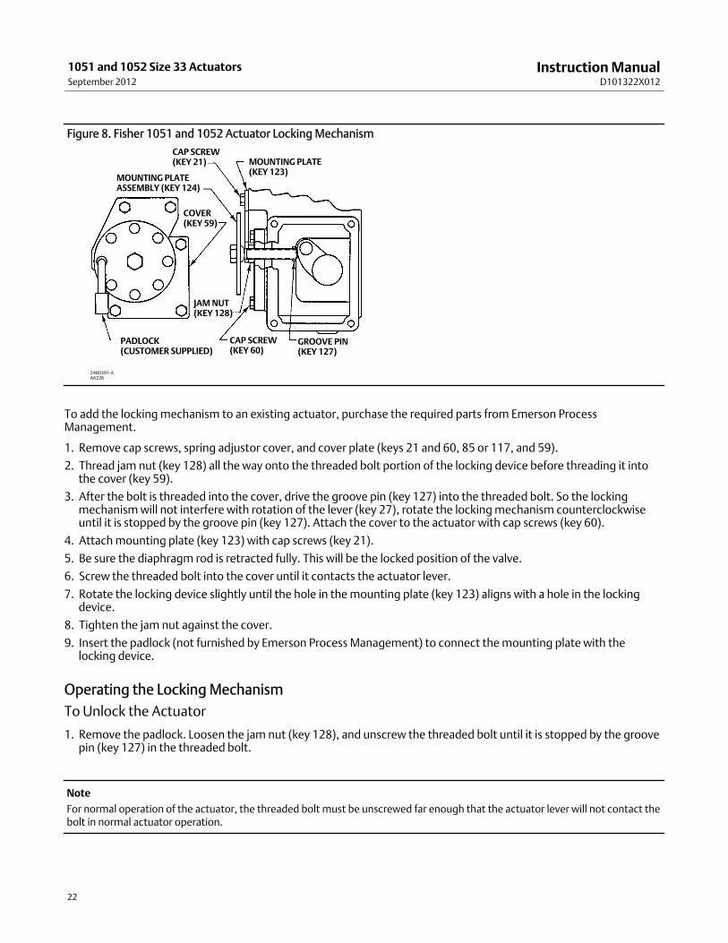
To add the lockingmechanism to an existing actuator, purchase the required parts from Emerson ProcessManagement.
1. Remove cap screws, spring adjustor cover, and cover plate (keys 21 and 60, 85 or 117, and 59).
2. Thread jam nut (key 128) all the way onto the threaded bolt portion of the locking device before threading it intothe cover (key 59).
3. After the bolt is threaded into the cover, drive the groove pin (key 127) into the threaded bolt. So the lockingmechanismwill not interfere with rotation of the lever (key 27), rotate the lockingmechanism counterclockwiseuntil it is stopped by the groove pin (key 127). Attach the cover to the actuator with cap screws (key 60).
4. Attachmounting plate (key 123) with cap screws (key 21).
5. Be sure the diaphragm rod is retracted fully. This will be the locked position of the valve.
6. Screw the threaded bolt into the cover until it contacts the actuator lever.
7. Rotate the locking device slightly until the hole in themounting plate (key 123) aligns with a hole in the lockingdevice.
8. Tighten the jam nut against the cover.
9. Insert the padlock (not furnished by Emerson Process Management) to connect themounting plate with thelocking device.
Operating the Locking MechanismTo Unlock the Actuator
1. Remove the padlock. Loosen the jam nut (key 128), and unscrew the threaded bolt until it is stopped by the groovepin (key 127) in the threaded bolt.
Note
For normal operation of the actuator, the threaded bolt must be unscrewed far enough that the actuator lever will not contact thebolt in normal actuator operation.
InstructionManualD101322X012
1051 and 1052 Size 33 ActuatorsSeptember 2012
23
2. If you are going to leave the bolt threaded into the cover, lock it with the jam nut (key 128) so that it cannot bescrewed into the cover and interfere with normal actuator operation.
To Lock the Actuator
1. Make sure the actuator diaphragm rod is retracted fully (the locked position of the valve). For a push-down-to-closevalve and actuator, the valve will be fully open when locked. For a push-down-to-open valve and actuator, the valvewill be fully closed when locked.
2. Make sure the jam nut (key 128) is loose. Then, screw the threaded bolt into the cover until it contacts the actuatorlever.
3. Rotate the threaded bolt until one of the holes in the locking disc (which is welded to the bolt) is in line with thehole in themounting plate (key 123). Tighten the jam nut against the cover.
4. Lock the plate and disc together with a padlock (not furnished by Emerson Process Management).
Parts OrderingWhen corresponding with your Emerson Process Management sales office about this equipment, refer to the serialnumber found on the actuator nameplate.
WARNING
Use only genuine Fisher replacement parts. Components that are not supplied by Emerson Process Management shouldnot, under any circumstances, be used in any Fisher valve, because theymay void your warranty, might adversely affect theperformance of the valve, and could cause personal injury and property damage.
Parts KitsKey Description Part Number
Retrofit KitsKit provides parts to add a top-mounted handwheel.Kit number 1 includes the handwheel assembly only.Kit number 2 includes Kit number 1 and a new UpperCase (key 1) required tomount the handwheel assembly.Kit Number 1 28A1205X082Kit Number 2 28A1205X092
Parts List
Note
Part numbers are shown for recommended spares only. For partnumbers not shown, contact your Emerson Process Management salesoffice.
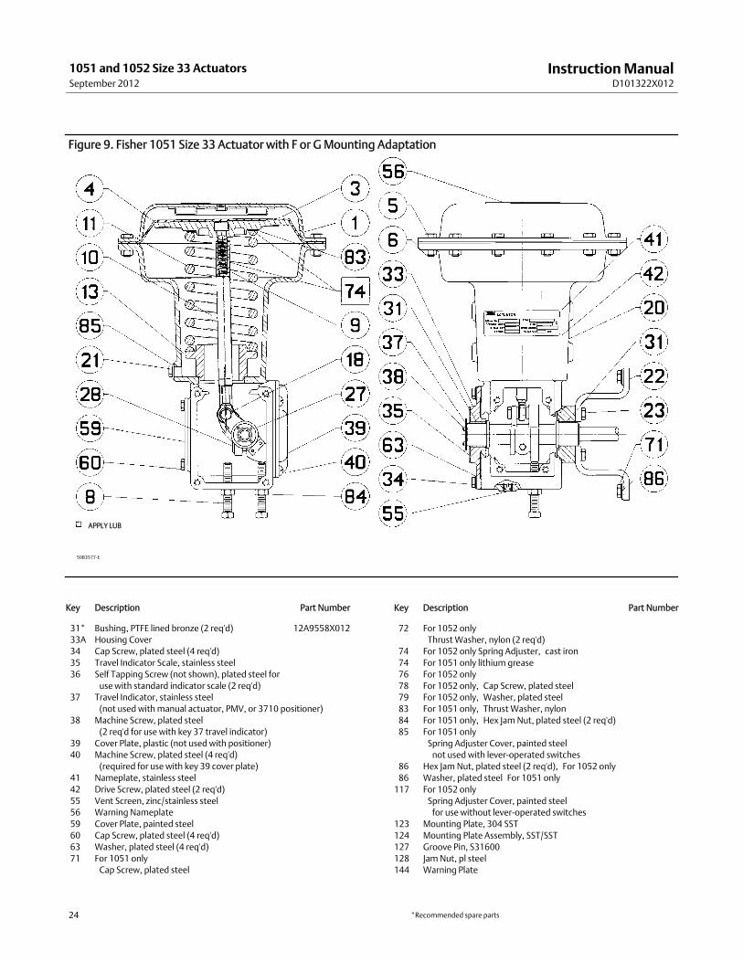
Basic ActuatorWith F and GMounting Adaptations (figures 9and 10)Key Description Part Number
use with standard indicator scale (2 req'd)37 Travel Indicator, stainless steel
(not used withmanual actuator, PMV, or 3710 positioner)38 Machine Screw, plated steel
(2 req'd for use with key 37 travel indicator)39 Cover Plate, plastic (not used with positioner)40 Machine Screw, plated steel (4 req'd)
(required for use with key 39 cover plate)41 Nameplate, stainless steel42 Drive Screw, plated steel (2 req'd)55 Vent Screen, zinc/stainless steel56 Warning Nameplate59 Cover Plate, painted steel60 Cap Screw, plated steel (4 req'd)63 Washer, plated steel (4 req'd)71 For 1051 only
Cap Screw, plated steel
Key Description Part Number
72 For 1052 onlyThrustWasher, nylon (2 req'd)
74 For 1052 only Spring Adjuster, cast iron74 For 1051 only lithium grease76 For 1052 only78 For 1052 only, Cap Screw, plated steel79 For 1052 only, Washer, plated steel83 For 1051 only, ThrustWasher, nylon84 For 1051 only, Hex JamNut, plated steel (2 req'd)85 For 1051 only
Spring Adjuster Cover, painted steelnot used with lever-operated switches
86 Hex Jam Nut, plated steel (2 req'd), For 1052 only86 Washer, plated steel For 1051 only117 For 1052 only
Spring Adjuster Cover, painted steelfor use without lever-operated switches
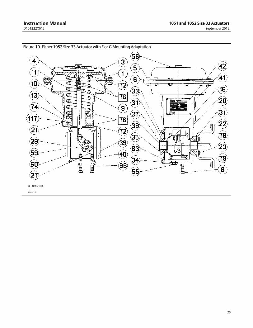
Figure 10. Fisher 1052 Size 33 Actuator with F or GMounting Adaptation
50B3571-F
APPLY LUB
InstructionManualD101322X012
1051 and 1052 Size 33 ActuatorsSeptember 2012
26
Figure 11. Parts Used for the HMounting Adaptation
50B1581-CA3780-1
NOTE:REQUIRES APPROPRIATE LEVER (KEY 27) FOR HMOUNTING ADAPTATION - SEE PARTS LIST.
2. STYLE AMOUNTING SHOWN. FOR STYLE B, ASSEMBLE PARTS LISTED AND TRAVEL INDICATOR COMPONENTS ON OPPOSITE ENDS OF LEVER.1
1051KEY
1052KEY
Figure 12. Standard and Reverse Constructions of the Stub Shaft Used for HMounting Adaptations
50B1581-B
STANDARDCONSTRUCTION
REVERSECONSTRUCTION
Parts Used For HMountingAdaptations (figure 11)Key Description
Parts For UseWith 1051 Actuators Only77 Stub Shaft, steel (1 req'd for valve mounting: 2 req'd for use
with manual actuator or wrench-operated extension)79 Pin, steel (1 req'd for each stub shaft)Parts For UseWith 1052 Actuators Only87 Stub Shaft, steel (1 req'd for valve
mounting; 2 req'd for use with manualactuator or wrench-operated extension)
89 Pin, steel (1 req'd for each stub shaft)
InstructionManualD101322X012
1051 and 1052 Size 33 ActuatorsSeptember 2012
27
Figure 13. Parts Used for the J Mounting Adaptation
50B1584-CA3781-1
NOTE:REQUIRES APPROPRIATE LEVER (KEY 27) FOR J MOUNTING ADAPTATION - SEE PARTS LIST.
2. STYLE AMOUNTING SHOWN. FOR STYLE B, ASSEMBLE PARTS LISTED AND TRAVEL INDICATOR COMPONENTS ONOPPOSITE ENDS OF LEVER.1
1051KEY
1052KEY
Parts Used For J MountingAdaptations (figure 13)Key Description Part Number
Parts For UseWith 1051 Actuators Only44 Pin, steel (for coupler)79 Pin, steel (for stub shaft)80 Coupling, steel81* Woodruff key, steel
For 3/8, 1/2 inch valve shaft size F13576X0062For 5/8 inch valve shaft size F13577X0052
For 3/8, 1/2 inch valve shaft size F13576X0062For 5/8 inch valve shaft size F13577X0052
119 Pin, steel (for coupler)120 Stub shaft, steel
*Recommended spare parts
InstructionManualD101322X012
1051 and 1052 Size 33 ActuatorsSeptember 2012
28
Figure 14. Parts Used forWrench-Operated Extension andManual Actuator Installation on All Mounting Adaptations
50B1588-CA3779-2
PARTS USEDFORWRENCH-OPERATED EXTENSION
PARTS USED FORINSTALLATIONOFMANUAL ACTUATOR
1051KEY
1052KEY
1051KEY
1052KEY
NOTE:PART NOT USED; KEY 38, FIGURES 8 AND 9.REQUIRES USE OF APPROPRIATE LEVER (KEY 27) - SEE PARTS LIST.NO TRAVEL INDICATOR COMPONENTS USED (KEYS 35, 36, 37, AND 38 FIGURES 8 AND 9).
123
2
2
1
3
Parts Used ForWrench-OperatedExtension and For ManualActuator Installation On AllMounting Adaptations (figure 14)Key Description
37 Travel Indicator, stainless steel(not used withmanual actuator)
Parts For UseWith 1051 Actuators Only77 Stub shaft, steel78 Retaining Ring, steel, for use with
travel indicator (key 37) above only79 Pin, steelParts For UseWith 1052 Actuators Only87 Stub shaft, steel88 Retaining Ring, steel, for use with
travel indicator (key 37) above only89 Pin, steel
InstructionManualD101322X012
1051 and 1052 Size 33 ActuatorsSeptember 2012
29
Figure 15. Proximity SwitchMounting on the Fisher 1051 and 1052 Size 33 Actuator
Emerson Process ManagementMarshalltown, Iowa 50158 USASorocaba, 18087 BrazilChatham, Kent ME4 4QZUKDubai, United Arab EmiratesSingapore 128461 Singapore
www.Fisher.com
The contents of this publication are presented for informational purposes only, and while every effort has beenmade to ensure their accuracy, they are notto be construed as warranties or guarantees, express or implied, regarding the products or services described herein or their use or applicability. All sales aregoverned by our terms and conditions, which are available upon request. We reserve the right tomodify or improve the designs or specifications of suchproducts at any time without notice.
E 1986, 2012 Fisher Controls International LLC. All rights reserved.
Fisher, FIELDVUE, Vee-Ball, and FISHTAIL aremarks owned by one of the companies in the Emerson Process Management business unit of Emerson ElectricCo. Emerson Process Management, Emerson, and the Emerson logo are trademarks and servicemarks of Emerson Electric Co. All other marks are theproperty of their respective owners.
Neither Emerson, Emerson Process Management, nor any of their affiliated entities assumes responsibility for the selection, use ormaintenanceof any product. Responsibility for proper selection, use, andmaintenance of any product remains solely with the purchaser and end user.