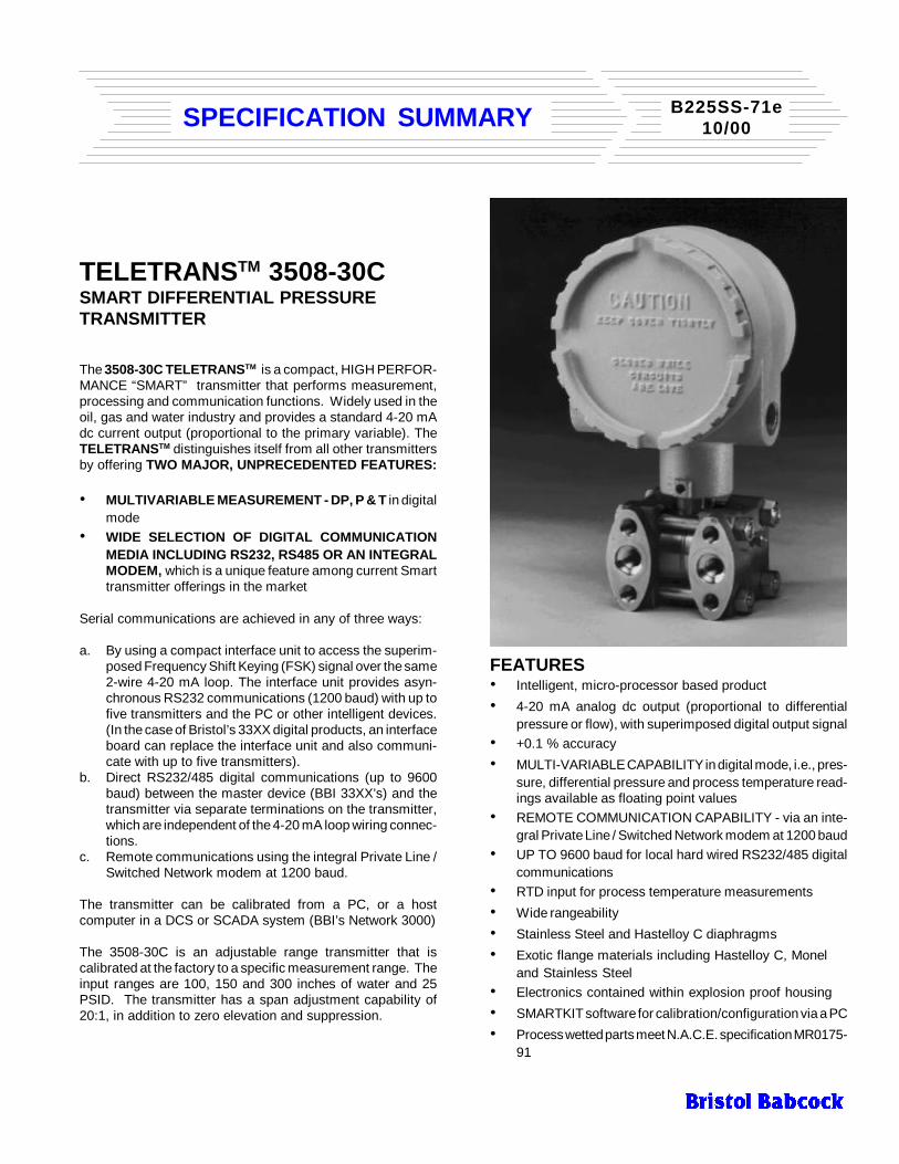
TELETRANS TM 3508-30C SMART DIFFERENTIAL PRESSURE TRANSMITTER The 3508-30C TELETRANS TM is a compact, HIGH PERFOR- MANCE “SMART” transmitter that performs measurement, processing and communication functions. Widely used in the oil, gas and water industry and provides a standard 4-20 mA dc current output (proportional to the primary variable). The TELETRANS TM distinguishes itself from all other transmitters by offering TWO MAJOR, UNPRECEDENTED FEATURES: • MULTIVARIABLE MEASUREMENT - DP, P & T in digital mode • WIDE SELECTION OF DIGITAL COMMUNICATION MEDIA INCLUDING RS232, RS485 OR AN INTEGRAL MODEM, which is a unique feature among current Smart transmitter offerings in the market Serial communications are achieved in any of three ways: a. By using a compact interface unit to access the superim- posed Frequency Shift Keying (FSK) signal over the same 2-wire 4-20 mA loop. The interface unit provides asyn- chronous RS232 communications (1200 baud) with up to five transmitters and the PC or other intelligent devices. (In the case of Bristol’s 33XX digital products, an interface board can replace the interface unit and also communi- cate with up to five transmitters). b. Direct RS232/485 digital communications (up to 9600 baud) between the master device (BBI 33XX’s) and the transmitter via separate terminations on the transmitter, which are independent of the 4-20 mA loop wiring connec- tions. c. Remote communications using the integral Private Line / Switched Network modem at 1200 baud. The transmitter can be calibrated from a PC, or a host computer in a DCS or SCADA system (BBI’s Network 3000) The 3508-30C is an adjustable range transmitter that is calibrated at the factory to a specific measurement range. The input ranges are 100, 150 and 300 inches of water and 25 PSID. The transmitter has a span adjustment capability of 20:1, in addition to zero elevation and suppression. FEATURES • Intelligent, micro-processor based product • 4-20 mA analog dc output (proportional to differential pressure or flow), with superimposed digital output signal • +0.1 % accuracy • MULTI-VARIABLE CAPABILITY in digital mode, i.e., pres- sure, differential pressure and process temperature read- ings available as floating point values • REMOTE COMMUNICATION CAPABILITY - via an inte- gral Private Line / Switched Network modem at 1200 baud • UP TO 9600 baud for local hard wired RS232/485 digital communications • RTD input for process temperature measurements • Wide rangeability • Stainless Steel and Hastelloy C diaphragms • Exotic flange materials including Hastelloy C, Monel and Stainless Steel • Electronics contained within explosion proof housing • SMARTKIT software for calibration/configuration via a PC • Process wetted parts meet N.A.C.E. specification MR0175- 91 B225SS-71e 10/00 SPECIFICATION SUMMARY
The 3508-30C TELETRANSTM is a compact, HIGH PERFOR-MANCE “SMART” transmitter that performs measurement,processing and communication functions. Widely used in theoil, gas and water industry and provides a standard 4-20 mAdc current output (proportional to the primary variable). TheTELETRANSTM distinguishes itself from all other transmittersby offering TWO MAJOR, UNPRECEDENTED FEATURES:
• MULTIVARIABLE MEASUREMENT - DP, P & T in digitalmode
• WIDE SELECTION OF DIGITAL COMMUNICATIONMEDIA INCLUDING RS232, RS485 OR AN INTEGRALMODEM, which is a unique feature among current Smarttransmitter offerings in the market
Serial communications are achieved in any of three ways:
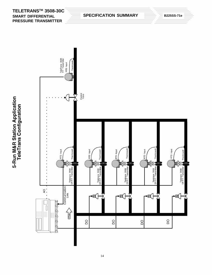
a. By using a compact interface unit to access the superim-posed Frequency Shift Keying (FSK) signal over the same2-wire 4-20 mA loop. The interface unit provides asyn-chronous RS232 communications (1200 baud) with up tofive transmitters and the PC or other intelligent devices.(In the case of Bristol’s 33XX digital products, an interfaceboard can replace the interface unit and also communi-cate with up to five transmitters).
b. Direct RS232/485 digital communications (up to 9600baud) between the master device (BBI 33XX’s) and thetransmitter via separate terminations on the transmitter,which are independent of the 4-20 mA loop wiring connec-tions.
c. Remote communications using the integral Private Line /Switched Network modem at 1200 baud.
The transmitter can be calibrated from a PC, or a hostcomputer in a DCS or SCADA system (BBI’s Network 3000)
The 3508-30C is an adjustable range transmitter that iscalibrated at the factory to a specific measurement range. Theinput ranges are 100, 150 and 300 inches of water and 25PSID. The transmitter has a span adjustment capability of20:1, in addition to zero elevation and suppression.
FEATURES• Intelligent, micro-processor based product• 4-20 mA analog dc output (proportional to differential
pressure or flow), with superimposed digital output signal• +0.1 % accuracy• MULTI-VARIABLE CAPABILITY in digital mode, i.e., pres-
sure, differential pressure and process temperature read-ings available as floating point values
• REMOTE COMMUNICATION CAPABILITY - via an inte-gral Private Line / Switched Network modem at 1200 baud
• UP TO 9600 baud for local hard wired RS232/485 digitalcommunications
• RTD input for process temperature measurements• Wide rangeability• Stainless Steel and Hastelloy C diaphragms• Exotic flange materials including Hastelloy C, Monel
and Stainless Steel• Electronics contained within explosion proof housing• SMARTKIT software for calibration/configuration via a PC• Process wetted parts meet N.A.C.E. specification MR0175-
• Reduced susceptibility to pulsation• Improved reliability due to Surface Mount Technology
(SMT)• Increased recommended RTD lead length (100 ft.)• Improved noise reduction• Greater communication signal integrity at lower voltages• Lower voltage requirements when operating in digital
mode allowing interface with 12V nominal systems whenused with Bristol Babcock Low Power TIB assembly
OPTIONS
• Choice of 9-14/22-28 V supply with RS232/485/modemcommunication options
• Metameter Pulse Duration Output (PDO)• Integral digital LCD meter, in linear or engineering units
BENEFITS
• MAJOR installation and product cost savings, in terms ofthe transmitter’s MULTIVARIABLE CAPABILITY, i.e. thistransmitter eliminates the need for separate pressure,differential pressure and temperature transmitters to beinstalled for a given application, by virtue of its multivari-able output (P, DP, T) in digital mode
• TWO-YEAR WARRANTY, covering Service and Repair• Easily configured through a Personal Computer, or from
a “Host” computer in a Distributed Control System (DCS)or SCADA System.
• Automatic temperature and static pressure compensa-tion, resulting in consistent accuracy over the specifiedambient temperature and operating pressure ranges
• LOW POWER requirements when operating in digitalmode
• Lower wiring cost and ease of installation when utilizingremote capability
• Digital communications link between 3508-30CTELETRANSTM and Bristol’s 33XX products
THEORY OF OPERATION
The differential pressure and static pressure measurementsare performed by a dual strain gauge circuit. Both sensorsconsist of an internal silicon diaphragm into which piezoresistivestrain gauge resistors are diffused, then interconnected to
form a pressure sensitive Wheatstone Bridge. The two outerprocess diaphragms (Hi and Lo sides) are hydraulically con-nected to the DP sensor using a suitable fill fluid. The staticpressure strain gauge is contained in the Hi side of the DP fluidsystem to sense upstream process measurements.
Both bridges are powered by a precision current source, andboth develop millivolt signals that correspond to the inputs (DPand P) at the outer process diaphragms. Both analog outputsare converted to equivalent digital data via a multiplexer(MUX), a differential amplifier and a voltage count converter.The data is then read by the microprocessor (MP), whichperforms data acquisition, data processing and decision func-tions of the transmitter. The MP then converts the digital DPvalue back to an analog signal via a digital to analog converter(DAC), hence providing the standard 4 - 20 mA dc outputsignal.
When the RS232, RS485, or modem options are present, thedefault serial communications path is set for the particularoption selected. If local FSK communications are detected(using the 1200 baud transmitter interface unit), the MUXswitches over to accommodate it on the serial port, andremains local for a time out period. Switching between localFSK and optional communications is automatic - one secondafter the last communications via FSK, the 3508 will beginlistening to the option selected.
All the circuitry for options (RS232, RS485 and modem)resides on an interface board sandwiched between the digitalboard and the customer termination plate.
The transmitter can function with a 9-14/22-28 V supplysource, based on options selected. The electronics alsoinclude a power fail detector that prevents the transmitter fromoperating when the applied power is below specifications.
ACCESSORIES AND OPTIONS
RTD Input: The transmitter contains screw terminations on theterminal block for input from an external RTD bulb. The RTDprobe (2 or 3 wire, DIN 43760) is typically mounted in a processpipe so that it is in contact with the measured media. The bulbs,which are offered with probes of varying lengths, may be smallor large head types. Measurements are presented as digitalvalues via the serial communication channel.
Metameter PDO: The transmitter provides a nonpolar opto-isolated Pulse Duration Output (PDO), which corresponds tothe instantaneous value (0 to 100%) of the 4-20 mA output.The PDO signal can be configured to transmit any pulse periodup to 120 seconds, and is akin to the pulse duration modulatedsignal from a Bristol metameter. Again, screw terminations areavailable for this option.
SMARTKIT: The SMARTKIT Software program functions as
the operator - to - transmitter interface. This software (availableon a 3-1/2" disk) allows the operator to calibrate the transmitter,select a forward or reverse acting output, change ranges,select damping coefficients, select a linear or square rootoutput, configure the RS232/485 and modem options, andread or write data. All digital signals such as pressure,differential pressure, RTD temperature, bridge sensor tem-perature, error flags, etc., are communicated via the SMARTKITprogram. SMARTKIT can be run on an IBM compatible PC.
Transmitter Interface Unit (TIU): A special Bristol BabcockInterface unit provides an RS232 interface for FSK communi-cation. The interface unit provides a nine pin female Dconnector that accepts the RS232 interface from the PC, andreceives power from drivers in the PC. Serial communicationsare at 1200 baud in the Bristol Standard Asynchronous/Syn-chronous Protocol (BSAP).
Transmitter Interface Board (TIB): For communications witha DPC 3330/3335/RTU 3310, an interface board can be usedas an alternative to the interface unit. The interface board ishoused piggy back on the communications board of a DPC3330 or RTU 3310, or in the option slot of a DPC 3335, and canaccommodate up to 5 transmitters in a multi-drop loop ar-rangement using FSK communications. Polling speed is onetransmitter per second. The interface board arrangementdoes not require any separate power source, as it draws powerfrom the master device.
The interface board allows the transmitter to function as a localnode, network node (end device), or as a slave to a masterdevice (BBI’s Distributed Process Controller 3330/3335/RTU3310).Reference Specification Summary D461SS-6
Note: For sole transmitter applications, the output current canbe fixed at 3.8 mA (via SMARTKIT) when only FSK or PDO arerequired. For multi-transmitter applications, this mode is arequirement.
Bristol Babcock Transmitter Interface (BBTI): Allows up toeight transmitters to be connected to a 33XX controller (RTU3310, DPC 3330 and DPC 3335) process I/O card. The BBTIphysically occupies one of the 33XX controller I/O slots andconnects to a DIN rail mountable field termination module viaa ribbon cable.
Communication occurs at 1200 bps for each transmitter.Simultaneous, independent communication to up to eighttransmitters is supported allowing floating point data for alltransmitters to be refreshed in less than one second. A BBTIACCOL software module is provided in the 33XX firmware.Reference Specification Summary D456SS-6
Low Power Transmitter Interface Board (LPTIB): Providesterminations for two 3508 transmitters with communications at1200 bps. “Fast” polling for two transmitters can occur at a
one-second interval. The LPTIB will bracket-mount in a TeleFlowPlus or TeleRTU Plus enclosure. The Stand-alone LPTIB usesa cable harness assembly to interface with the serial port on anI/O expansion board. Reference product information packagePIP-TIBS3530.
Expansion Transmitter Interface Board (ExpTIB): Equiva-lent to the LPTIB. The ExpTIB mounts directly to the TeleFlowPlus or TeleRTU Plus CPU board. Reference product informa-tion package PIP-ETIBS.
RS232 Interface: Provides point-to-point communications(using BSAP) from the transmitter to the master device (BBI33XX). Baud rates are selectable using SMARTKIT - 1200,2400, 4800, and 9600 baud are offered. Distance for hard-wired slaves from the master should not exceed 50 feet. TheRS232 output can also be connected to other devices such asa radio.
RS485 Interface: Provides 4-wire, multi-drop communica-tions between the master and slaves within the network - up to32 transmitters can be accommodated off a communicationsport at the master (BBI’s 33XX). Again, the same options forbaud rates (up to 9600 baud) are offered, as is with the RS232interface. Wiring length should not exceed 1000 feet.
Modem: Provides asynchronous, 2 or 4-wire private line, 2-wire switched network communications. Configurations pos-sible are: Point-to-point (one-to-one) and multi-drop (up to 5transmitters for 2-wire, 20 for 4-wire). 4-wire networks arealways preferable, as they provide better noise immunity than2-wire networks. Baud rate is set at 1200 for all these options.
SPECIFICATION FOR TRANSMITTER:
FUNCTIONAL SPECIFICATIONS
Differential & Static Pressure System
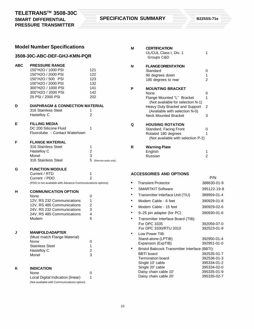
Model Diff. PressureSuffix Ranges Static Lower UpperABC (Max. Span) Pressure Range Limit Range Limit121 150 in. H2O 1000 psig -150 in H2O 150 in. H2O122 150 in. H2O 2000 psig -150 in H2O 150 in. H2O123 150 in. H2O 500 psig -150 in. H2O 150 in. H2O132 100 in. H2O 2000 psig -100 in. H2O 100 in. H2O141 300 in. H2O 1000 psig -300 in. H2O 300 in. H2O142 300 in. H2O 2000 psig -300 in. H2O 300 in. H2O202 25 PSID 2000 psig -25 PSID 25 PSID
Overpressure Limit: To full static rating on either side
• Physical:RTD input requires DIN 43760 Platinum Resistance BulbProvides 1/2" NPT port for direct sensor mounting orconduit connection.Recommended maximum lead length is 100 feet. Isola-tion limited to that provided by bulb.
• Input Temperature Range:-58 to 842° F (-50 to 450°C)
Internal Temperature Sensor
• Function:Provides temperature compensation for measurementcircuit.
• Operating Range:-40 to 185° F (-40 to 85° C)
Analog Output
• Linear Mode:4-20 mA for 0-100% of calibrated spanCurrent Limited: 22 mA max. 3.8 mA min.
• Square Root Mode:Output clamped at 4 mA for zero and negative pressures.For pressures between 0 and .8%, output is linear. Forpressures between 0.8% and 1% of URL, value is linearif entered from below, square root if entered from above.From 1% to 100%, output is square root. Above 100%output is linear.
• Reversible Output Action:For forward action, current increases with increase ofpressure. For reverse action, current decreases with anincrease of pressure.
• Fixed Current Output Mode:The 4-20 mA output may be fixed at 3.8 mA when only theFSK or PDO communications are required.
• The output current may be externally controlled via serialcommunications to provide a remote AO.
• Turndown Ratio: from 1:1 to 20:1• Resolution: .03% for turndowns between 1:1 and 7:1,
.03% x (ratio/7) for turndowns greater than 7:1
Pulse Duration Output (PDO)
• PDO Tracking:PDO tracks differential pressure via 4-20 mA output.
• Maximum Pulse Period:120 seconds. Standard PDO ranges are listed below. Thestandard ranges are selectable in SMARTKIT.
• Current Loop:Open collector, opto-isolated output. Maximum open loopsupply voltage is 200 V; maximum closed loop current is100 mA.
PDO Standard Periods
Period in Span inSeconds* Seconds I.R.E.**
15 0 to 13.33 .13%15 3 to 12 .18%8 0 to 7.55 .23%8 0 to 7.11 .24%5 1 to 4 .57%
*User may also enter custom periods (120 sec. max.)**Incremental Resolution Error must be added to resolution dueto turndown described above
Serial Communications
• Method: Serial communications FSK signal using Bell 202,compatible frequencies (1200 and 2200 Hz) - with amaximum 1 Vp-p amplitude
• Transmission Speed: 1200 baud• PC Interface:
Requires Interface Unit for RS232 interface• Operator Interface:
SMARTKIT program provides access to 3508
Floating Point (FP) Data List
• Signal Access & Format:FP Values are returned in a list of IEEE floating point shortreals (i.e. 32-bit FP values with 14-bit resolution). The listcan be read by DPC 3330/3335/RTU 3310 masters.
• Signal Conditioning:Floating point values are linear, forward acting, and af-fected by input and output filtering.
• Operating Modes:Forward or ReverseLinear or square rootOutput current enable/disable / External AORTD enable/disablePDO enable/disable(RTD and PDO are mutually exclusive)
• 4-20 mA Current Output:The 4 and 20 mA points may be recalibrated to correct forlong-term drift.
• Span Calibration (4-20 mA):Current output span is adjustable from URL to URL/20.
• Zero Calibration (4-20 mA):Can be set to any value between the larger of -URL or fullvacuum and .95 (URL).
• Floating Point (FP) Output:FP outputs may each have their zero point and spanadjusted slightly for long-term drift correction.
• Damping:Output damping time constant is adjustable from 0-36seconds, independent of calibration. These smoothingtechniques are applicable to current output and PDO;floating point DP may optionally be damped. (Note: At9600 baud only for the RS232 / 485 option, damping of the4-20 mA output is disabled).
Signal/Power Loop
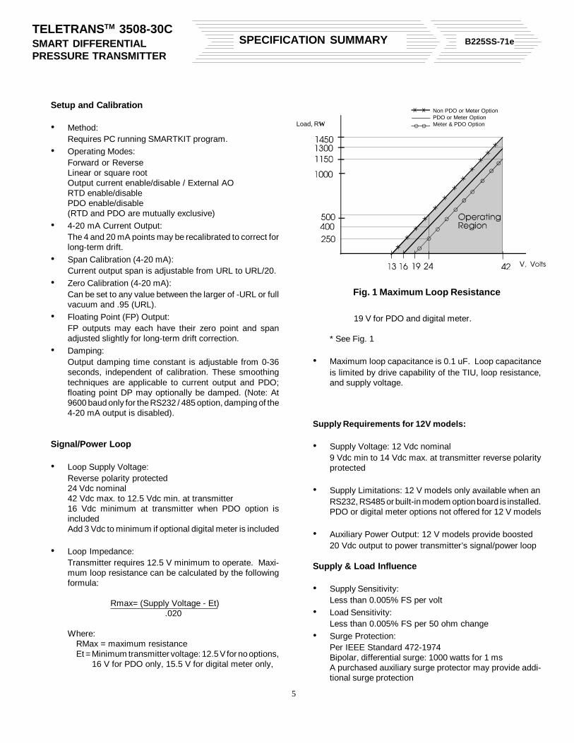
• Loop Supply Voltage:Reverse polarity protected24 Vdc nominal42 Vdc max. to 12.5 Vdc min. at transmitter16 Vdc minimum at transmitter when PDO option isincludedAdd 3 Vdc to minimum if optional digital meter is included
• Loop Impedance:Transmitter requires 12.5 V minimum to operate. Maxi-mum loop resistance can be calculated by the followingformula:
Rmax= (Supply Voltage - Et).020
Where:RMax = maximum resistanceEt = Minimum transmitter voltage: 12.5 V for no options,
16 V for PDO only, 15.5 V for digital meter only,
19 V for PDO and digital meter.
* See Fig. 1
• Maximum loop capacitance is 0.1 uF. Loop capacitanceis limited by drive capability of the TIU, loop resistance,and supply voltage.
Supply Requirements for 12V models:
• Supply Voltage: 12 Vdc nominal9 Vdc min to 14 Vdc max. at transmitter reverse polarityprotected
• Supply Limitations: 12 V models only available when anRS232, RS485 or built-in modem option board is installed.PDO or digital meter options not offered for 12 V models
• Auxiliary Power Output: 12 V models provide boosted20 Vdc output to power transmitter’s signal/power loop
Supply & Load Influence
• Supply Sensitivity:Less than 0.005% FS per volt
• Load Sensitivity:Less than 0.005% FS per 50 ohm change
• Surge Protection:Per IEEE Standard 472-1974Bipolar, differential surge: 1000 watts for 1 msA purchased auxiliary surge protector may provide addi-tional surge protection
Load, RΩ
Non PDO or Meter OptionPDO or Meter OptionMeter & PDO Option
• Differential and Static Pressure Temperature Effect:+0.25% of URL for any temperature between -40 C to+85° C(Note: This value represents maximum deviation thatoccurs from Temp changes. The T change will depend onthe T @ calibration. The T effect will gradually occur withreference from the T @ calibration)
• RTD Temperature Effect: + [.01 (22° C-Ambient)] °C• Estimated Sensor Temperature: Not applicable• Mounting Position Effect: +2 in H2O maximum which can
be calibrated out• Power Supply Effect: +0.005% of URL for all variables• Ripple and Noise: Per ISA 50.1, Section 4.6• Reproducibility: +0.1% in 1-hour period (Including hyster-
esis and repeatability)• Thermal Hysteresis (0 - 100" and 0 - 150" H2O ranges
only): thermal hysteresis will be. 1% or less in temperaturerange of -24 to 50° C for any temperature excusion in a 24hour time period
ENVIRONMENTAL SPECIFICATIONS
Temperature Limits
• Wet end (w/DC 200 fill):-40 to 185° F (-40 to 85° C)*
• Electronics:Operating: -40 to 185° F (-40 to 85° C)
• With Digital Display:-22 to 176° F (-30 to 80° C)
• Storage:-40 to 212° F (-40 to 100° C)*
*Low end limited to .5° F (-17.5° C) with Fluorolube fill(Special order only)
Humidity Limits
• 15-95% RH (non condensing) over electronics operatingtemperature range with cover in place
• Local indicator (digital):15% to 95% RH at 60° C max.15% to 50% RH at 80° C max.
• Conditions:Current output (only) twisted-pair wires; RTD or PDOcovers installed and wiring run in grounded conduit (doesnot include units with local indicators)
• DP and SP:+0.25% of URL @ 10 V/M, 20-500 MHz (SAMAPMC-33-1C)
• Less than +0.1% of URL for 10 to 500 Hz at 1 G on anyaxis per SAMA PMC-31-1
SPECIFICATIONS FOR OPTIONS
RS232/485
• Specific to RS232: Consists of four signals which aregalvanically isolated from the chassis, power and the 4-20mA loop via the internal type DC/DC power supply andopto-isolation.1) RXD - Receive data, into the 35082) TXD - Transmit data, from the 35083) RTS - Request to send, from the 35084) CTS - Clear to send, to the 35085) XCOM - Communications commonThe 3508 provides a minimum delay of 10 ms betweenassertion of RTS and beginning of data transmissionwhen CTS is tied to RTS. An external device (e.g. radio)may extend this time by delaying assertion of CTS afterRTS assertion if needed, to a maximum of three seconds.
• Specific to RS485: Utilizes 4-wires, and consists of twosignals, which are galvanically isolated from the chassis,power and the 4-20 mA loop via the internal type DC/DCpower supply and opto-isolation.1) RXD - Receive data, into the 3508 (2 lines)2) TXD - Transmit data, from the 3508 (2 lines)3) XCOM - Communications commonRS485 is a balanced system with two connections foreach signal. RTS and CTS are internally connected,providing a 10 ms delay between activation of the RS485transmitter and beginning of transmission. There is a
delay of approximately 50 microseconds following trans-mission before the RS485 transmitter disconnects fromthe line.Line termination: Line termination and voltage bias levelis handled externally by either the master or with add onexternal devices.Line fault: RS485 sets limits for line contention and lineshort at a maximum of 250 mA. The DC/DC supply willrestrict this to an even lower value.
• Supply Voltage: Two Options -9 to 14 volts: Nominal 24 volt requirement to power thebasic transmitter will be met by the DC/DC converterwhich will boost the supply to 18 to 28 volts. The converterwill also produce the additional floating supplies neces-sary for isolation.22 to 28 volts: The on board DC/DC converter will developthe additional floating supplies necessary for isolation.
Note: The transmitter must be externally powered for theRS232 / 485 options
• Transient Protection: Nominal protection against tran-sients on digital I/O via transorbs
Modem
• Operational Characteristics:- Modulation/Demodulation: Frequency Shift Keying (FSK)- Data Rate: 1200 baud- Frequencies: Per Bell 202 and 212 specifications- Output: Private Line: 0 dBm
Switched Network: -9 dBm- RTS/CTS Delays
Private Line -0 to 2.5 sec. in 10 ms increments leading0 to 250 ms in 1 ms increments trailingSwitched Network - 200 or 600 ms increments,leading and trailing
- Constant Carrier: Enable/Disable constant carrier whenin Private line mode
- RTS Antistreaming: Programmable true for 30 secondsor no time limit (Private line only). This limits themaximum amount of time a modem may put carrieron the line, and is intended as a fail-safe check.
- Send Long Space (PSTN): Send 4 second space whenRTS goes false or not
- Receiver Operating Range:0 to -43 dBm for carrier detect ONCarrier Detect OFF guaranteed at -48 dBmReceive data clamped to MARK when CD is OFFCarrier Detect Hysteresis 2 dBm
• Environmental Specifications:- Temperature: -20 to +70° C (-4 to 158° F) 212 operating
-40 to +70° C (-40 to 158° F) 202 operating-40 to +100° C (-40 to 212° F) storage
- Humidity: 15 to 95% Relative Humidity (non condensing) over the operating temperature range- Vibration: 1G for 15 - 150 HZ, 0.5 G for 150 - 2000 Hz- RFI Susceptibility: 10 V/m from 20 - 500 MHz
• Hazardous Locations:UL/CUL ApprovalExplosion-Proof for Class I, Division 1and 2, Groups C andD
PHYSICAL SPECIFICATIONS
• Diaphragm Material316 Stainless SteelHastelloy C
• Housing Material and ratingLow Copper Aluminum with Epoxy PaintNEMA 4X
• Local Indication3 1/2 Digit LCD Meter: Linear (0 to 100%), or inengineering unitsSize of digits = 0.3"Size of window = 1.13" (L) x 0.39" (W)Green backlightZero: can be adjusted approximately 20% of spanPolarity: Automatic (-) displayed
• RTD Sensor (Optional)2/3 wire, 100 ohm PT DIN 43760Lead length is 100 feet maximum (recommended)
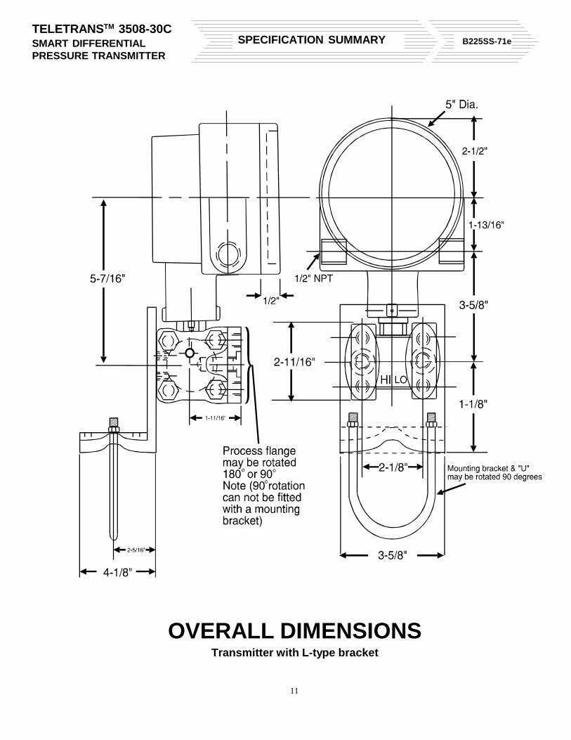
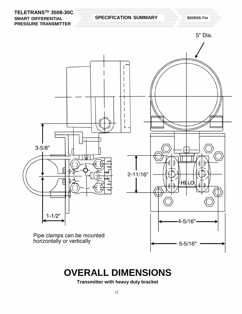
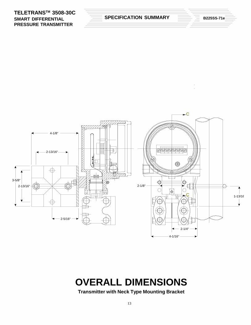
• Dimensions: Please refer to diagrams• Weight
Standard: 8 lbs.With Meter: 8 1/2 lbs.
• Interface Unit9 pin D female connection (PC compatible) at one endPair of wires with clip leads at other endwhich connects on to 4-20 mA loop4.5" x 2.4" x 1.3" Cast Aluminum case coated withepoxy paint