+ All Categories
Home > Documents > FITTING INSTRUCTIONS FOR R1 2000 - R&G RacingFITTING INSTRUCTIONS FOR LP0157BK LICENCE PLATE BRACKET...

FITTING INSTRUCTIONS FOR R1 2000 - R&G RacingFITTING INSTRUCTIONS FOR LP0157BK LICENCE PLATE BRACKET...

Date post: 01-Jun-2020
Category:
Upload: others
View: 2 times
Download: 0 times
Share this document with a friend
30
R&G Racing Unit 1, Shelley’s Lane, East Worldham, Alton, Hampshire, GU34 3AQ Tel: +44 (0)1420 89007 Fax: +44 (0)1420 87301 www.rg-racing.com Email: [email protected] FITTING INSTRUCTIONS FOR LP0157BK LICENCE PLATE BRACKET MV AGUSTA RIVALE 800 ’14- THIS KIT CONTAINS THE ITEMS PICTURED AND LABELLED BELOW. DO NOT PROCEED UNTIL YOU ARE SURE ALL PARTS ARE PRESENT. Please note that the way the kit is packed does not necessarily represent the way of mounting to the bike. THE PARTS SHOWN MAY BE REPRESENTATIVE ONLY (FOR CLARITY OF INSTRUCTIONS ONLY) 8 1 5 9 3 4 11 10 2 12 6 7 1 3 2 13 14 15 16 17 18
Transcript

R&G Racing

Unit 1, Shelley’s Lane, East Worldham, Alton, Hampshire, GU34 3AQ

Tel: +44 (0)1420 89007 Fax: +44 (0)1420 87301 www.rg-racing.com Email: [email protected]

FITTING INSTRUCTIONS FOR LP0157BK LICENCE PLATE BRACKET

MV AGUSTA RIVALE 800 ’14-

THIS KIT CONTAINS THE ITEMS PICTURED AND LABELLED BELOW.

DO NOT PROCEED UNTIL YOU ARE SURE ALL PARTS ARE PRESENT.

Please note that the way the kit is packed does not necessarily represent the way of mounting to the bike.

THE PARTS SHOWN MAY BE REPRESENTATIVE ONLY (FOR CLARITY OF INSTRUCTIONS ONLY)

1 12

8

13

3 16 1

5

9

3 4

11

10

2

12

6

7

1

3

2

13 14

15

16

17

18

R&G Racing

Unit 1, Shelley’s Lane, East Worldham, Alton, Hampshire, GU34 3AQ

Tel: +44 (0)1420 89007 Fax: +44 (0)1420 87301 www.rg-racing.com Email: [email protected]

LEGEND ITEM 1 = M5 x 20mm LONG BUTTON HEAD BOLTS (x6).

ITEM 2 = M5 WASHERS (x6).

ITEM 3 = M5 NYLOC NUTS (x6).

ITEM 4 = OEM INDICATOR COVER (TB0157 Part 4) (x1).

ITEM 5 = OEM INDICATOR MOUNTING BRACKET (TB0157 Part 3) (x1).

ITEM 6 = 2.5mm CABLE TIES (x3).

ITEM 7 = MINI INDICATOR MOUNTING BRACKET (TB0157 Part 2) (x1).

ITEM 8 = M6 x 35mm LONG COUNTERSUNK BOLTS (x2).

ITEM 9 = S0741 SPACERS (20mm long) (x2).

ITEM 10 = WIRING CONNECTORS (CON0014) (x3).

ITEM 11 = LICENCE PLATE BRACKET (TB0157 Part 1) (x1).

ITEM 12 = M6 x 12mm LONG BUTTON HEAD BOLTS (x2).

ITEM 13 = M5 x 20mm LONG COUNTERSUNK BOLTS (x2).

ITEM 14 = S0742 SPACERS (5.5mm long) (x2).

ITEM 15 = SELF ADHESIVE CABLE CLIPS (x2).

ITEM 16 = 150mm LENGTH OF HEATSHRINK (x3).

ITEM 17 = REFLECTOR (x1).

ITEM 18 = LA0002 No. PLATE LIGHT ASSEMBLY (x1).

Please note that in cases where kits are packed with rubber washers holding the components onto

the bolt – the rubber washers should be thrown away!

TOOLS REQUIRED Set of metric Allen keys to include 2.5, 3 & 4mm A/F sizes.

Socket set to include 6 & 8mm sockets and wrench.

Phillips screwdriver.

Small amount of superglue.

Cable cutters.

Picture 1 Picture 2

R&G Racing

Unit 1, Shelley’s Lane, East Worldham, Alton, Hampshire, GU34 3AQ

Tel: +44 (0)1420 89007 Fax: +44 (0)1420 87301 www.rg-racing.com Email: [email protected]

Picture 3

Picture 4

Picture 5

Picture 6

Picture 7

Picture 8

R&G Racing

Unit 1, Shelley’s Lane, East Worldham, Alton, Hampshire, GU34 3AQ

Tel: +44 (0)1420 89007 Fax: +44 (0)1420 87301 www.rg-racing.com Email: [email protected]

Picture 9

Picture 10

Picture 11

Picture 12

Picture 13 Picture 14

R&G Racing

Unit 1, Shelley’s Lane, East Worldham, Alton, Hampshire, GU34 3AQ

Tel: +44 (0)1420 89007 Fax: +44 (0)1420 87301 www.rg-racing.com Email: [email protected]

Picture 15 Picture 16

Picture 17 Picture 18

Picture 19 Picture 20

R&G Racing

Unit 1, Shelley’s Lane, East Worldham, Alton, Hampshire, GU34 3AQ

Tel: +44 (0)1420 89007 Fax: +44 (0)1420 87301 www.rg-racing.com Email: [email protected]

Picture 21

Picture 22

Picture 23 Picture 24

Picture 25 Picture 26

R&G Racing

Unit 1, Shelley’s Lane, East Worldham, Alton, Hampshire, GU34 3AQ

Tel: +44 (0)1420 89007 Fax: +44 (0)1420 87301 www.rg-racing.com Email: [email protected]

Picture 27 Picture 28

Picture 29 Picture 30

Picture 31 Picture 32

R&G Racing

Unit 1, Shelley’s Lane, East Worldham, Alton, Hampshire, GU34 3AQ

Tel: +44 (0)1420 89007 Fax: +44 (0)1420 87301 www.rg-racing.com Email: [email protected]

FITTING INSTRUCTIONS

The fitting instructions show how to fit the R&G Tail Tidy with the rear wheel and licence plate

mounting arm in place. To make fitting easier, either one of these can be removed to improve

accessibility.

To fit the R&G tail tidy, start off by removing the two bolts that secure the wiring cover in place

on the swingarm, located on the back side of the rear wheel axle housing, as shown in picture 1.

Undo the three wiring connectors for the indicators and licence plate illuminator, as shown in

picture 2. It is a good idea to note which connectors match, to make re-fitting easier.

On the back side of the licence plate mounting arm, there are three 2.5mm button head bolts.

Remove these three bolts and the plastic wiring cover to gain access to the wiring. Two are shown

in pictures 3 & 4 through the rear wheel, the third is higher up to the side of the tyre.

On the licence plate bracket, remove the two button head bolts, as arrowed in picture 5.

Gently place this bracket to one side, before removing the four button head bolts and two hex

headed bolts now uncovered, as shown in picture 6.

There is an additional button head bolt on the underside of the right side of the rear hugger.

Remove this also, before gently pulling the rear hugger/licence plate assembly away and resting on

the back wheel, as shown in picture 7.

Loosen the two lower bolts and remove the two upper bolts on the back side of the mounting arm

as shown in picture 8.

With these two bolts removed, the wiring can be removed through the side, as shown in picture 9.

With the wiring removed, the entire hugger/licence plate bracket can be removed from the bike, as

shown in picture 10.

If you intend to fit the R&G mini indicators, skip the following five stages.

If you intend to re-use the OEM indicators, remove them from the hugger by removing the six

button head bolts and loosen the two Phillips screws which secure the cable guides in place,

allowing the indicators and wiring to come away from the hugger assembly, as shown in picture

11.

Take the R&G OEM Indicator Mounting Bracket (item 5 – TB0157 Part 3) and place on a

workbench along with both OEM indicators, as shown in picture 12. Please note that when re-

using the OEM indicators on the R&G Tail Tidy, the indicators are on the opposite sides to

standard. Please ensure when re-connecting the wiring that it is reversed from the standard setup.

Take three of the M5 x 20mm long button head bolts (item 1) and offer them through the holes in

the mounting bracket and then through the rubber mounted bushes in the indicator housing, as

shown in picture 13.

On the back, locate the OEM Indicator Cover (item 4 – TB0157 Part 4) over the three holes to

align with the mounting bracket, before loosely fitting three M5 washers (item 2) and M5 nyloc

nuts (item 3) over the exposed ends of the thread, as shown in picture 14. Take care to ensure the

wiring sits in the small void at the top of the cover and locates around the clip on the indicator

housing.

Fit the remaining indicator using the same process. Once fitted, tighten all bolts evenly (do not

overtighten - the nyloc nuts will remain secure), as shown in picture 15. The mounting bracket to

re-use the OEM indicators is now prepared.

To fit the R&G Mini Indicators, take TB0157 Part 2 (item 7) and fit the mini indicators through the

holes on either side before fitting the nut on the reverse. (Please use the heatshrink (item 16) to

protect the indicator wires), as shown in picture 16. (If using the R&G Bulb Mini Indicators, simply

connect the two bullet connectors to those on one of the wiring connectors (item 10 – CON0014)

(black to black and black/white to black/white). If using the R&G LED Mini Indicators or Aero

R&G Racing

Unit 1, Shelley’s Lane, East Worldham, Alton, Hampshire, GU34 3AQ

Tel: +44 (0)1420 89007 Fax: +44 (0)1420 87301 www.rg-racing.com Email: [email protected]

Indicators, a small 5w resistor will be required on each indicator to achieve the correct flash rate

(available separately). To fit, simply connect in line on each indicator, between the indicator

wiring and the wiring on the connector (item 10 – CON0014) (black to black and black/white to

yellow for the Aero Indicators), as shown in picture 17.

Take the indicator mounting bracket and rest it on the rear wheel whilst feeding the wiring down

the inside of the mounting arm in the same way the original wiring was removed, as shown in

picture18. Cable ties are provided in the kit to clip the wires together to keep them neatly together.

Take the R&G Licence Plate Bracket (item 11 – TB0157 Part 1) and fit the R&G license plate

illuminator (item 18), as shown in picture 19. Use a small amount of superglue to stick the light

shroud in position. Fit one length of heatshrink to the wires and tighten the nuts on the rear along

with fitting a wiring connector (item 10 – CON0014) (black to black and red to yellow), as shown

in picture 20.

The R&G licence plate bracket can now be offered up to the rear of the bike. Take the two M6 x

12mm long button head bolts (item 12) and locate through the two lower mounting holes into the

threaded bosses on the metal arm underneath, as shown in picture 21.

Locate the illuminator wiring neatly down inside the mounting arm along with the indicator wiring,

as shown in picture 22.

With the wiring in place and tucked inside the mounting arm, tighten the bolt that secures the cable

clip along with the two bolts that secure the plastic cover in place and re-fit the protective cable

sleeve, as shown in pictures 23, 24 and 25.

At this stage it is advisable to connect the wiring connectors and ensure the correct operation and

flash rates of the lights. If re-fitting the OEM indicators, the red wire should connect to the

connector marked “L” and the white wire should connect to the connector marked “R” (the

opposite to standard).

Re-fit the two mounting arm bracket bolts and then tighten all four bolts, taking care to ensure no

wiring is trapped, as shown in picture 26.

Re-fit the plastic cover using the two bolts from the underside of the swingarm/rear axle, ensuring

all the connectors are protected, as shown in picture 27.

Take the two M5 x 20mm long countersunk bolts (item 13) and locate through the two lower

countersunk holes on the licence plate bracket, ensuring that the shorter spacers (item 14 – S0472 –

5.5mm long) sit between the licence plate bracket and threaded boss on the mounting bracket

before loosely tightening, as shown in picture 28.

If using the OEM indicators, take the assembly and offer it up to the top two mounting holes, as

shown in picture 29. Take the two M6 x 35mm long countersunk bolts (item 8) and locate through

the remaining countersunk holes on the licence plate bracket, then through one of the remaining

longer spacers (item 9 – S0741 – 20mm long), then the mounting holes on the indicator bracket

before loosely tightening into the threaded boss on the mounting bracket, as shown in picture 30.

If using the bracket with the mini indicators, position the indicator bracket above the spacer,

opposed to below it, as shown in picture 31. There are also two slots in the middle of the bracket to

cable tie any loose wiring to.

Tighten the six bolts that secure the licence plate bracket in place, ensuring no wiring is trapped on

the reverse.

The OEM indicators can be set in a narrow position as well as a wider position to suit wider

licence plates. This can be adjusted by using the different mounting holes in the OEM Indicator

Mounting Bracket (TB0157 Part 3) to space the indicators wider apart, as shown in picture 32.

Re-fit the licence plate (it may require drilling).

Depending on local laws, attach enclosed reflector in an appropriate location.

Test the license plate illuminator and all lights before riding.

R&G Racing

Unit 1, Shelley’s Lane, East Worldham, Alton, Hampshire, GU34 3AQ

Tel: +44 (0)1420 89007 Fax: +44 (0)1420 87301 www.rg-racing.com Email: [email protected]

ISSUE 1 20/12/13 (AR)

Digital copies of these instructions are available to download from www.rg-racing.com

CONSUMER NOTICE

The catalogue description and any exhibition of samples are only broad indications of the Products and R&G may make design

changes which do not diminish their performance or visual appeal and supplying them in such state shall conform to the order. The

Buyer acknowledges no representation or warranty (other than as to title) has been given or will apply to the Products other than those

in R&G’s order or confirmation and the Buyer confirms it has chosen the Products as being of merchantable quality and suitable for its particular purposes. Where R&G fits the Products or undertakes other services it shall exercise reasonable skill and care and rectify any

fault free of charge unless the workmanship has been disturbed. The Buyer is responsible for ensuring that the warranty on the

motorcycle is not affected by the fitting of the Products. On return of any defective Products R&G shall at its option either supply a replacement or refund the purchase money but shall not be liable if the Products have been modified or used or maintained otherwise

than in accordance with R&G’s or manufacturer’s instructions and good engineering practice or if the defect arises from accident or

neglect. Other than identified above and subject to R&G not limiting its liability for causing death and personal injury, it shall not be liable for indirect or consequential loss and otherwise its liability shall be limited to the amounts paid by the Buyer for the Products or

the fitting or service concerned. These terms do not affect the Buyer’s statutory rights.

R&G RACING RETURNS POLICY (NON-FAULTY GOODS)

Returns must be pre-authorised (if not pre-authorised the return will be rejected). Goods may only be returned direct to us if they were

purchased direct from us (customer must prove if necessary). Otherwise to be returned to original vendor. Goods must be in re-sellable

condition, in the opinion of R&G Racing. All returns are subject to a 25% restocking and handling fee (25% of the gross value exc. P&P – at the prevailing price at time of purchase). The customer must pay any and all carriage charges. No returns of discontinued

products, unless within 14 days of purchase. This policy does not affect your statutory rights and does not refer to faulty goods.

R&G Racing

Unit 1, Shelley’s Lane, East Worldham, Alton, Hampshire, GU34 3AQ

Tel: +44 (0)1420 89007 Fax: +44 (0)1420 87301 www.rg-racing.com Email: [email protected]

INSTRUCTIONS DE MONTAGE POUR LP0157BK SUPPORT DE PLAQUE

MV AGUSTA RIVALE 800 ’14-

Assurez vous que toutes les pièces soient présentes avant de procéder au montage.

La façon dont le kit est emballé ne correspond pas forcément à la façon de monter les pieces sur la moto.

LES PIECES PRESENTEES PEUVENT N’ETRE QUE REPRESENTATIVES, AFIN DE FACILITER ET CLARIFIER LES INSTRUCTIONS

DE MONTAGE.

1 12

8

13

3 16 1

9

11

10

2

12

6

7

1

2

13 14

15

16

17

18

5 3 4

R&G Racing

Unit 1, Shelley’s Lane, East Worldham, Alton, Hampshire, GU34 3AQ

Tel: +44 (0)1420 89007 Fax: +44 (0)1420 87301 www.rg-racing.com Email: [email protected]

LEGENDE ARTICLE 1 = M5 x 20mm Boulons (x6). ARTICLE 2 = M5 Rondelles (x6). ARTICLE 3 = M5 Ecrous (x6). ARTICLE 4 = Cache clignotant d’origine (TB0157 Partie 4) (x1). ARTICLE 5 = Support de fixation clignotant d’origine (TB0157 Partie 3) (x1). ARTICLE 6 = 2.5mm Colliers de serrage (x3). ARTICLE 7 = Support de fixation mini clignotant (TB0157 Part 2) (x1). ARTICLE 8 = M6 x 35mm Boulons (x2). ARTICLE 9 = S0741 Entretoises (20mm de long) (x2). ARTICLE 10 = Connecteurs de fils (CON0014) (x3). ARTICLE 11 = Support de plaque (TB0157 Partie 1) (x1). ARTICLE 12 = M6 x 12mm Boulons (x2). ARTICLE 13 = M5 x 20mm Boulons (x2). ARTICLE 14 = S0742 Entretoises (5.5mm de long) (x2). ARTICLE 15 = Clips câbles autocollants (x2). ARTICLE 16 = 150mm Longueur thermo rétractable (x3). ARTICLE 17 = Réfléchissant (x1). ARTICLE 18 = LA0002 No. Assemblage feu de plaque (x1).

NOTEZ QUE SI LES KITS SONT EMBALLES AVEC DES RONDELLES EN CAOUTCHOUC SERVANT A TENIR LES COMPOSANTS, CES

RONDELLES DOIVENT ETRE JETEES!

OUTILS REQUIS

Jeu de clés Allen 2.5, 3 & 4mm A/F cotés

Jeu de clés 6 & 8mm.

Tournevis cruciforme.

Une peu de superglue.

Pince coupante.

Photo 1 Photo 2

R&G Racing

Unit 1, Shelley’s Lane, East Worldham, Alton, Hampshire, GU34 3AQ

Tel: +44 (0)1420 89007 Fax: +44 (0)1420 87301 www.rg-racing.com Email: [email protected]

Photo 3

Photo 4

Photo 5

Photo 6

Photo 7

Photo 8

R&G Racing

Unit 1, Shelley’s Lane, East Worldham, Alton, Hampshire, GU34 3AQ

Tel: +44 (0)1420 89007 Fax: +44 (0)1420 87301 www.rg-racing.com Email: [email protected]

Photo 9

Photo 10

Photo 11

Photo 12

Photo 13 Photo 14

R&G Racing

Unit 1, Shelley’s Lane, East Worldham, Alton, Hampshire, GU34 3AQ

Tel: +44 (0)1420 89007 Fax: +44 (0)1420 87301 www.rg-racing.com Email: [email protected]

Photo 15 Photo 16

Photo 17 Photo 18

Photo 19 Photo 20

R&G Racing

Unit 1, Shelley’s Lane, East Worldham, Alton, Hampshire, GU34 3AQ

Tel: +44 (0)1420 89007 Fax: +44 (0)1420 87301 www.rg-racing.com Email: [email protected]

Photo 21

Photo 22

Photo 23 Photo 24

Photo 25 Photo 26

R&G Racing

Unit 1, Shelley’s Lane, East Worldham, Alton, Hampshire, GU34 3AQ

Tel: +44 (0)1420 89007 Fax: +44 (0)1420 87301 www.rg-racing.com Email: [email protected]

Photo 27 Photo 28

Photo 29 Photo 30

Photo 31 Photo 32

R&G Racing

Unit 1, Shelley’s Lane, East Worldham, Alton, Hampshire, GU34 3AQ

Tel: +44 (0)1420 89007 Fax: +44 (0)1420 87301 www.rg-racing.com Email: [email protected]

Instructions de montage:

Les instructions de montage indiquent comment monter le support de plaque R&G avec la roue arrière et l’arbre support de plaque en place. Pour faciliter l’installation, ces 2 parties peuvent être enlevées pour améliorer l’accessibilité.

Pour monter le support de plaque, commencez par enlever les 2 boulons qui fixent le cache en place sur le bras oscillant, placé à l’arrière du carter d’essieu de la roue arrière (Photo 1).

Défaire les 3 connecteurs de fils pour les clignotants et le feu de plaque (Photo 2). C’est une bonne idée de noter les correspondances entre connecteurs pour faciliter le remontage.

Sur la face arrière de l’arbre de fixation de plaque, il y a 3 boulons 2,5mm. Enlever ces 3 boulons et le cache fils en plastic pour faciliter l’accès aux fils. 2 des 3 sont visibles sur les photos 3 & 4 à travers la roue arrière, le 3e est un peu plus haut sur le coté du pneu.

Sur le support de plaque, enlever les 2 boulons (Photo 5).

Placer ce support d’un coté, avant d’enlever les 4 boulons et 2 boulons hexagonales découverts (Photo 6).

Il y a une boulon supplémentaire sur le partie inférieure du coté droit du garde boue arrière. Enlever le aussi, avant de tirer l’assemblage feu de plaque/garde boue arrière vers l’extérieur et en restant sur la roue arrière (Photo 7).

Desserrer les 2 boulons inférieurs et enlever les 2 boulons supérieurs sur la face arrière de l’arbre de fixation (Photo8).

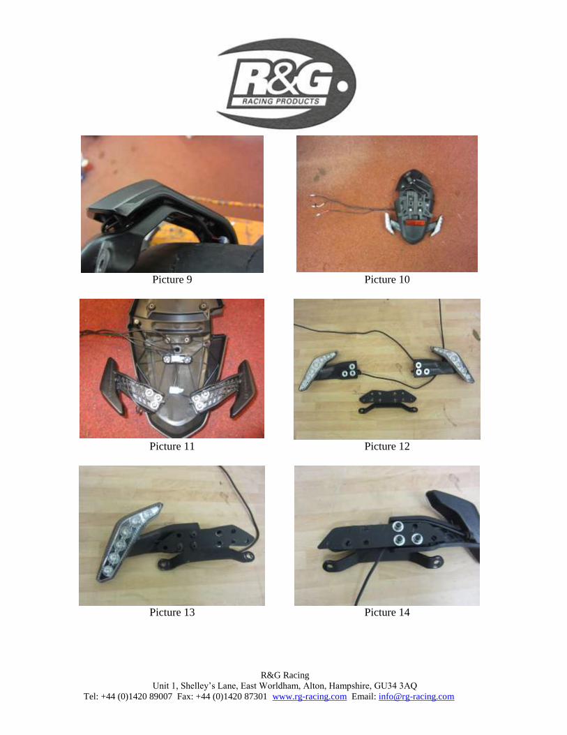
Une fois ces 2 boulons enlevés, le fil peut être enlevé à travers le coté (Photo 9).

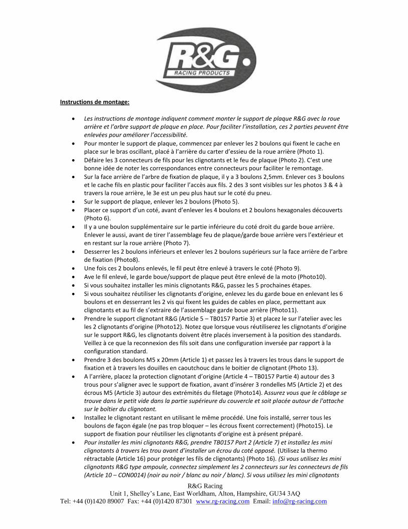
Ave le fil enlevé, le garde boue/support de plaque peut être enlevé de la moto (Photo10).

Si vous souhaitez installer les minis clignotants R&G, passez les 5 prochaines étapes.

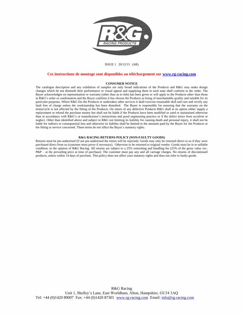
Si vous souhaitez réutiliser les clignotants d’origine, enlevez les du garde boue en enlevant les 6 boulons et en desserrant les 2 vis qui fixent les guides de cables en place, permettant aux clignotants et au fil de s’extraire de l’assemblage garde boue arrière (Photo11).

Prendre le support clignotant R&G (Article 5 – TB0157 Partie 3) et placez le sur l’atelier avec les les 2 clignotants d’origine (Photo12). Notez que lorsque vous réutiliserez les clignotants d’origine sur le support R&G, les clignotants doivent être placés inversement à la position des standards. Veillez à ce que la reconnexion des fils soit dans une configuration inversée par rapport à la configuration standard.

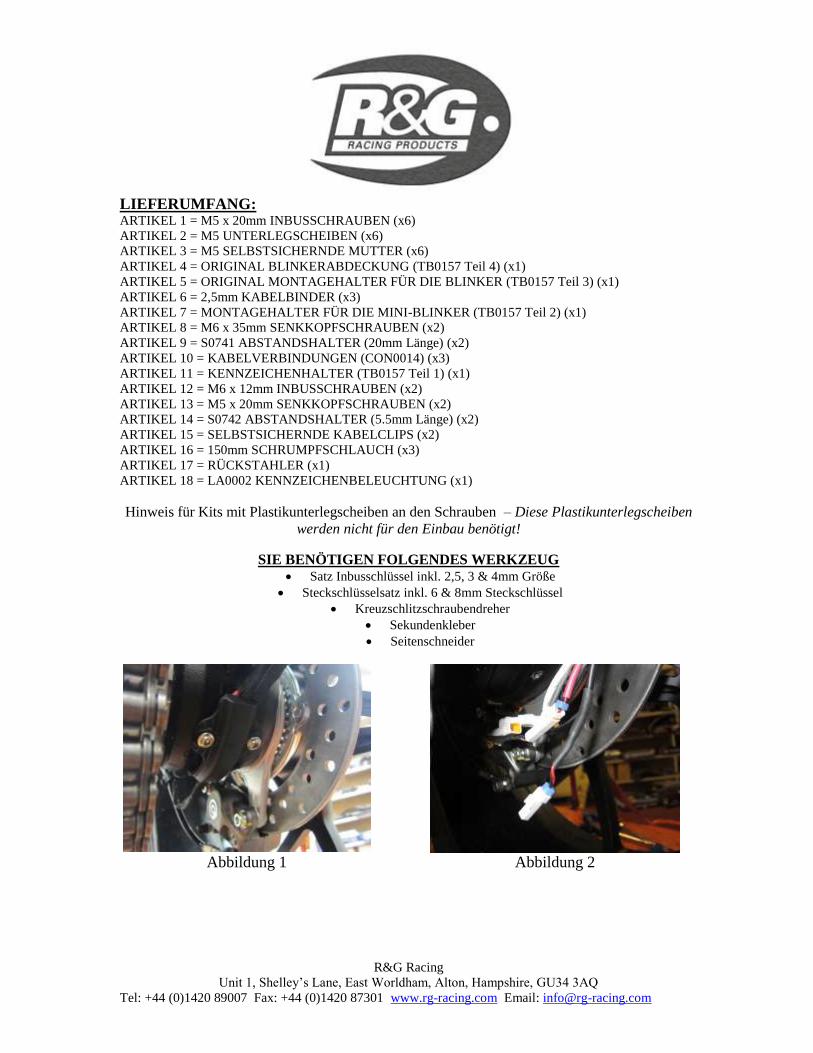
Prendre 3 des boulons M5 x 20mm (Article 1) et passez les à travers les trous dans le support de fixation et à travers les douilles en caoutchouc dans le boitier de clignotant (Photo 13).

A l’arrière, placez la protection clignotant d’origine (Article 4 – TB0157 Partie 4) autour des 3 trous pour s’aligner avec le support de fixation, avant d’insérer 3 rondelles M5 (Article 2) et des écrous M5 (Article 3) autour des extrémités du filetage (Photo14). Assurez vous que le câblage se trouve dans le petit vide dans la partie supérieure du couvercle et soit placée autour de l'attache sur le boîtier du clignotant.

Installez le clignotant restant en utilisant le même procédé. Une fois installé, serrer tous les boulons de façon égale (ne pas trop bloquer – les écrous fixent correctement) (Photo15). Le support de fixation pour réutiliser les clignotants d’origine est à présent préparé.

Pour installer les mini clignotants R&G, prendre TB0157 Part 2 (Article 7) et installez les mini clignotants à travers les trou avant d’installer un écrou du coté opposé. (Utilisez la thermo rétractable (Article 16) pour protéger les fils de clignotants) (Photo 16). (Si vous utilisez les mini clignotants R&G type ampoule, connectez simplement les 2 connecteurs sur les connecteurs de fils (Article 10 – CON0014) (noir au noir / blanc au noir / blanc). Si vous utilisez les mini clignotants

R&G Racing

Unit 1, Shelley’s Lane, East Worldham, Alton, Hampshire, GU34 3AQ

Tel: +44 (0)1420 89007 Fax: +44 (0)1420 87301 www.rg-racing.com Email: [email protected]

R&G type LED ou Aero, une résistance 5w sera nécessaire sur chaque clignotant pour avoir le bon niveau de luminosité (disponible séparément). Pour installer, connectez simplement en ligne sur chaque clignotant, entre le fil de clignotant et le fil sur le connecteur (Article 10 – CON0014) ((noir au noir / blanc au jaune pour les clignotants Aero), Photo17.

Prendre le support clignotant et laissez-le sur la roue arrière tout en passant les fils à l’intérieur du bras de fixation de la même façon qu’il a été enlevé (Photo18). Des colliers de serrage sont fournis dans le kit pour serrer les fils ensemble proprement.

Prendre le support de plaque R&G (Article 11 – TB0157 Partie 1) et installez le feu de plaque R&G (Article 18) (Photo19). Utiliser un peu de superglue pour coller le linceul de lumière en position. Installer une longueur de thermo rétractable sur les fils et serrer les écrous à l’arrière en montant le connecteur de fils (Article 10 – CON0014) (noir au noir et rouge à jaune) (Photo 20).

Le support de plaque R&G peut à présent être monté à l’arrière de la moto. Prendre les 2 boulons M6 x 12mm (Article 12) et placez les à travers les 2 trous de fixation inférieurs dans les patrons filetés sur le bras de métal au dessous (Photo21).

Placer le fil de clignotant bien à l’intérieur du bras de fixation avec le fil (Photo 22).

Avec les fils en place cachés à l'intérieur du bras de montage, serrer le boulon qui fixe le clip de câble avec les 2 boulons qui fixent la protection plastic en placer et remettre la gaine de protection de câble (Photos 23, 24 et 25).

A ce stade, il est conseillé de connecter les connecteurs de fils et de vérifier que l’éclairage fonctionne avec le bon niveau de luminosité. Si vous réinstallez les clignotants d’origine, le fil rouge doit se connecter au connecteur marqué “L” et le fil blanc doit se connecter au connecteur marqué “R” (l’opposé au standard).

Remettre les 2 boulons de l’arbre support en métal puis serrer les 4 boulons, en faisant attention à ce qu’aucun fil ne soit pincé (Photo 26).

Remettre la protection plastic en utilisant les 2 boulons par le dessous du bras oscillant/ Axe arrière, en veillant à ce que tous les connecteurs soient protégés (Photo 27).

Prendre les 2 boulons M5 x 20mm (Article 13) et placez les à travers les 2 trous inférieurs sur le support de plaque, en veillant à ce que les entretoises les plus courtes (Article 14 – S0472 – 5.5mm de long) se placent entre le support de plaque et le patron fileté sur le support de fixation avant de serrer légèrement (Photo28).

Si vous utilisez les clignotants d’origine, prendre l’ensemble et montez le sur les 2 trous supérieurs (Photo 29). Prendre les 2 boulons M6 x 35mm (Article 8) et passez les à travers les trous restants sur le support de plaque, puis à travers une des entretoises restantes (Article 9 – S0741 – 20mm de long), puis les trous de fixation sur le support de clignotant avant de serrer légèrement dans le patron fileté sur le support de fixation (Photo 30).

Si vous utilisez les support avec les minis clignotants, positionnez le support de clignotant au dessus de l’entretoise (Photo 31). Il y a aussi 2 fentes dans le milieu du support pour serrer les fils avec des colliers de serrage.

Serrer les 6 boulons qui fixent le support de plaque en place, en veillant à ce qu’aucun fil ne soit pincé.

Les clignotants d’origine peuvent être mis dans une position aussi bien étroite que large selon la largeur de la plaque. Vous pouvez ajuster en utilisant les trous différents dans le support de fixation clignotant (TB0157 Partie 3) pour espacer les clignotants entre eux (Photo 32).

Remettre la plaque d’immatriculation (peut nécessiter un perçage).

Selon la loi locale, monter les réflecteurs (article 10) aux emplacements appropriés.

Revérifiez que les clignotants et les feux de plaque fonctionnent bien avant de prendre la route.

R&G Racing

Unit 1, Shelley’s Lane, East Worldham, Alton, Hampshire, GU34 3AQ

Tel: +44 (0)1420 89007 Fax: +44 (0)1420 87301 www.rg-racing.com Email: [email protected]

ISSUE 1 20/12/13 (AR)

Ces instructions de montage sont disponibles au téléchargement sur www.rg-racing.com

CONSUMER NOTICE

The catalogue description and any exhibition of samples are only broad indications of the Products and R&G may make design

changes which do not diminish their performance or visual appeal and supplying them in such state shall conform to the order. The

Buyer acknowledges no representation or warranty (other than as to title) has been given or will apply to the Products other than those

in R&G’s order or confirmation and the Buyer confirms it has chosen the Products as being of merchantable quality and suitable for its particular purposes. Where R&G fits the Products or undertakes other services it shall exercise reasonable skill and care and rectify any

fault free of charge unless the workmanship has been disturbed. The Buyer is responsible for ensuring that the warranty on the

motorcycle is not affected by the fitting of the Products. On return of any defective Products R&G shall at its option either supply a replacement or refund the purchase money but shall not be liable if the Products have been modified or used or maintained otherwise

than in accordance with R&G’s or manufacturer’s instructions and good engineering practice or if the defect arises from accident or

neglect. Other than identified above and subject to R&G not limiting its liability for causing death and personal injury, it shall not be liable for indirect or consequential loss and otherwise its liability shall be limited to the amounts paid by the Buyer for the Products or

the fitting or service concerned. These terms do not affect the Buyer’s statutory rights.

R&G RACING RETURNS POLICY (NON-FAULTY GOODS)

Returns must be pre-authorised (if not pre-authorised the return will be rejected). Goods may only be returned direct to us if they were

purchased direct from us (customer must prove if necessary). Otherwise to be returned to original vendor. Goods must be in re-sellable

condition, in the opinion of R&G Racing. All returns are subject to a 25% restocking and handling fee (25% of the gross value exc. P&P – at the prevailing price at time of purchase). The customer must pay any and all carriage charges. No returns of discontinued

products, unless within 14 days of purchase. This policy does not affect your statutory rights and does not refer to faulty goods.

R&G Racing

Unit 1, Shelley’s Lane, East Worldham, Alton, Hampshire, GU34 3AQ

Tel: +44 (0)1420 89007 Fax: +44 (0)1420 87301 www.rg-racing.com Email: [email protected]

MONTAGEANLEITUNG FÜR LP0157BK KENNZEICHENHALTER

MV AGUSTA RIVALE 800 ’AB MODELL 2014

ALLE TEILE SIND UNTEN ABGEBILDET UND GEKENNZEICHNET. BEVOR SIE MIT DER

MONTAGE BEGINNEN, ÜBERPRÜFEN SIE, DASS ALLE TEILE VORHANDEN SIND.

Hinweis: Die Verpackung der Teile stellt nicht die Reihenfolge der Montage dar.

DIE UNTEN ABGEBILDETEN TEILE DIENEN LEDIGLICH ZUR ERKLÄRUNG

1 12

8

13

3 16 1

9

11

10

2

12

6

7

1

2

13 14

15

16

17

18

R&G Racing

Unit 1, Shelley’s Lane, East Worldham, Alton, Hampshire, GU34 3AQ

Tel: +44 (0)1420 89007 Fax: +44 (0)1420 87301 www.rg-racing.com Email: [email protected]

LIEFERUMFANG: ARTIKEL 1 = M5 x 20mm INBUSSCHRAUBEN (x6)

ARTIKEL 2 = M5 UNTERLEGSCHEIBEN (x6)

ARTIKEL 3 = M5 SELBSTSICHERNDE MUTTER (x6)

ARTIKEL 4 = ORIGINAL BLINKERABDECKUNG (TB0157 Teil 4) (x1)

ARTIKEL 5 = ORIGINAL MONTAGEHALTER FÜR DIE BLINKER (TB0157 Teil 3) (x1)

ARTIKEL 6 = 2,5mm KABELBINDER (x3)

ARTIKEL 7 = MONTAGEHALTER FÜR DIE MINI-BLINKER (TB0157 Teil 2) (x1)

ARTIKEL 8 = M6 x 35mm SENKKOPFSCHRAUBEN (x2)

ARTIKEL 9 = S0741 ABSTANDSHALTER (20mm Länge) (x2)

ARTIKEL 10 = KABELVERBINDUNGEN (CON0014) (x3)

ARTIKEL 11 = KENNZEICHENHALTER (TB0157 Teil 1) (x1)

ARTIKEL 12 = M6 x 12mm INBUSSCHRAUBEN (x2)

ARTIKEL 13 = M5 x 20mm SENKKOPFSCHRAUBEN (x2)

ARTIKEL 14 = S0742 ABSTANDSHALTER (5.5mm Länge) (x2)

ARTIKEL 15 = SELBSTSICHERNDE KABELCLIPS (x2)

ARTIKEL 16 = 150mm SCHRUMPFSCHLAUCH (x3)

ARTIKEL 17 = RÜCKSTAHLER (x1)

ARTIKEL 18 = LA0002 KENNZEICHENBELEUCHTUNG (x1)

Hinweis für Kits mit Plastikunterlegscheiben an den Schrauben – Diese Plastikunterlegscheiben

werden nicht für den Einbau benötigt!

SIE BENÖTIGEN FOLGENDES WERKZEUG Satz Inbusschlüssel inkl. 2,5, 3 & 4mm Größe

Steckschlüsselsatz inkl. 6 & 8mm Steckschlüssel

Kreuzschlitzschraubendreher

Sekundenkleber

Seitenschneider

Abbildung 1 Abbildung 2

R&G Racing

Unit 1, Shelley’s Lane, East Worldham, Alton, Hampshire, GU34 3AQ

Tel: +44 (0)1420 89007 Fax: +44 (0)1420 87301 www.rg-racing.com Email: [email protected]

Abbildung 3

Abbildung 4

Abbildung 5

Abbildung 6

Abbildung 7

Abbildung 8

R&G Racing

Unit 1, Shelley’s Lane, East Worldham, Alton, Hampshire, GU34 3AQ

Tel: +44 (0)1420 89007 Fax: +44 (0)1420 87301 www.rg-racing.com Email: [email protected]

Abbildung 9

Abbildung 10

Abbildung 11

Abbildung 12

Abbildung 13 Abbildung 14

R&G Racing

Unit 1, Shelley’s Lane, East Worldham, Alton, Hampshire, GU34 3AQ

Tel: +44 (0)1420 89007 Fax: +44 (0)1420 87301 www.rg-racing.com Email: [email protected]

Abbildung 15 Abbildung 16

Abbildung 17 Abbildung 18

Abbildung 19 Abbildung 20

R&G Racing

Unit 1, Shelley’s Lane, East Worldham, Alton, Hampshire, GU34 3AQ

Tel: +44 (0)1420 89007 Fax: +44 (0)1420 87301 www.rg-racing.com Email: [email protected]

Abbildung 21

Abbildung 22

Abbildung 23 Abbildung 24

Abbildung 25 Abbildung 26

R&G Racing

Unit 1, Shelley’s Lane, East Worldham, Alton, Hampshire, GU34 3AQ

Tel: +44 (0)1420 89007 Fax: +44 (0)1420 87301 www.rg-racing.com Email: [email protected]

Abbildung 27 Abbildung 28

Abbildung 29 Abbildung 30

Abbildung 31 Abbildung 32

R&G Racing

Unit 1, Shelley’s Lane, East Worldham, Alton, Hampshire, GU34 3AQ

Tel: +44 (0)1420 89007 Fax: +44 (0)1420 87301 www.rg-racing.com Email: [email protected]

MONTAGEANLEITUNG

Diese Montageanleitung erklärt wie Sie den R&G Kennzeichenhalter montieren, ohne das

Hinterrad oder den Montagearm für das Kennzeichen abzubauen. Um die Montage jedoch zu

erleichtern und einen besseren Zugang zu ermöglichen, können Sie einen dieser Teile abmontieren.

Entfernen Sie die zwei Schrauben, die die Kabelabdeckung am Schwingarm befestigen – diese sind

auf der Rückseite des Gehäuses für die Hinterradachse – siehe Abbildung 1.

Lösen Sie die drei Kabel-Steckverbindungen für die Blinker und die Kennzeichenbeleuchtung –

siehe Abbildung 2. Notieren Sie nun die Kabelverbindungen, um den Zusammenbau später zu

erleichtern.

Auf der Rückseite des Montagearms für das Kennzeichen sind drei 2,5mm

Halbrundkopfschrauben. Entfernen Sie diese drei Schrauben und die Plastik-Kabelabdeckung, um

Zugang zu der Verkabelung zu ermöglichen. Zwei dieser Schrauben sind durch das Hinterrad in

Abbildungen 3 & 4 zu sehen, die dritte ist höher positioniert, seitlich vom Reifen.

Entfernen Sie die zwei Inbusschrauben, die in Abbildung 5 mit Pfeilen gekennzeichnet sind.

Den Halter vorsichtig zur Seite legen und danach die vier übrigen Inbusschrauben und die zwei

Sechskantschrauben, die jetzt nicht mehr abgedeckt sind, entfernen (wie in Abbildung 6

abgebildet).

Eine zusätzliche Halbrundkopfschraube befindet sich auf der Unterseite der Hinterradabdeckung

an der rechten Seite. Entfernen Sie diese Schraube, bevor Sie die Hinterradabdeckung /

Kennzeichenhalter vorsichtig vom Motorrad entfernen und auf den Hinterreifen ablegen – siehe

Abbildung 7.

Lösen Sie die zwei unteren Schrauben und entfernen Sie die zwei oberen Schrauben auf der

Rückseite des Montagearms, wie in Abbildung 8 abgebildet.

Sobald diese zwei Schrauben entfernt sind, kann die Verkabelung über die Seite entfernt werden –

siehe Abbildung 9.

Wenn die Verkabelung entfernt ist, kann die komplette Hinterradabdeckung / den Kennzeichen-

Halter vom Motorrad entfernt werden – siehe Abbildung 10.

Wenn Sie die R&G Mini-Blinker verwenden, überspringen Sie die nächsten fünf Schritte.

Wenn Sie die Original-Blinker wieder verwenden, entfernen Sie sie von der Hinterradabdeckung,

indem Sie die sechs Halbrundkopfschrauben und die zwei Kreuzschlitzschrauben, die die

Kabelführungen in Position halten, entfernen. Die Blinker und die Verkabelung können dann von

der Hinterradabdeckungseinheit entfernt werden – siehe Abbildung 11.

Nehmen Sie den R&G Original Montagehalter für die Blinker (Artikel 5 – TB0157 Teil 3) und

legen Sie sie zusammen mit den Originalblinkern auf Ihre Werkbank – siehe Abbildung 12.

Wichtig! Bitte beachten Sie, dass wenn Sie die Originalblinker am R&G Kennzeichenhalter

anbauen, diese seitenverkehrt (im Vergleich zur Originalmontage) montieret werden. Bitte darauf

achten, dass die Verkabelung ebenfalls seitenverkehrt angebracht wird.

Nehmen Sie drei der M5 x 20mm Inbusschrauben (Artikel 1) und führen Sie sie durch die

Öffnungen in der Montagehalterung, dann durch die Gummi-Befestigungsbuchsen im Blinker-

Gehäuse, wie in Abbildung 13 abgebildet.

Auf der Rückseite, legen Sie die Originalblinker-Abdeckung (Artikel 4 – TB0157 Teil 4) über die

drei Öffnungen, so dass sie mit der Montagehalterung bündig ist, bevor Sie die drei M5

Unterlegscheiben (Artikel 2) und die M5 selbstsichernden Mutter (Artikel 3) an den

hervorstehenden Gewindeenden anbringen – siehe Abbildung 14. Bitte darauf achten, dass die

Verkabelung im Loch oben an der Abdeckung verstaut ist und um den Clip im Blinker-Gehäuse

angebracht ist.

R&G Racing

Unit 1, Shelley’s Lane, East Worldham, Alton, Hampshire, GU34 3AQ

Tel: +44 (0)1420 89007 Fax: +44 (0)1420 87301 www.rg-racing.com Email: [email protected]

Montieren Sie die zweite Blinker-Abdeckung ebenfalls wie oben beschreiben. Ziehen Sie alle

Schrauben gleichmäßig fest (nicht zu stark anziehen – die selbstsichernden Mutter bieten

ausreichend Befestigung) – siehe Abbildung 15.

Um die R&G Mini-Blinker zu montieren, nehmen Sie TB0157 Teil 2 (Artikel 7) und führen Sie die

Mini-Blinker durch die Öffnungen an beiden Seiten, bevor Sie die Mutter auf der Rückseite

anbringen (bitte den Schrumpfschlauch (Artikel 16) benutzen, um die Blinkerkabel zu schützen) –

siehe Abbildung 16. (Wenn Sie die R&G Glühbirne Mini-Blinker montieren, einfach die zwei

Kabelverbinder (Artikel 10 – CON0014) mit einem der Kabelsteckverbindungen (schwarz zu

schwarz und schwarz/weiß zu schwarz/weiß). Wenn Sie die R&G LED Mini Blinker oder Aero

Blinker verwenden, benötigen sie einen 5w Widerstand an jedem Blinker, um die richtige

Blitzgeschwindigkeit zu bekommen (separat erhältlich). Einfach in einer Linie mit jedem Blinker

verbinden - zwischen dem Blinkerkabel und den Kabeln an der Steckverbindung (Artikel 10 –

CON0014) (schwarz zu schwarz und schwarz/weiß zu gelb für die Aero-Blinker), siehe Abbildung

17.

Legen Sie die Montagehalterung für die Blinker aufs Hinterrad während Sie die Kabel am Inneren

des Montagearms entlang führen (in der gleichen Art wie Sie die Originalverkabelung entfernt

haben) – siehe Abbildung18. Kabelbinder, um die Kabel ordentlich zusammen zu binden, sind im

Lieferumfang enthalten).

Montieren Sie die R&G Kennzeichenbeleuchtung (Artikel 18) am R&G Kennzeichenhalter

(Artikel 11 – TB0157 Part 1) wie in Abbildung 19 abgebildet. Mit etwas Sekundenkleber die

Lichtabdeckung in Position anbringen. Benutzen Sie einen Schrumpfschlauch, um die Kabel zu

schützen, und befestigen Sie die Mutter hinten zusammen mit der Kabelverbindung (Artikel 10 –

CON0014) (schwarz zu schwarz und rot zu gelb) wie in Abbildung 20 abgebildet.

Den R&G Kennzeichenhalter nun am Heck anbringn. Führen Sie die zwei M6 x 12mm

Inbusschrauben (Artikel 12) durch die zwei unteren Montageöffnungen in die Gewinde-

Lochplatten, die auf dem Metallarm unten sind – siehe Abbildung 21.

Die Kabel für die Kennzeichenbeleuchtung und die Blinker ordentlich am Montagearm anbringen

– siehe Abbildung 22.

Wenn die Kabel ordentlich im Montagearm verstaut sind, ziehen Sie die Schraube, die den

Kabelclip befestigt und die zwei Schrauben, die die Plastikabdeckung in Position halten, fest und

montieren Sie den Schutzschlauch für die Kabel – siehe Abbildungen 23, 24 und 25.

Nun die Kabelverbindungen anbringen, um die Funktion der Beleuchtung und die

Blitzgeschwindigkeit der Blinker zu testen: Wenn Sie die Originalblinker wieder montieren, das

rote Kabel sollte mit der Kabelverbindung, die mit „L“ markiert ist und das weiße Kabel mit der

Kabelverbindung, die mit „R“ markiert ist verbunden sein.

Montieren Sie die Schrauben für den Montagearm, dann befestigen Sie alle vier Schrauben. Bitte

darauf achten, dass die Kabel nirgendwo eingeklemmt sind – siehe Abbildung 26.

Montieren Sie die Plastikabdeckung – benutzen Sie hierfür die zwei Schrauben auf der Unterseite

des Swingarms/ hinteren Achse. Bitte darauf achten, dass alle Kabelverbindungen geschützt sind –

siehe Abbildung 27.

Nehmen Sie die zwei M5 x 20mm Senkkopfschrauben (Artikel 13) und führen Sie sie durch die

zwei unteren (konischen) Senkungen am Kennzeichenhalter – bitte darauf achten, dass die

kürzeren Abstandshalter (Artikel 14 – S0472 – 5.5mm Länge) zwischen dem Kennzeichenhalter

und dem Gewindelochplatte auf dem Montagehalter sind, bevor Sie sie fixieren – siehe Abbildung

28.

Wenn Sie die Originalblinker verwenden, die Einheit ans Motorrad ansetzen und an den zwei

oberen Montageöffnungen anbringen – siehe Abbildung 29. Nehmen Sie die zwei M6 x 35mm

langen Senkkopfschrauben (Artikel 8) und führen Sie sie durch die übrigen konischen Senkungen

am Kennzeichenhalter, danach durch einen der übrigen Abstandshalter (Artikel 9 – S0741 – 20mm

R&G Racing

Unit 1, Shelley’s Lane, East Worldham, Alton, Hampshire, GU34 3AQ

Tel: +44 (0)1420 89007 Fax: +44 (0)1420 87301 www.rg-racing.com Email: [email protected]

Länge), und durch die Montagelöcher am Blinkerhalter führen, bevor Sie sie in die

Gewindelochplate am Montagehalter einschrauben – siehe Abbildung 30.

Wenn Sie die Halterung mit den Mini-Blinkern verwenden, die Blinkerhalterung über (anstatt

unter) dem Abstandshalter positionieren – siehe Abbildung 31. Hier sind auch zwei Schlitze in der

Mitte des Halters, um lose Kabel mit einem Kabelbinder zu befestigen.

Ziehen Sie die sechs Schrauben, die den Kennzeichenhalter befestigen fest, ohne die Verkabelung

auf der Rückseite dabei einzuklemmen.

Die Originalblinker können auch in einer breiteren Position, passend zum breiteren Kennzeichen,

angebracht werden. Die Position kann geändert werden, indem Sie andere Montageöffnungen im

Originalmontagehalter für die Blinker (TB0157 Part 3) benutzen, um die Blinker weiter

auseinander anzubringen – siehe Abbildung 32.

Montieren Sie das amtliche Kennzeichen (Bohrungen im Kennzeichen sind evtl. notwendig).

Entsprechend der gesetzlichen Vorschriften, den mitgelieferten Rückstrahler anbringen.

Überprüfen Sie die Funktion der kompletten Beleuchtung (Blinker und Kennzeichenhalter-

Beleuchtung) vor Gebrauch des Fahrzeuges.

AUSGABE 1 20/12/13 (AR)

Eine digitale Version dieser Montageanleitung kann auf folgender Seite heruntergeladen werden:

www.rg-racing.com

CONSUMER NOTICE

The catalogue description and any exhibition of samples are only broad indications of the Products and R&G may make design changes which do not

diminish their performance or visual appeal and supplying them in such state shall conform to the order. The Buyer acknowledges no representation or

warranty (other than as to title) has been given or will apply to the Products other than those in R&G’s order or confirmation and the Buyer confirms it has

chosen the Products as being of merchantable quality and suitable for its particular purposes. Where R&G fits the Products or undertakes other services it

shall exercise reasonable skill and care and rectify any fault free of charge unless the workmanship has been disturbed. The Buyer is responsible for

ensuring that the warranty on the motorcycle is not affected by the fitting of the Products. On return of any defective Products R&G shall at its option

either supply a replacement or refund the purchase money but shall not be liable if the Products have been modified or used or maintained otherwise than

in accordance with R&G’s or manufacturer’s instructions and good engineering practice or if the defect arises from accident or neglect. Other than

identified above and subject to R&G not limiting its liability for causing death and personal injury, it shall not be liable for indirect or consequential loss

and otherwise its liability shall be limited to the amounts paid by the Buyer for the Products or the fitting or service concerned. These terms do not affect

the Buyer’s statutory rights.

R&G RACING RETURNS POLICY (NON-FAULTY GOODS)

Returns must be pre-authorised (if not pre-authorised the return will be rejected). Goods may only be returned direct to us if they were purchased direct

from us (customer must prove if necessary). Otherwise to be returned to original vendor. Goods must be in re-sellable condition, in the opinion of R&G

Racing. All returns are subject to a 25% restocking and handling fee (25% of the gross value exc. P&P – at the prevailing price at time of purchase). The

customer must pay any and all carriage charges. No returns of discontinued products, unless within 14 days of purchase. This policy does not affect your

statutory rights and does not refer to faulty goods.


Recommended