USER’S GUIDE Five-Axis Fiber Aligner Model 9091 and Accessories Includes Model 9131-FS-FC and Model 9131-FS-ST Fiber-Aligner Kits U.S. Patents: #5,282,393 & #5,400,674 5215 Hellyer Ave. • San Jose, CA 95138-1001 • USA phone: (408) 284–6808 • fax: (408) 284–4824 e-mail: [email protected] • www.newfocus.com
Transcript
U S E R ’ S G U I D E
Five-Axis Fiber Aligner
Model 9091 and Accessories
Includes Model 9131-FS-FC and Model 9131-FS-ST Fiber-Aligner Kits
U.S. Patents: #5,282,393 & #5,400,674
5215 Hellyer Ave. • San Jose, CA 95138-1001 • USAphone: (408) 284–6808 • fax: (408) 284–4824
New Focus, Inc. guarantees its products to be free of defects for one year from the date of shipment. This is in lieu of all other guarantees, expressed or implied, and does not cover incidental or consequential loss.
Products described in this document may be covered by one or more of the following U.S. patents: #5,282,393 and #5,400,674.
Information in this document is subject to change without notice.Copyright 2002, 2001–1998, New Focus, Inc. All rights reserved.
The and logos, and NEW FOCUS, Inc. are registered trademarks of NEW FOCUS, Inc.
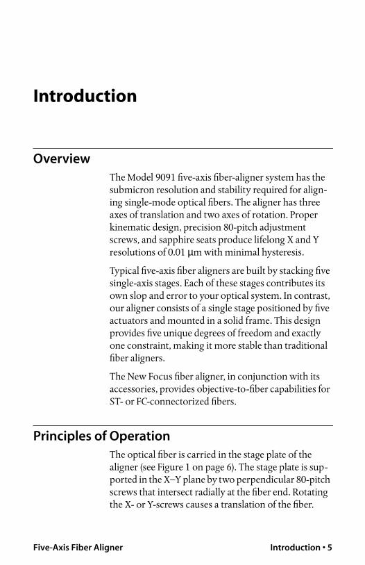
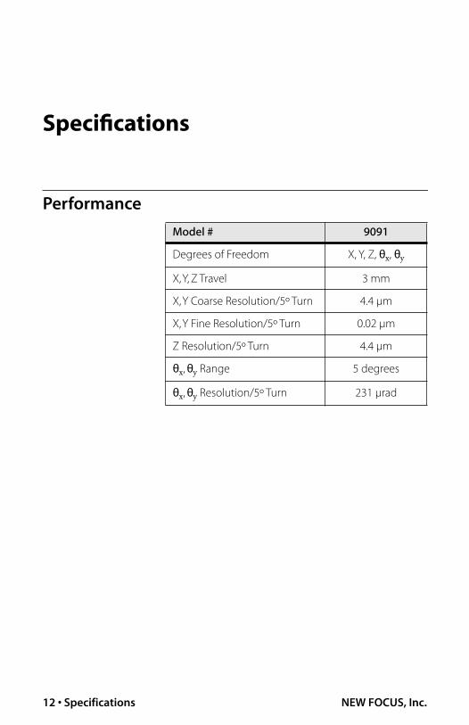
The Model 9091 five-axis fiber-aligner system has the submicron resolution and stability required for align-ing single-mode optical fibers. The aligner has three axes of translation and two axes of rotation. Proper kinematic design, precision 80-pitch adjustment screws, and sapphire seats produce lifelong X and Y resolutions of 0.01
µ
m with minimal hysteresis.
Typical five-axis fiber aligners are built by stacking five single-axis stages. Each of these stages contributes its own slop and error to your optical system. In contrast, our aligner consists of a single stage positioned by five actuators and mounted in a solid frame. This design provides five unique degrees of freedom and exactly one constraint, making it more stable than traditional fiber aligners.
The New Focus fiber aligner, in conjunction with its accessories, provides objective-to-fiber capabilities for ST- or FC-connectorized fibers.
Principles of Operation
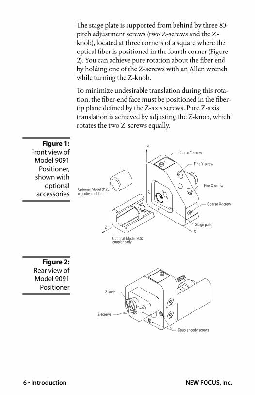
The optical fiber is carried in the stage plate of the aligner (see Figure 1 on page 6). The stage plate is sup-ported in the X–Y plane by two perpendicular 80-pitch screws that intersect radially at the fiber end. Rotating the X- or Y-screws causes a translation of the fiber.
The stage plate is supported from behind by three 80-pitch adjustment screws (two Z-screws and the Z-knob), located at three corners of a square where the optical fiber is positioned in the fourth corner (Figure 2). You can achieve pure rotation about the fiber end by holding one of the Z-screws with an Allen wrench while turning the Z-knob.
To minimize undesirable translation during this rota-tion, the fiber-end face must be positioned in the fiber-tip plane defined by the Z-axis screws. Pure Z-axis translation is achieved by adjusting the Z-knob, which rotates the two Z-screws equally.
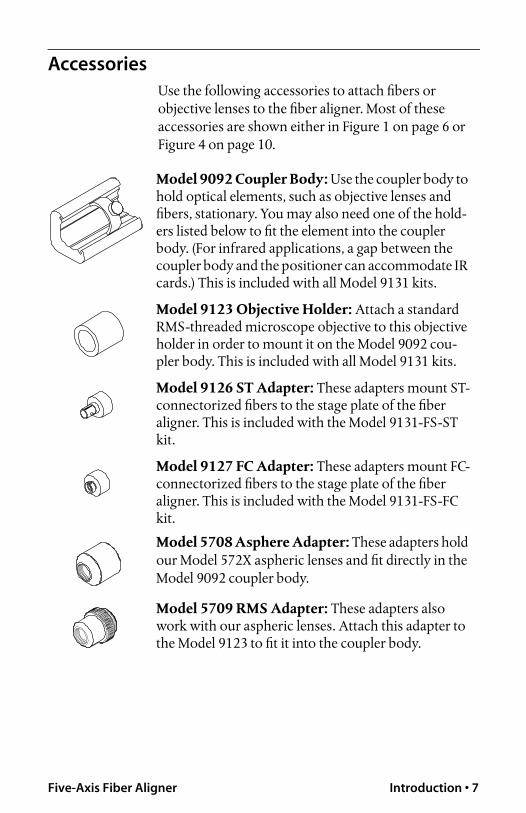
Use the following accessories to attach fibers or objective lenses to the fiber aligner. Most of these accessories are shown either in Figure 1 on page 6 or Figure 4 on page 10.
Model 9092 Coupler Body:
Use the coupler body to hold optical elements, such as objective lenses and fibers, stationary. You may also need one of the hold-ers listed below to fit the element into the coupler body. (For infrared applications, a gap between the coupler body and the positioner can accommodate IR cards.) This is included with all Model 9131 kits.
Model 9123 Objective Holder:
Attach a standard RMS-threaded microscope objective to this objective holder in order to mount it on the Model 9092 cou-pler body. This is included with all Model 9131 kits.
Model 9126 ST Adapter:
These adapters mount ST-connectorized fibers to the stage plate of the fiber aligner. This is included with the Model 9131-FS-ST kit.
Model 9127 FC Adapter:
These adapters mount FC-connectorized fibers to the stage plate of the fiber aligner. This is included with the Model 9131-FS-FC kit.
Model 5708 Asphere Adapter:
These adapters hold our Model 572X aspheric lenses and fit directly in the Model 9092 coupler body.
Model 5709 RMS Adapter:
These adapters also work with our aspheric lenses. Attach this adapter to the Model 9123 to fit it into the coupler body.
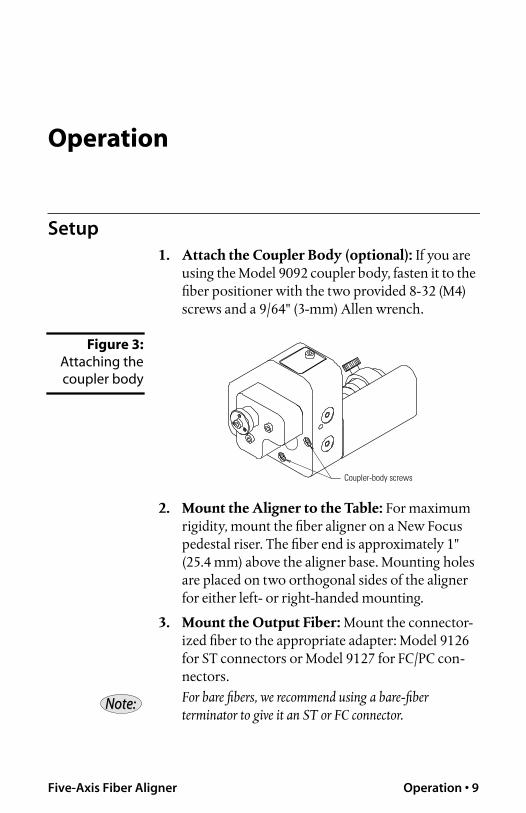
If you are using the Model 9092 coupler body, fasten it to the fiber positioner with the two provided 8-32 (M4) screws and a 9/64" (3-mm) Allen wrench.
Figure 3:
Attaching the
coupler body
2. Mount the Aligner to the Table:
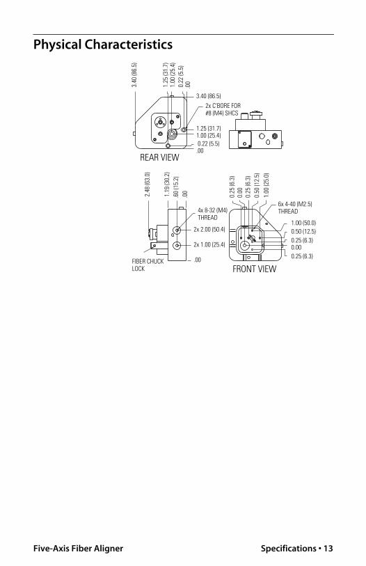
For maximum rigidity, mount the fiber aligner on a New Focus pedestal riser. The fiber end is approximately 1" (25.4 mm) above the aligner base. Mounting holes are placed on two orthogonal sides of the aligner for either left- or right-handed mounting.
3. Mount the Output Fiber:
Mount the connector-ized fiber to the appropriate adapter: Model 9126 for ST connectors or Model 9127 for FC/PC con-nectors.
For bare fibers, we recommend using a bare-fiber terminator to give it an ST or FC connector.
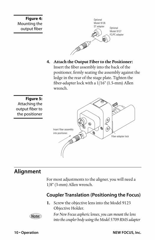
Insert the fiber assembly into the back of the positioner, firmly seating the assembly against the ledge in the rear of the stage plate. Tighten the fiber-adapter lock with a 1/16" (1.5-mm) Allen wrench.
Figure 5:
Attaching theoutput fiber to
the positioner
Alignment
For most adjustments to the aligner, you will need a1/8" (3-mm) Allen wrench.
Coupler Translation (Positioning the Focus)
1.
Screw the objective lens into the Model 9123 Objective Holder.
For New Focus aspheric lenses, you can mount the lens into the coupler body using the Model 5709 RMS adapter
and the Model 9123 objective holder, or using the Model 5708 1" adapter.
2.
Position the holder in the coupler body so that the objective-lens focus is in the fiber-tip plane.
3.
Tighten the thumbscrew to lock the objective into place.
X/Y Translation
The coarse X- and Y-screws each translate the fiber over a 3-mm range with 1-µm resolution. With the fine X- and Y-screws, 8 µm of final tuning can be achieved with a resolution of 0.01 µm.
Z Translation
Turning the Z-knob translates the fiber along the Z-axis of the aligner. This adjustment produces a 1-µm resolution over a 3-mm range.
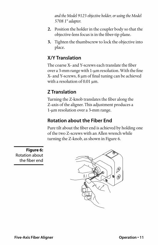
Rotation about the Fiber End
Pure tilt about the fiber end is achieved by holding one of the two Z-screws with an Allen wrench while turning the Z-knob, as shown in Figure 6.
Information and advice about the operation of any New Focus product is available from our applications engineers. For quickest response, ask for “Technical Support” and know the model and serial numbers for your product.
Hours:
8:00–5:00 PST, Monday through Friday (excluding holidays).
We typically respond to faxes and email within one business day.
Service
In the event that your fiber aligner becomes damaged, please contact New Focus for a return authorization number and instructions on shipping the unit back for evaluation and repair.
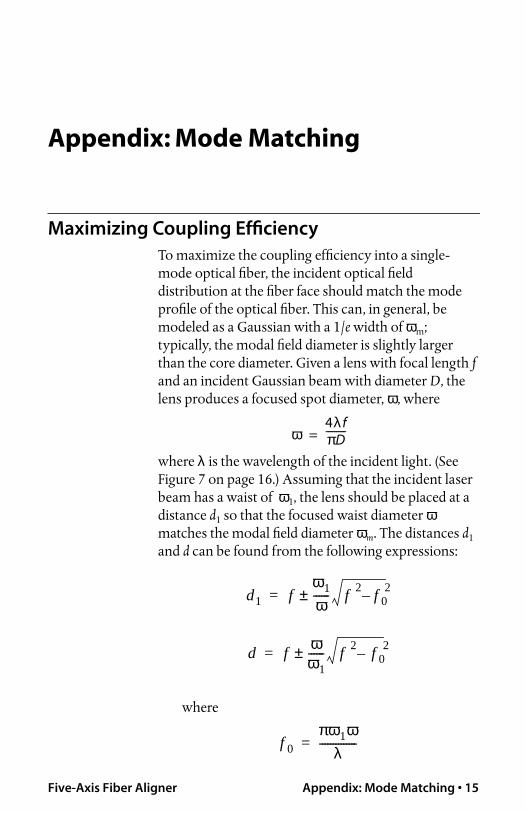
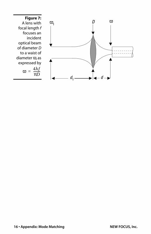
To maximize the coupling efficiency into a single-mode optical fiber, the incident optical field distribution at the fiber face should match the mode profile of the optical fiber. This can, in general, be modeled as a Gaussian with a 1/
e
width of
ω
m
; typically, the modal field diameter is slightly larger than the core diameter. Given a lens with focal length
f
and an incident Gaussian beam with diameter
D
, the lens produces a focused spot diameter,
ω
, where
where
λ
is the wavelength of the incident light. (See Figure 7 on page 16.) Assuming that the incident laser beam has a waist of