78
TECHNICAL REPORT © The Broadband Forum. All rights reserved. TR-370 Fixed Access Network Sharing - Architecture and Nodal Requirements Issue: 1 Issue Date: November 2017
TECHNICAL REPORT
© The Broadband Forum. All rights reserved.
TR-370
Fixed Access Network Sharing - Architecture and Nodal Requirements
Issue: 1
Issue Date: November 2017
Fixed Access Network Sharing - Architecture and Nodal Requirements TR-370 Issue 1
November 2017 © The Broadband Forum. All rights reserved 2 of 78
Notice
The Broadband Forum is a non-profit corporation organized to create guidelines for broadband
network system development and deployment. This Technical Report has been approved by
members of the Forum. This Technical Report is subject to change. This Technical Report is
copyrighted by the Broadband Forum, and all rights are reserved. Portions of this Technical Report
may be copyrighted by Broadband Forum members.
Intellectual Property
Recipients of this Technical Report are requested to submit, with their comments, notification of
any relevant patent claims or other intellectual property rights of which they may be aware that
might be infringed by any implementation of this Technical Report, or use of any software code
normatively referenced in this Technical Report, and to provide supporting documentation.
Terms of Use
1. License
Broadband Forum hereby grants you the right, without charge, on a perpetual, non-exclusive and
worldwide basis, to utilize the Technical Report for the purpose of developing, making, having
made, using, marketing, importing, offering to sell or license, and selling or licensing, and to
otherwise distribute, products complying with the Technical Report, in all cases subject to the
conditions set forth in this notice and any relevant patent and other intellectual property rights of
third parties (which may include members of Broadband Forum). This license grant does not
include the right to sublicense, modify or create derivative works based upon the Technical Report
except to the extent this Technical Report includes text implementable in computer code, in which
case your right under this License to create and modify derivative works is limited to modifying and
creating derivative works of such code. For the avoidance of doubt, except as qualified by the
preceding sentence, products implementing this Technical Report are not deemed to be derivative
works of the Technical Report.
2. NO WARRANTIES
THIS TECHNICAL REPORT IS BEING OFFERED WITHOUT ANY WARRANTY
WHATSOEVER, AND IN PARTICULAR, ANY WARRANTY OF NONINFRINGEMENT IS
EXPRESSLY DISCLAIMED. ANY USE OF THIS TECHNICAL REPORT SHALL BE MADE
ENTIRELY AT THE IMPLEMENTER'S OWN RISK, AND NEITHER THE BROADBAND
FORUM, NOR ANY OF ITS MEMBERS OR SUBMITTERS, SHALL HAVE ANY LIABILITY
WHATSOEVER TO ANY IMPLEMENTER OR THIRD PARTY FOR ANY DAMAGES OF
ANY NATURE WHATSOEVER, DIRECTLY OR INDIRECTLY, ARISING FROM THE USE
OF THIS TECHNICAL REPORT.
3. THIRD PARTY RIGHTS
Without limiting the generality of Section 2 above, BROADBAND FORUM ASSUMES NO
RESPONSIBILITY TO COMPILE, CONFIRM, UPDATE OR MAKE PUBLIC ANY THIRD
PARTY ASSERTIONS OF PATENT OR OTHER INTELLECTUAL PROPERTY RIGHTS
THAT MIGHT NOW OR IN THE FUTURE BE INFRINGED BY AN IMPLEMENTATION OF
THE TECHNICAL REPORT IN ITS CURRENT, OR IN ANY FUTURE FORM. IF ANY SUCH
Fixed Access Network Sharing - Architecture and Nodal Requirements TR-370 Issue 1
November 2017 © The Broadband Forum. All rights reserved 3 of 78
RIGHTS ARE DESCRIBED ON THE TECHNICAL REPORT, BROADBAND FORUM TAKES
NO POSITION AS TO THE VALIDITY OR INVALIDITY OF SUCH ASSERTIONS, OR THAT
ALL SUCH ASSERTIONS THAT HAVE OR MAY BE MADE ARE SO LISTED.
In addition to the notation above, the Forum draws attention to the fact that it is claimed that
compliance with this Specification may involve the use of a patent ("IPR") concerning sections
4.5.1, 4.5.2, 4.5.3. The Forum takes no position concerning the evidence, validity or scope of this
IPR.
The holder of this IPR has assured the Forum that it is willing to License all IPR it owns and any
third party IPR it has the right to sublicense which might be infringed by any implementation of this
Specification to the Forum and those Licensees (Members and non-Members alike) desiring to
implement this Specification. Information may be obtained from:
Trinity College Dublin
College Green
Dublin 02 Ireland
Attention is also drawn to the possibility that some of the elements of this Specification may be the
subject of IPR other than those identified above. The Forum shall not be responsible for identifying
any or all such IPR.
The text of this notice must be included in all copies of this Technical Report.

Fixed Access Network Sharing - Architecture and Nodal Requirements TR-370 Issue 1
November 2017 © The Broadband Forum. All rights reserved 4 of 78
Issue History
Issue Number Approval Date Publication Date Issue Editor Changes
1 27 November
2017
12 January 2018 Bruno Cornaglia, Vodafone Original
Comments or questions about this Broadband Forum Technical Report should be directed to
Editor Bruno Cornaglia Vodafone
Group
Services
SDN and NFV Work
Area Director(s)
George Dobrowski Huawei
Technologies
Co., Ltd.
wei.com
Chris Croot BT [email protected]
Fixed Access Network Sharing - Architecture and Nodal Requirements TR-370 Issue 1
November 2017 © The Broadband Forum. All rights reserved 5 of 78
TABLE OF CONTENTS
EXECUTIVE SUMMARY ................................................................................................................ 9
1 PURPOSE AND SCOPE ......................................................................................................... 10
1.1 PURPOSE .............................................................................................................................. 10 1.2 SCOPE .................................................................................................................................. 10 1.3 BUSINESS CONTEXT ............................................................................................................ 11
2 REFERENCES AND TERMINOLOGY ............................................................................... 12
2.1 CONVENTIONS ..................................................................................................................... 12 2.2 REFERENCES ....................................................................................................................... 12 2.3 DEFINITIONS ........................................................................................................................ 14
2.4 ABBREVIATIONS .................................................................................................................. 14
3 TECHNICAL REPORT IMPACT ......................................................................................... 19
3.1 ENERGY EFFICIENCY ........................................................................................................... 19 3.2 IPV6 .................................................................................................................................... 19
3.3 SECURITY ............................................................................................................................ 19 3.4 PRIVACY .............................................................................................................................. 19
4 ARCHITECTURE AND TOPOLOGIES .............................................................................. 20
4.1 ARCHITECTURE ................................................................................................................... 20 4.2 SHARING MODEL ................................................................................................................. 22
4.3 NETWORK AND USER INTERFACES ...................................................................................... 25 4.4 DEPLOYMENT MODELS ....................................................................................................... 25
4.5 QOS / BANDWIDTH ALLOCATION MODELS ........................................................................... 27
5 SHARING ALTERNATIVES ................................................................................................. 29
5.1 MANAGEMENT SYSTEM ....................................................................................................... 29 5.1.1 Management System Sharing Architecture .................................................................... 30
5.1.2 Centralized Management System ................................................................................... 31
5.1.3 Resource Management ................................................................................................... 31 5.1.4 Management System Sharing Functions ........................................................................ 32
5.2 VIRTUAL NODE SHARING APPROACH .................................................................................. 33 5.2.1 Virtual Access Node ....................................................................................................... 33 5.2.2 Virtual Aggregation Node .............................................................................................. 39
5.2.3 InP Port Mapper ............................................................................................................ 40 5.2.4 Access Network Function as a Service ........................................................................... 44
5.2.5 Relationship to ETSI NFV Architecture ......................................................................... 46 5.2.6 VNO Traffic Encapsulation Models ............................................................................... 48
6 RELATION OF FANS TO THE ETSI NFV ARCHITECTURE ....................................... 53
6.1 FUNCTIONAL DOMAINS ....................................................................................................... 53 6.1.1 NFV Infrastructure (NFVI) Domain .............................................................................. 55 6.1.2 Virtualized Network Functions (VNFs) Domain ............................................................ 56 6.1.3 NFV Management and Orchestration (MANO) Domain ............................................... 57
Fixed Access Network Sharing - Architecture and Nodal Requirements TR-370 Issue 1
November 2017 © The Broadband Forum. All rights reserved 6 of 78
6.2 INTERFACES & REFERENCE POINTS ..................................................................................... 58
6.2.1 NFVI - Virtualized Infrastructure Manager (Nf-Vi) ...................................................... 58
6.2.2 VNF/EM - VNF Manager (Ve-Vnfm) ............................................................................. 58 6.2.3 OSS/BSS - NFV Management and Orchestration (Os-Ma) ........................................... 59 6.2.4 OSS/BSS – Physical Infrastructure ................................................................................ 59 6.2.5 Virtualization Layer - Hardware Resources (Vl-Ha) ..................................................... 59 6.2.6 VNF - NFV Infrastructure (Vn-Nf) ................................................................................. 59
6.2.7 Infrastructure Network Domain - Existing Network (Ex-Nd) ........................................ 59 6.2.8 NFV Infrastructure (Nd-Nd) ........................................................................................... 59
6.3 NFV MANO ....................................................................................................................... 60
7 TECHNICAL REQUIREMENTS .......................................................................................... 62
7.1 NETWORK REQUIREMENTS .................................................................................................. 62
7.1.1 Common Requirements .................................................................................................. 62 7.1.2 Access Node .................................................................................................................... 62
7.1.3 Aggregation Node .......................................................................................................... 62 7.2 FUNCTIONAL NODE REQUIREMENTS ................................................................................... 63
7.2.1 Common Requirements .................................................................................................. 63 7.2.2 Access Node .................................................................................................................... 63 7.2.3 Aggregation Node .......................................................................................................... 64
7.3 CENTRALIZED MANAGEMENT SYSTEM REQUIREMENTS ...................................................... 64
8 OAM AND OTHER OPERATIONAL ASPECTS ............................................................... 66
8.1 ETHERNET OAM ................................................................................................................. 66 8.2 OTHER OPERATIONAL ASPECTS .......................................................................................... 68
8.2.1 Customer Relationship Management ............................................................................. 68
8.2.2 Service Management and Operations ............................................................................ 69
8.2.3 Resource Management and Operations ......................................................................... 69
9 PRIVACY AND SECURITY .................................................................................................. 71
APPENDIX I. ACCESS TECHNOLOGIES (INFORMATIVE) ............................................. 73
Fixed Access Network Sharing - Architecture and Nodal Requirements TR-370 Issue 1
November 2017 © The Broadband Forum. All rights reserved 7 of 78
List of Figures
Figure 1 – Integrated Fixed Access Network approach ..................................................................... 21 Figure 2 – FANS Architecture scheme derived from TR-101 [2] and TR-178 [3] .......................... 22 Figure 3 – Virtual Access Network concept ...................................................................................... 23 Figure 4 – FANS Physical Access Node Representation ................................................................... 24 Figure 5 – FANS Chained Access Node Representation ................................................................... 24
Figure 6 – FANS Interface Sharing .................................................................................................... 25 Figure 7 – Interconnectivity Reference Architecture ......................................................................... 25 Figure 8 – Reference Architecture and Protocol Stack Note: PPP/PPPoE are optional .................... 26 Figure 9 – L2 NSP Wholesale Model (TR-178 [3]) ........................................................................... 26 Figure 10 – Management System Overview ...................................................................................... 29
Figure 11 – Abstraction / adaptation layer concept. ........................................................................... 30
Figure 12 – Deployment scenarios for Virtual Access Node Functions ............................................ 33 Figure 13 – Virtual Access Node Model ............................................................................................ 34
Figure 14 – vAN inside the Equipment .............................................................................................. 36
Figure 15 – vAN in the Cloud ............................................................................................................ 36 Figure 16 – vAN Automated Abstraction .......................................................................................... 37 Figure 17 – Detailed Message Flow for the vAN Automated Abstraction ........................................ 38
Figure 18 – Network Layers ............................................................................................................... 39 Figure 19 – Deployment scenarios for Virtual Aggregation Node Functions ................................... 39
Figure 20 – InP Port Mapper for Dedicated ONU ............................................................................. 40 Figure 21 – InP Port Mapper for Shared ONU .................................................................................. 41 Figure 22 – Customer Migration in FANS ......................................................................................... 41
Figure 23 – Virtual Port State Machine ............................................................................................. 43 Figure 24 – Virtual Port State/Status of Customer Migration in FANS ............................................ 43
Figure 25 – VNO Block Traffic when MAC Spoofing is Identified ................................................. 44 Figure 26 - Access Network Function Virtualization and Allocation ................................................ 45
Figure 27 – Applicability of ETSI NFV architecture for Fixed Access Network Sharing ................ 46 Figure 28 – End-to-end VLAN schema for FANS ............................................................................ 49
Figure 29 – Q-in-Q-in-Q frame .......................................................................................................... 49 Figure 30 – Q-in-Q-in-Q VLAN frame detail .................................................................................... 50 Figure 31 – End-to-end MPLS schema for FANS ............................................................................. 51
Figure 32 – End-to-end VXLAN schema for FANS .......................................................................... 51 Figure 33 – VXLAN frame format .................................................................................................... 52 Figure 34 – High-Level NFV Framework .......................................................................................... 53
Figure 35 – NFV reference Architectural Framework and identification of NFVI Domains [13] .... 54 Figure 36 – Virtual Access Node Model ............................................................................................ 55
Figure 37 – Comparing Virtualized Network Infrastructure domains ............................................... 56 Figure 38 – Comparing Management Systems domains .................................................................... 57 Figure 39 – Network Domain Reference Point Architecture [16] ..................................................... 58 Figure 40 – Virtual Access Node model: Centralized Management System roles ............................ 60 Figure 41 – Extension of TR-101 [2] to FANS: InP OAM ................................................................ 67
Figure 42 – Extension of TR-101 [2] to FANS: VNO OAM ............................................................. 67 Figure 43 – eTOM CRM Processes ................................................................................................... 68 Figure 44 – eTOM SM&O Processes ................................................................................................ 69

Fixed Access Network Sharing - Architecture and Nodal Requirements TR-370 Issue 1
November 2017 © The Broadband Forum. All rights reserved 8 of 78
Figure 45 – eTOM RM&O Processes ................................................................................................ 70
Figure 46 – FTTx Access Network Architecture ............................................................................... 73
Figure 47 – FANS 1:1 VLAN Architecture Example ........................................................................ 74 Figure 48 – FANS N:1 VLAN Architecture Example ....................................................................... 75 Figure 49 – FANS TLS VLAN Architecture Example ...................................................................... 76 Figure 50 – Customers management in FANS FTTC/FTTdp/FTTB architectures ........................... 77 Figure 51 – Customers management in FANS FTTH architecture .................................................... 77
List of Tables
Table 1 – Actors & Involved Processes: CRM .................................................................................. 68 Table 2 – Actors & Involved Processes: SM&O ............................................................................... 69
Table 3 – Actors & Involved Processes: RM&O ............................................................................... 70

Fixed Access Network Sharing - Architecture and Nodal Requirements TR-370 Issue 1
November 2017 © The Broadband Forum. All rights reserved 9 of 78
Executive Summary
This Technical Report specifies technical aspects associated with Fixed Access Network Sharing
(FANS) that involve the access network (including access nodes and aggregation nodes). It focuses
on the cases of Passive Optical Network (PON) and DSL and G. fast access technologies.
FANS present business opportunities supporting, the evolution of the fixed access network to enable
new, dynamic service offerings, aligned with the Forum’s Broadband 20/20 vision, and business
relationships. This Technical Report identifies a new type of Virtual Network Operator (VNO), while
specifying the technical requirements associated with both the VNO and the Infrastructure network
Provider (InP).
This Technical Report, based on TR-101 [2], TR-178 [3] and TR-156 [4], documents a set of
architectures for sharing multi-service broadband access networks, implemented using legacy
equipment or based on ETSI NFV virtualization standards. Starting from the above architectural
models, this Technical Report defines topologies, deployment scenarios and specific requirements
needed to successfully deploy a shared access network.
This Technical Report defines two models that both include a centralized management system capable
of supporting a multi-vendor environment, with the goal of maintaining backwards compatibility in
a shared access network infrastructure. The centralized management system is in charge of managing
the network sharing and the above models are differentiated based on the operating methods.
The first solution relies on the centralized management system to perform the network slicing of
existing (legacy) or new network equipment at the management system level (not directly in the
equipment itself), while the second solution implements slicing on the equipment itself and also can
use virtualization as described by ETSI NFV standards. The latter is also capable of coordinating the
virtual Access Node (vAN) and virtual Aggregation Nodes (vAggN) instances of the different VNOs.
Finally the document also includes the OAM, privacy and security considerations necessary to
support multi-operator access sharing.

Fixed Access Network Sharing - Architecture and Nodal Requirements TR-370 Issue 1
November 2017 © The Broadband Forum. All rights reserved 10 of 78
1 Purpose and Scope
1.1 Purpose
“FANS - Architecture and Nodal Requirements” specifies the technical aspects associated with Fixed
Access Network Sharing (FANS) that involve the access network, including both access and
aggregation nodes. Slicing logically partitions and isolates network resources among Virtual Network
Operators (VNOs). FANS Technical Report covers Passive Optical Network (PON) and DSL and
G.fast networks, addressing typical infrastructures, topologies and deployment scenarios.
This Technical Report specifies technical aspects related to the migration of TR-101, TR-178, and
TR-156 based architectures towards a shared, broadband access network that supports slicing for
multi-tenant operation. Functionalities over and above TR-178 are identified. This includes
specifying which access node functions would continue to be managed by the Infrastructure Provider
(InP) and which would be managed by a VNO. Access and backhaul interface sharing may require
additions to the required transport encapsulations, QoS and OAM capabilities.
“FANS - Architecture and Nodal Requirements” defines two different models for resources sharing
or slicing:
• Management System based, which performs network slicing at management system level and
not directly in the equipment itself.
• Virtual Access Node based, which extends the capabilities of physical access and aggregation
nodes to support multiple, virtual partitions, each containing ports and forwarding resources
directly managed by a VNO.
This Technical Report also identifies the relationship between FANS and the ETSI and BBF TR-359
NFV architecture.
For both the Management System and Virtual Access Node approaches, this Technical Report defines
the architectural options and requirements intended for implementation on existing TR-101/TR-178
access networks through software upgrade, as well as requirements that would only apply to new
access nodes.
Finally the document considers the security and privacy aspects necessary to support multi-operator
access sharing/slicing.
1.2 Scope
The scope of “FANS - Architecture and Nodal Requirements” is to address Fixed Access Network
Sharing with an analysis of the access network, in terms of the following functions:
• Physical and Logical Network Architecture
• Technical and Functional Node Requirements
• User/Network Interfaces (T, U / V, A10)
• Layer 2 interconnection

Fixed Access Network Sharing - Architecture and Nodal Requirements TR-370 Issue 1
November 2017 © The Broadband Forum. All rights reserved 11 of 78
• Management Interfaces
• Virtual Node Framework and Interfaces
• Virtualization Techniques
• OAM and other Operational Aspects
• Privacy and Security
1.3 Business Context
The primary FANS scenario is related to VNOs and InP being different entities. In addition, this
Technical Report specification can also apply to a network operator that wants to slice its own access
network in order to offer services to different market segments (e.g., for residential or enterprise
markets), and wants to be able to use a vertical structure within its organization for aspects related to
the customers, services and resources.

Fixed Access Network Sharing - Architecture and Nodal Requirements TR-370 Issue 1
November 2017 © The Broadband Forum. All rights reserved 12 of 78
2 References and Terminology
2.1 Conventions
In this Technical Report, several words are used to signify the requirements of the specification.
These words are always capitalized. More information can be found be in RFC 2119 [1].
MUST This word, or the term “REQUIRED”, means that the definition is an
absolute requirement of the specification.
MUST NOT This phrase means that the definition is an absolute prohibition of the
specification.
SHOULD This word, or the term “RECOMMENDED”, means that there could
exist valid reasons in particular circumstances to ignore this item, but
the full implications need to be understood and carefully weighed
before choosing a different course.
SHOULD NOT This phrase, or the phrase "NOT RECOMMENDED" means that there
could exist valid reasons in particular circumstances when the
particular behavior is acceptable or even useful, but the full
implications need to be understood and the case carefully weighed
before implementing any behavior described with this label.
MAY This word, or the term “OPTIONAL”, means that this item is one of
an allowed set of alternatives. An implementation that does not
include this option MUST be prepared to inter-operate with another
implementation that does include the option.
2.2 References
The following references are of relevance to this Technical Report. At the time of publication, the
editions indicated were valid. All references are subject to revision; users of this Technical Report
are therefore encouraged to investigate the possibility of applying the most recent edition of the
references listed below.
A list of currently valid Broadband Forum Technical Reports is published at
www.broadband-forum.org.
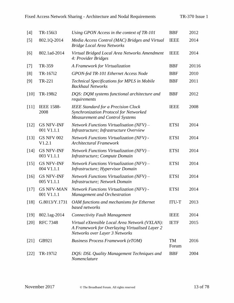
Document Title Source Year
[1] RFC 2119 Key words for use in RFCs to Indicate
Requirement Levels
IETF 1997
[2] TR-101i2 Migration to Ethernet Based DSL Aggregation BBF 2011
[3] TR-178 Multi-service Broadband Network Architecture
and Nodal Requirements
BBF 2014
Fixed Access Network Sharing - Architecture and Nodal Requirements TR-370 Issue 1
November 2017 © The Broadband Forum. All rights reserved 13 of 78
[4] TR-156i3 Using GPON Access in the context of TR-101 BBF 2012
[5] 802.1Q-2014 Media Access Control (MAC) Bridges and Virtual
Bridge Local Area Networks
IEEE 2014
[6] 802.1ad-2014 Virtual Bridged Local Area Networks Amendment
4: Provider Bridges
IEEE 2014
[7] TR-359 A Framework for Virtualization BBF 20116
[8] TR-167i2 GPON-fed TR-101 Ethernet Access Node BBF 2010
[9] TR-221 Technical Specifications for MPLS in Mobile
Backhaul Networks
BBF 2011
[10] TR-198i2 DQS: DQM systems functional architecture and
requirements
BBF 2012
[11] IEEE 1588-
2008
IEEE Standard for a Precision Clock
Synchronization Protocol for Networked
Measurement and Control Systems
IEEE 2008
[12] GS NFV-INF
001 V1.1.1
Network Functions Virtualisation (NFV) –
Infrastructure; Infrastructure Overview
ETSI 2014
[13] GS NFV 002
V1.2.1
Network Functions Virtualization (NFV) -
Architectural Framework
ETSI 2014
[14] GS NFV-INF
003 V1.1.1
Network Functions Virtualization (NFV) –
Infrastructure; Compute Domain
ETSI 2014
[15] GS NFV-INF
004 V1.1.1
Network Functions Virtualization (NFV) –
Infrastructure; Hypervisor Domain
ETSI 2014
[16] GS NFV-INF
005 V1.1.1
Network Functions Virtualization (NFV) –
Infrastructure; Network Domain
ETSI 2014
[17] GS NFV-MAN
001 V1.1.1
Network Functions Virtualization (NFV) -
Management and Orchestration
ETSI 2014
[18] G.8013/Y.1731 OAM functions and mechanisms for Ethernet
based networks
ITU-T 2013
[19] 802.1ag-2014 Connectivity Fault Management IEEE 2014
[20] RFC 7348 Virtual eXtensible Local Area Network (VXLAN):
A Framework for Overlaying Virtualised Layer 2
Networks over Layer 3 Networks
IETF 2015
[21] GB921 Business Process Framework (eTOM) TM
Forum
2016
[22] TR-197i2 DQS: DSL Quality Management Techniques and
Nomenclature
BBF 2004
Fixed Access Network Sharing - Architecture and Nodal Requirements TR-370 Issue 1
November 2017 © The Broadband Forum. All rights reserved 14 of 78
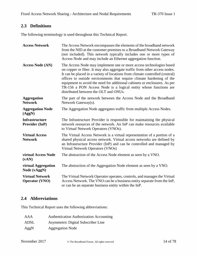
2.3 Definitions
The following terminology is used throughout this Technical Report.
Access Network The Access Network encompasses the elements of the broadband network
from the NID at the customer premises to a Broadband Network Gateway
(not included). This network typically includes one or more types of
Access Node and may include an Ethernet aggregation function.
Access Node (AN) The Access Node may implement one or more access technologies based
on copper or fiber. It may also aggregate traffic from other access nodes.
It can be placed in a variety of locations from climate controlled (central)
offices to outside environments that require climate hardening of the
equipment to avoid the need for additional cabinets or enclosures. As per
TR-156 a PON Access Node is a logical entity whose functions are
distributed between the OLT and ONUs.
Aggregation
Network
The part of the network between the Access Node and the Broadband
Network Gateway(s).
Aggregation Node
(AggN)
The Aggregation Node aggregates traffic from multiple Access Nodes.
Infrastructure
Provider (InP)
The Infrastructure Provider is responsible for maintaining the physical
network resources of the network. An InP can make resources available
to Virtual Network Operators (VNOs).
Virtual Access
Network
The Virtual Access Network is a virtual representation of a portion of a
shared physical access network. Virtual access networks are defined by
an Infrastructure Provider (InP) and can be controlled and managed by
Virtual Network Operators (VNOs)
virtual Access Node
(vAN)
The abstraction of the Access Node element as seen by a VNO.
virtual Aggregation
Node (vAggN)
The abstraction of the Aggregation Node element as seen by a VNO.
Virtual Network
Operator (VNO)
The Virtual Network Operator operates, controls, and manages the Virtual
Access Network. The VNO can be a business entity separate from the InP,
or can be an separate business entity within the InP.
2.4 Abbreviations
This Technical Report uses the following abbreviations:
AAA Authentication Authorization Accounting
ADSL Asymmetric Digital Subscriber Line
AggN Aggregation Node
Fixed Access Network Sharing - Architecture and Nodal Requirements TR-370 Issue 1
November 2017 © The Broadband Forum. All rights reserved 15 of 78
AN Access Node
API Application Programming Interface
ATM Asynchronous Transfer Mode
BGP Border Gateway Protocol
BNG Broadband Network Gateway
BSS Business Support System
CO Central Office
CoS Class of Service
CPE Customer Premises Equipment
CPU Central Processing Unit
DCF Data Collection Function
DDoS Distributed Denial of Service
DHCP Dynamic Host Configuration Protocol
DQM DSL Quality Management
DQS DSL Quality Suite
DSL Digital Subscriber Line
DSLAM Digital Subscriber Line Access Multiplexer
DSM Dynamic Spectrum Management
DWDM Dense Wavelength Division Multiplexing
EM Element Manager
EMS Element Management System
E-NNI External Network to Network Interface
ETSI European Telecommunications Standards Institute
E2E End To End
eTOM Enhanced Telecom Operations Map
FANS Fixed Access Network Sharing
FTTB Fiber To The Building
FTTC Fiber To The Curb/Cabinet
FTTdp Fiber To The Distribution Point
FTTH Fiber To The Home
FTTx Fiber To The x (generalization for several types of fiber deployment)
GEM GPON Encapsulation Method
GPON Gigabit Passive Optical Network
IEEE Institute of Electrical and Electronics Engineers
IETF Internet Engineering Task Force
IGMP Internet Group Management Protocol

Fixed Access Network Sharing - Architecture and Nodal Requirements TR-370 Issue 1
November 2017 © The Broadband Forum. All rights reserved 16 of 78
IMS IP Multimedia Subsystem
I-NNI Internal Network to Network Interface
InP Infrastructure Provider
IP Internet Protocol
IPv4 Internet Protocol version 4
IPv6 Internet Protocol version 6
IPTV Internet Protocol Television
ISG Industrial Study Group
ITU-T International Telecommunication Union – Telecommunication Standardization
Bureau
L2 Layer 2
L2TP L2 Tunneling Protocol
L3 Layer 3
LAN Local Area Network
LSP Label Switched Path
MAC Medium Access Control
MANO Management & Orchestration
MDF Main Distribution Frame
MEP Maintenance End Point
MIP Maintenance Intermediate Point
MPLS Multi-Protocol Label Switching
MS Management System
NBI Northbound Interface
NERG Network Enhanced Residential Gateway
NETCONF Network Configuration Protocol
NFV Network Functions Virtualization
NFVI Network Function Virtualization Infrastructure
NFVO NFV Orchestrator
NGN Next Generation Network
NG-PON Next Generation Passive Optical Network
NIC Network Interface Card
NID Network Interface Device
NMS Network Management System
NNI Network-to-Network Interface
NSP Network Service Provider
NT Network Termination

Fixed Access Network Sharing - Architecture and Nodal Requirements TR-370 Issue 1
November 2017 © The Broadband Forum. All rights reserved 17 of 78
NTU Network Terminal Unit
NVE Network Virtual Element
OAM Operation, Administration and Maintenance
ODN Optical Distribution Node
OLT Optical Line Termination
ONT Optical Network Terminator
ONU Optical Network Unit
OSS Operational Support System
O-Tag Operator Tag
O-VLAN Operator VLAN
PABX Private Automatic Branch eXchange
pAN Physical Access Node
PCE Power Control Entity
PCP Priority Code Point
PE Provider Edge
PHY Physical
PNF Physical Network Function
PON Passive Optical Network
POP Point Of Presence
PPP Point-to-Point Protocol
PPPoE Point-to-Point Protocol over Ethernet
PtP Point-to-Point
PTP Precision Timing Protocol
QoS Quality of Service
RG Residential Gateway
SBI Southbound Interface
SDH Synchronous Digital Hierarchy
SDN Software Defined Networking
SHDSL Single-Pair High-Speed DSL
SLA Service Level Agreement
SNI Service Node Interface
SW Switch
TE Traffic Engineering
TLS Transparent LAN Services
TR Technical Report
UNI User-to-Network Interface
Fixed Access Network Sharing - Architecture and Nodal Requirements TR-370 Issue 1
November 2017 © The Broadband Forum. All rights reserved 18 of 78
vAggN Virtual Aggregation Node
vAN virtual Access Node
vBNG Virtual Broadband Network Gateway
VDSL Very High-Speed Digital Subscriber Line
VIM Virtual Infrastructure Manager
VLAN Virtual LAN
VNF Virtual Network Function
VNFM Virtual Network Function Management
VNI VXLAN Network Identifier
VNO Virtual Network Operator
VPN Virtual Private Network
VTEP VXLAN Tunnel End Point
vRG Virtual Residential Gateway
VXLAN Virtual Extensible LAN
WDM Wavelength Division Multiplexing
xDSL Any Digital Subscriber Line Service

Fixed Access Network Sharing - Architecture and Nodal Requirements TR-370 Issue 1
November 2017 © The Broadband Forum. All rights reserved 19 of 78
3 Technical Report Impact
3.1 Energy Efficiency
FANS introduces the concept of Fixed Access Network Sharing that splits the physical access
network into a number of virtual access networks, which can be shared by multiple Virtual Network
Operators (VNOs). By allowing multiple VNOs to share a single physical network infrastructure,
FANS enables energy efficiency improvements in the network.
3.2 IPv6
FANS uses current specifications of IPv6 and no specific impact is foreseen. Sharing methods in this
document are at Layer 2, so each VNO can have its own specific IP range, both IPv4 and IPv6.
3.3 Security
Sharing the same infrastructure among different operators can create issues of security. In order to
address these, it is necessary to have robust methods for isolating the resources, including data, control
and management planes, of all operators. The document provides recommendations to address
security issues.
3.4 Privacy
Sharing the same infrastructure between different operators can create issues of customer privacy. It
is necessary to define methods for isolating the control and management planes of all operators as
well as customers’ networks and information. The document will provide recommendations to
address privacy issues.

Fixed Access Network Sharing - Architecture and Nodal Requirements TR-370 Issue 1
November 2017 © The Broadband Forum. All rights reserved 20 of 78
4 Architecture and Topologies
The accelerating demand for capacity and the need for new business and service models is forcing
network operators to seek cost-effective ways to modernize their networks.
The traditional model of single ownership of all the physical network elements and network layers by
network operators is beginning to be challenged. Competing operators may now wish to cooperate in
network-sharing schemes.
The basic assertion is that, with advances in technology, access networks can be shared to a greater
extent than they currently are. The current methods for access network sharing (e.g., Bitstream),
where service packages are only differentiated by bandwidth, limit the ability of VNOs to provide
richer service differentiation.
In FANS, a physical Access Network owned by an Infrastructure Provider (InP) can be shared by
multiple Virtual Network Operators (VNOs). Each VNO operates and manages a virtual slice of the
physical network to provide customized services. Each slice spans the physical network between the
following reference points as defined in TR-101[2]/TR-178[3]/TR-156[4]:
• U/U1 between shared network and CPE
• A10 (E-NNI L2) between shared network and BNG
Neither the CPE nor the BNG are part of the Virtual Access Network – instead, each of these network
elements is owned by the VNO.
FANS defines two different models for resources sharing:
• Management System [section 5.1]
• Virtual Node [section 5.2]
In the Management System model, network slicing is performed in the management plane. A
centralized management system controls the physical network and provides a management view to
each VNO of its own network slice. The centralized management system includes an abstraction layer
that maps each virtual network to the physical network. In this model, the devices in the physical
network are unaware of the virtual slices, and each VNO is unaware of resources outside its own
slice. This model is well suited to access networks which still have legacy devices.
In the Virtual Access Node model, network slicing is performed in both the management and data
planes. In the Virtual Access Network, each VNO controls virtual Access Nodes (vANs) as well as
potentially other virtualized functions in the data plane. This model allows a broader variety of
functions to be supported by each VNO.
4.1 Architecture
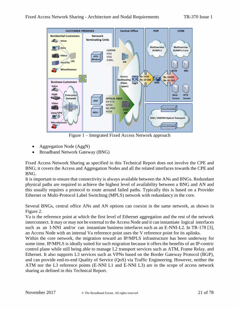
Figure 1 shows a high level perspective of the access network. The main network elements in a fixed
broadband network are:
• Customer Premises Equipment (CPE)
• Access Node (AN)
Fixed Access Network Sharing - Architecture and Nodal Requirements TR-370 Issue 1
November 2017 © The Broadband Forum. All rights reserved 21 of 78
Figure 1 – Integrated Fixed Access Network approach
• Aggregation Node (AggN)
• Broadband Network Gateway (BNG)
Fixed Access Network Sharing as specified in this Technical Report does not involve the CPE and
BNG; it covers the Access and Aggregation Nodes and all the related interfaces towards the CPE and
BNG.
It is important to ensure that connectivity is always available between the ANs and BNGs. Redundant
physical paths are required to achieve the highest level of availability between a BNG and AN and
this usually requires a protocol to route around failed paths. Typically this is based on a Provider
Ethernet or Multi-Protocol Label Switching (MPLS) network with redundancy in the core.
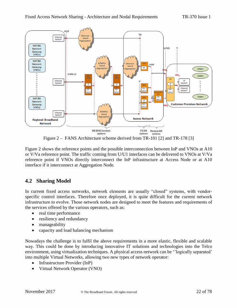
Several BNGs, central office ANs and AN options can coexist in the same network, as shown in
Figure 2.
Va is the reference point at which the first level of Ethernet aggregation and the rest of the network
interconnect. It may or may not be external to the Access Node and it can instantiate logical interfaces
such as an I-NNI and/or can instantiate business interfaces such as an E-NNI-L2. In TR-178 [3],
an Access Node with an internal Va reference point uses the V reference point for its uplinks.
Within the core network, the migration toward an IP/MPLS infrastructure has been underway for
some time. IP/MPLS is ideally suited for such migration because it offers the benefits of an IP-centric
control plane while still being able to manage L2 transport services such as ATM, Frame Relay, and
Ethernet. It also supports L3 services such as VPNs based on the Border Gateway Protocol (BGP),
and can provide end-to-end Quality of Service (QoS) via Traffic Engineering. However, neither the
ATM nor the L3 reference points (E-NNI L1 and E-NNI L3) are in the scope of access network
sharing as defined in this Technical Report.
Fixed Access Network Sharing - Architecture and Nodal Requirements TR-370 Issue 1
November 2017 © The Broadband Forum. All rights reserved 22 of 78
Figure 2 – FANS Architecture scheme derived from TR-101 [2] and TR-178 [3]
Figure 2 shows the reference points and the possible interconnection between InP and VNOs at A10
or V/Va reference point. The traffic coming from U/U1 interfaces can be delivered to VNOs at V/Va
reference point if VNOs directly interconnect the InP infrastructure at Access Node or at A10
interface if it interconnect at Aggregation Node.
4.2 Sharing Model
In current fixed access networks, network elements are usually “closed” systems, with vendor-
specific control interfaces. Therefore once deployed, it is quite difficult for the current network
infrastructure to evolve. Those network nodes are designed to meet the features and requirements of
the services offered by the various operators, such as:
• real time performance
• resiliency and redundancy
• manageability
• capacity and load balancing mechanism
Nowadays the challenge is to fulfil the above requirements in a more elastic, flexible and scalable
way. This could be done by introducing innovative IT solutions and technologies into the Telco
environment, using virtualization techniques. A physical access network can be ‘’logically separated’
into multiple Virtual Networks, allowing two new types of network operator:
• Infrastructure Provider (InP)
• Virtual Network Operator (VNO)
Fixed Access Network Sharing - Architecture and Nodal Requirements TR-370 Issue 1
November 2017 © The Broadband Forum. All rights reserved 23 of 78
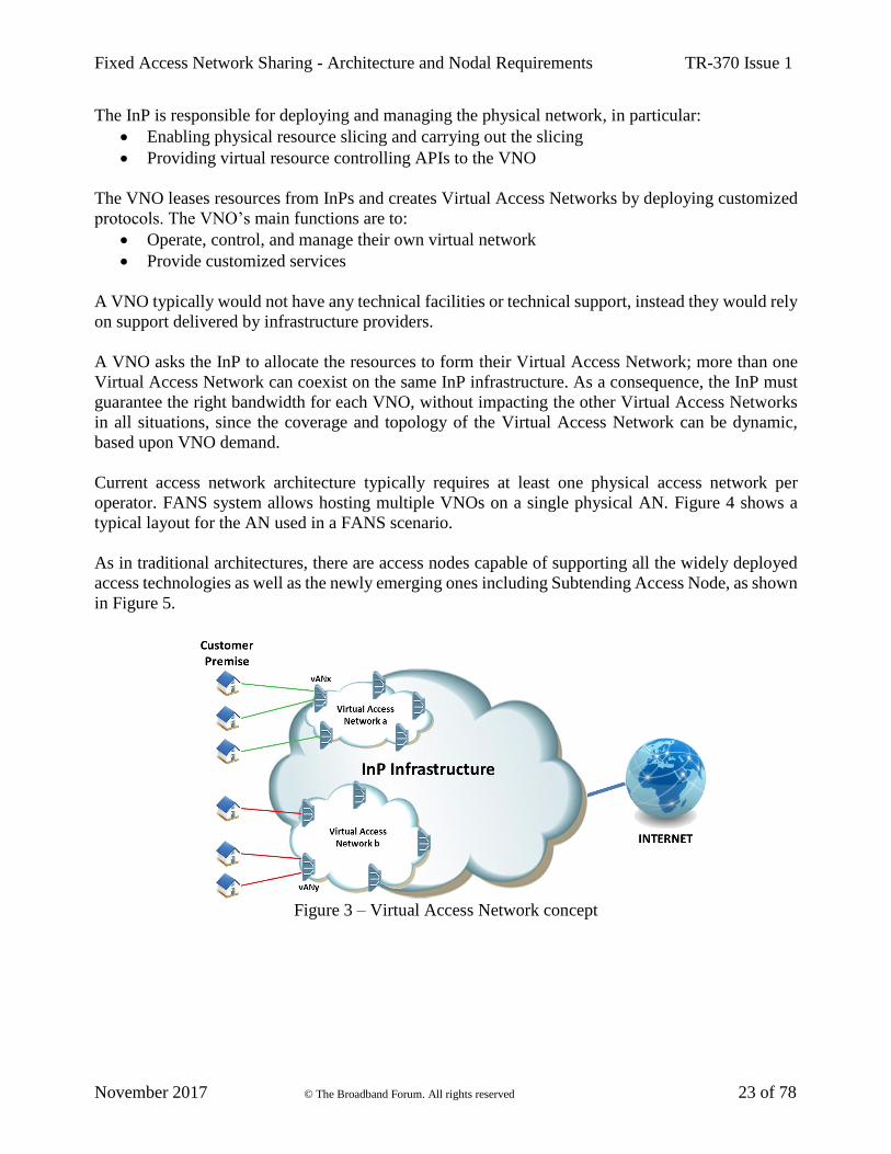
The InP is responsible for deploying and managing the physical network, in particular:
• Enabling physical resource slicing and carrying out the slicing
• Providing virtual resource controlling APIs to the VNO
The VNO leases resources from InPs and creates Virtual Access Networks by deploying customized
protocols. The VNO’s main functions are to:
• Operate, control, and manage their own virtual network
• Provide customized services
A VNO typically would not have any technical facilities or technical support, instead they would rely
on support delivered by infrastructure providers.
A VNO asks the InP to allocate the resources to form their Virtual Access Network; more than one
Virtual Access Network can coexist on the same InP infrastructure. As a consequence, the InP must
guarantee the right bandwidth for each VNO, without impacting the other Virtual Access Networks
in all situations, since the coverage and topology of the Virtual Access Network can be dynamic,
based upon VNO demand.
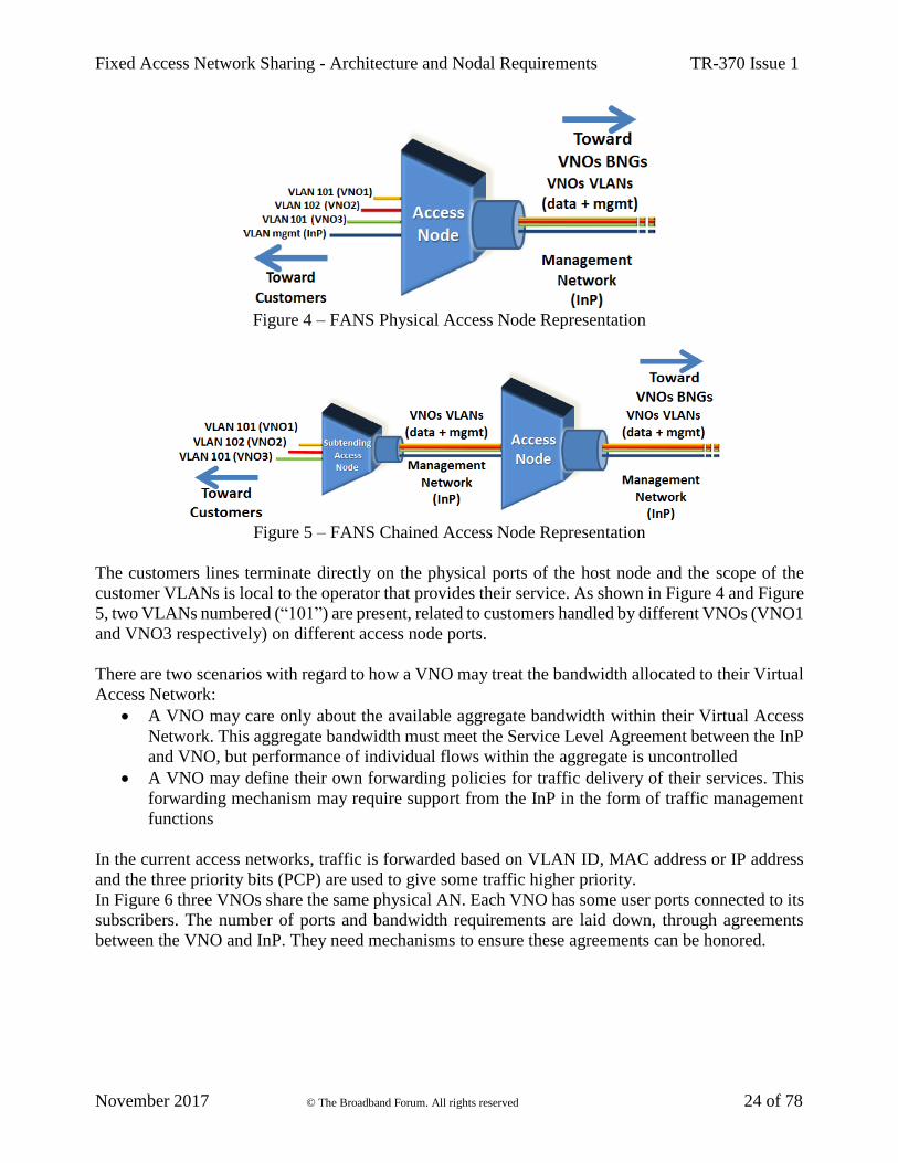
Current access network architecture typically requires at least one physical access network per
operator. FANS system allows hosting multiple VNOs on a single physical AN. Figure 4 shows a
typical layout for the AN used in a FANS scenario.
As in traditional architectures, there are access nodes capable of supporting all the widely deployed
access technologies as well as the newly emerging ones including Subtending Access Node, as shown
in Figure 5.
Figure 3 – Virtual Access Network concept
Fixed Access Network Sharing - Architecture and Nodal Requirements TR-370 Issue 1
November 2017 © The Broadband Forum. All rights reserved 24 of 78
Figure 4 – FANS Physical Access Node Representation
Figure 5 – FANS Chained Access Node Representation
The customers lines terminate directly on the physical ports of the host node and the scope of the
customer VLANs is local to the operator that provides their service. As shown in Figure 4 and Figure
5, two VLANs numbered (“101”) are present, related to customers handled by different VNOs (VNO1
and VNO3 respectively) on different access node ports.
There are two scenarios with regard to how a VNO may treat the bandwidth allocated to their Virtual
Access Network:
• A VNO may care only about the available aggregate bandwidth within their Virtual Access
Network. This aggregate bandwidth must meet the Service Level Agreement between the InP
and VNO, but performance of individual flows within the aggregate is uncontrolled
• A VNO may define their own forwarding policies for traffic delivery of their services. This
forwarding mechanism may require support from the InP in the form of traffic management
functions
In the current access networks, traffic is forwarded based on VLAN ID, MAC address or IP address
and the three priority bits (PCP) are used to give some traffic higher priority.
In Figure 6 three VNOs share the same physical AN. Each VNO has some user ports connected to its
subscribers. The number of ports and bandwidth requirements are laid down, through agreements
between the VNO and InP. They need mechanisms to ensure these agreements can be honored.

Fixed Access Network Sharing - Architecture and Nodal Requirements TR-370 Issue 1
November 2017 © The Broadband Forum. All rights reserved 25 of 78
Figure 6 – FANS Interface Sharing
4.3 Network and User Interfaces
As shown in the Figure 3, the Ethernet network infrastructure on which FANS is based, spreads from
the A10 (ENNI-L2) reference point to the U/U1 reference point. Briefly:
• A10 (or ENNI-L2) interface is the demarcation point between the access network and VNO
network. This interface supports services to both residential and business customers and it can
also handle multiple QoS policies. Note that in some cases A10 is placed at an Access Node,
in which case it is also the V/Va reference point.
• U/U1 is located at the subscriber premise between the Access Node and the residential or
routing gateway for residential or business services.
4.4 Deployment Models
Nowadays, the interconnectivity between a VNO network and the InP infrastructure can be defined
at different levels, using different technologies:
• at AN (Ethernet)
• at Local PoP (Ethernet)
• at Regional PoP (Ethernet or IP, with the latter not in FANS scope)
• at National PoP (IP, not in FANS scope)
Figure 7 – Interconnectivity Reference Architecture
Figure 7 shows that the Ethernet interconnectivity is typically at Local or Regional level, while IP
interconnectivity is typically at Regional or National level. FANS will only specify the following
interconnectivity:
• At Regional level, there are distributed interconnection points at a number of regional nodes
which act as aggregation points for all VNOs’ networks within a regional geographic area.
• Local level interconnect enables the InP to collect the aggregated traffic of all VNOs directly
at the Access Node.
Fixed Access Network Sharing - Architecture and Nodal Requirements TR-370 Issue 1
November 2017 © The Broadband Forum. All rights reserved 26 of 78
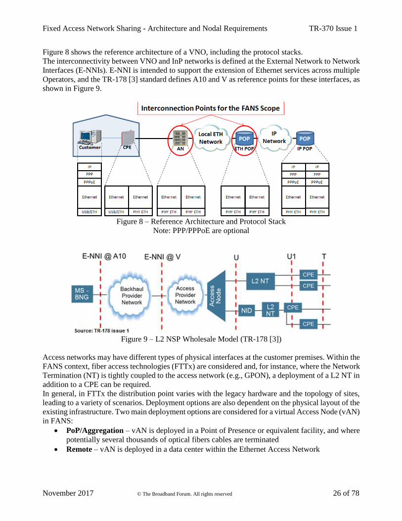
Figure 8 shows the reference architecture of a VNO, including the protocol stacks.
The interconnectivity between VNO and InP networks is defined at the External Network to Network
Interfaces (E-NNIs). E-NNI is intended to support the extension of Ethernet services across multiple
Operators, and the TR-178 [3] standard defines A10 and V as reference points for these interfaces, as
shown in Figure 9.
Figure 8 – Reference Architecture and Protocol Stack
Note: PPP/PPPoE are optional
Figure 9 – L2 NSP Wholesale Model (TR-178 [3])
Access networks may have different types of physical interfaces at the customer premises. Within the
FANS context, fiber access technologies (FTTx) are considered and, for instance, where the Network
Termination (NT) is tightly coupled to the access network (e.g., GPON), a deployment of a L2 NT in
addition to a CPE can be required.
In general, in FTTx the distribution point varies with the legacy hardware and the topology of sites,
leading to a variety of scenarios. Deployment options are also dependent on the physical layout of the
existing infrastructure. Two main deployment options are considered for a virtual Access Node (vAN)
in FANS:
• PoP/Aggregation – vAN is deployed in a Point of Presence or equivalent facility, and where
potentially several thousands of optical fibers cables are terminated
• Remote – vAN is deployed in a data center within the Ethernet Access Network

Fixed Access Network Sharing - Architecture and Nodal Requirements TR-370 Issue 1
November 2017 © The Broadband Forum. All rights reserved 27 of 78
In the remote deployment model, it is important to choose the correct location for the vAN, in terms
of distance from the customer location. The maximum distance depends on the network performance
requirements and SLAs. Typically, a remote option needs an excellent Quality of Service including
low latency.
4.5 QoS / bandwidth allocation models
The FANS architecture enables VNOs to share the same physical network infrastructure. This
includes sharing of the access links between the access node and the customer premises and the
backhaul links within the broadband access network. Therefore the VNOs need to agree the allocation
of capacity on these shared links with the InP.
Broadband internet services are typically offered with a high peak-to-mean bandwidth requirement.
For example, consider a Fiber-to-the-Premises service marketed as 1 Gbit/s downstream and
delivered over GPON infrastructure. Owing to statistical multiplexing, this service may be delivered
with capacity overprovisioned both on the PON and on the backhaul. However, the service would
also need to be able to burst to 1 Gbit/s on demand from the customer to deliver the marketed service.
Within the FANS architecture this service could be delivered in a number of ways:
• Strict bandwidth partitioning
The Centralized Management System must reserve at least 1 Gigabit/s for the VNO on each
network segment traversed by the customer service. This has the benefit that all traffic
management can be performed within the VNO domain (including in stand-alone VNFs).
However, it may result in significant stranded capacity within the access network.
The stranding of capacity may be limited within the backhaul network. Provided that all VNOs
are operating at scale (so the sum of peak average bandwidth per subscriber is in excess of the
peak product rate) provisioning strict capacity backhaul circuits for each VNO may be an
effective way to keep the management of QoS within the VNO’s control.
Strict partitioning can be problematic on the GPON access segment which may need to serve
up to 64 premises with a total downstream capacity of only 2.5Gbit/s. In practice this means
that if service rates exceed 100Mbit/s downstream, VNOs must be offered some form of
statistical access to the total capacity on the PON.
• Flexible bandwidth allocation between VNOs
This is expected to be the more common model of deployment across an access segment (e.g.
PON, FTTx backhaul to a CO). Capacity is allocated to the VNOs depending on both a
Committed Information Rate and Excess Information Rate. These information rates could be
overbooked as part of the Service Level Specification between the InP and VNO. If the shared
link becomes congested, traffic management entities within the InP infrastructure manage the
scheduling of traffic onto the link. The VNOs could mark traffic with classes of service and
drop-precedence to influence this scheduling behavior.
In case of the GPON deployment, the traffic would be scheduled in downstream and upstream
according to the available bandwidth on the GPON. The VNOs would configure the relative

Fixed Access Network Sharing - Architecture and Nodal Requirements TR-370 Issue 1
November 2017 © The Broadband Forum. All rights reserved 28 of 78
bandwidth profiles, classes of service and drop-precedence offered to each of their access services as
part of provisioning via the Centralized Management System.
Fixed Access Network Sharing - Architecture and Nodal Requirements TR-370 Issue 1
November 2017 © The Broadband Forum. All rights reserved 29 of 78
5 Sharing Alternatives
In the following sections two models for resources sharing/slicing are discussed:
• Management System
• Virtual Node
For both solutions, a management system enables multi-vendor support for the FANS scope. The
main difference between these solutions is that the first one can manage existing (legacy) as well as
new network equipment via a centralized management system, while the latter solution, based on the
Virtual Node concept, introduces a high-level abstraction layer, using an NFV Orchestrator (NFVO),
which orchestrates the Virtual Node instances of various operators. The Management System
approach only manages the resources on behalf of VNOs, but the overall resources remain in common
with the physical elements. With Virtual Node approach each physical element is sliced in multiple
partitions and each VNO can access its own virtual resources.
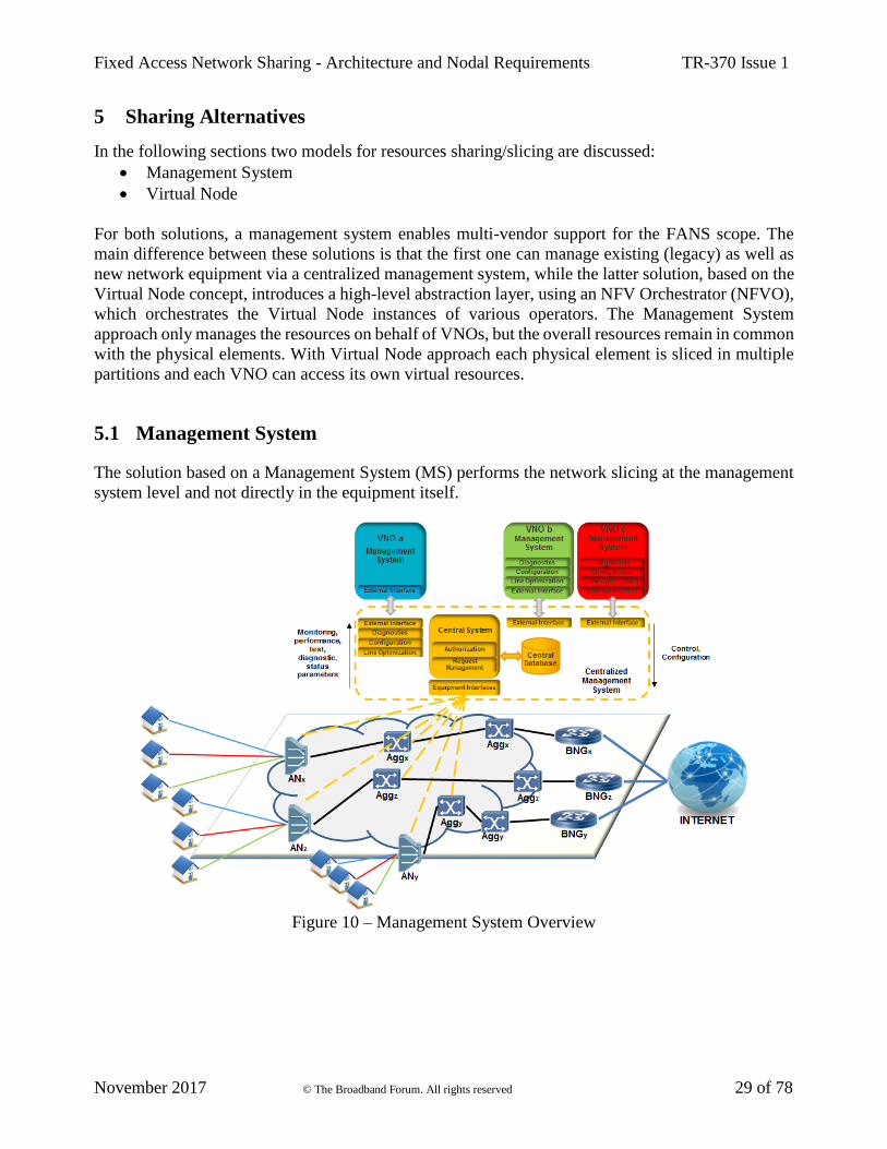
5.1 Management System
The solution based on a Management System (MS) performs the network slicing at the management
system level and not directly in the equipment itself.
Figure 10 – Management System Overview

Fixed Access Network Sharing - Architecture and Nodal Requirements TR-370 Issue 1
November 2017 © The Broadband Forum. All rights reserved 30 of 78
5.1.1 Management System Sharing Architecture
The MS abstracts the central sharing functionality, allowing a modular architecture of network
resource management. The system can work with equipment from multiple vendors and it could be
applied to both legacy and new type types of network equipment. This allows FANS to operate in a
provider-neutral and vendor-neutral manner that is capable of supporting multiple VNOs.
Management system sharing separates the management plane from the data plane, with sharing and
network slicing performed by the management systems that support the management plane. The data
plane can remain unchanged, and data plane functions such as packet forwarding continue to be
performed in the network elements. Aspects of the control plane may also support sharing and
network slicing functions.
In Figure 10, the Northbound Interfaces (NBIs) link the Centralized MS with VNOs management
systems while Southbound Interfaces (SBIs) link it with network equipment and systems. The
“External Interface” to the VNOs should be a standardized interface.
As shown in Figure 11, NBIs can be considered to connect to SBIs through an abstraction layer or an
adaptation layer which converts signals on one side of the interface to equivalent signals on the other
side of the interface. The abstraction or adaptation layer translates FANS transactions between the
Southbound equipment interfaces and the Northbound interfaces to the VNOs. An abstraction layer
hides the details of equipment interfaces to present a simplified interface toward management
systems. An adaptation layer directly translates signals from one format to another format. Adapters
can connect the various equipment interfaces on the SBI to the abstraction or adaptation layer. In this
way, the NBI can provide data and services to VNOs that are independent of details of the actual
equipment deployed.
Figure 11 – Abstraction / adaptation layer concept.
Centralized data sharing could also be thought of as being implemented with the various parties
writing to and reading from a logically centralized database. In this case all necessary management
system functions are still in place, but the interfaces may resemble database read/write actions.
VNO A VNO B
Equipment
Interfaces
Standard sharing
interface
Network sharing system
Abstraction/Adaptation layer
InP

Fixed Access Network Sharing - Architecture and Nodal Requirements TR-370 Issue 1
November 2017 © The Broadband Forum. All rights reserved 31 of 78
The data collection function (DCF) [10] collects data from network elements. There may be a local
DCF, or DCFs, located near the equipment and probably within the InP domain, this can allow low-
delay messaging and good scalability. In this case the data analysis functionality is centralized while
data collection is distributed among the local data collectors. A local DCF separate from the
management system would need a secure interface between itself and the management system; this
interface could be standardized for FANS.
The transactions over the management-system based FANS NBI may either be simplified (coarse-
grained) or parameter-level (fine-grained):
• Simplified NBI transactions can abstract both the data delivered to the VNOs into simpler
summaries, and simplify the control transactions from VNOs into relatively simple “menu”
choices or general indications of preferences such as profile selection. Data can be batched.
Summaries of tests and diagnostics can be provided to the VNOs.
• Parameter-level NBI transactions simply relay requests for data and control to and from
VNOs to the equipment, with little or no simplification or batching. There can be some
combination of both simplified NBI transactions and parameter-level NBI transactions.
5.1.2 Centralized Management System
The Centralized MS covers and performs centralized functions, providing automated data from
network elements (via Equipment Interfaces) to VNOs (via External Interfaces) for a centralized
control and configuration of network elements.
As shown in Figure 10, within the Centralized MS there is an authorization engine and request
management function to enforce policies and avoid potential conflicts or discrepancies in resource
sharing or line settings among VNOs. A Centralized MS can provide for multi-tenancy, perform AAA
functions, perform resource allocation and perform arbitrage between the various parties.
The Centralized MS may run some functions common to multiple operators’ lines such as line
diagnostics and optimization, including multi-line diagnostics and optimization. Moreover,
Centralized MS algorithms can determine some of the finer configuration details. (AAE)
The management system is logically centralized and may be implemented in multiple physical
devices consisting of distributed servers, cloud infrastructure, hosted service, etc.
5.1.3 Resource Management
Resource control allocates available resources such as network capacity, computing capacity and load
balancing, and ensures that available resources are properly allocated.
For InPs, resources are generally network elements and network connections, including network
interfaces, port assignments, VLAN assignments, internal network element bandwidth, network-
facing bandwidth, access bandwidth, network-element internal computational capabilities, the size
and frequency of admissible management messages, and the fiber or metallic facilities themselves as
well as the management systems for these. Moreover, the resources of the Centralized MS itself may
need to be controlled.
Current networks are constrained by limited network resources, and such constraints should be
addressed when different VNOs share the same physical infrastructure. Thus, in the management
system model, the services and resources should be agreed in advance between each VNO and the
Fixed Access Network Sharing - Architecture and Nodal Requirements TR-370 Issue 1
November 2017 © The Broadband Forum. All rights reserved 32 of 78
InP, in order to assure appropriate allocations. This agreement can be indicated by an exchange of
parameters via shared and open interfaces.
VNO A is not allowed to access data about VNO B’s lines and cannot control VNO B’s lines. This
allows VNO A to perform some control actions and line optimization operations on its lines, but it
cannot perform any control on VNO B’s lines. However, via the FANS-based centralized
management system, functions including analysis and diagnostics may access data and perform some
control actions on all the VNOs’ lines.
5.1.4 Management System Sharing Functions
Management system sharing allows a single VNO to choose whether to use their own internal MS to
support all or part of the MS functionality, or to rely on the centralized MS for supporting various
functions. The centralized management system could provide part of the following functionalities to
VNOs for their own slice: which include the following:
• Security, which includes AAA:
o Authentication to verify user credentials
o Authorization to admit requests and limit access
o Accounting to maintain transactional records for billing and other purposes (AAA)
• Virtual Node configuration
• Line optimization for its own lines, without impacting the performances of the lines of other
VNOs
• Testing and gathering of diagnostic data
• Performance monitoring
• Assign bandwidth, VLAN tags and internal AN forwarding cross-connects per virtual port
The following functionalities remain in the hands of InP:
• Network-element configuration
• Line optimization, including multi-line optimization across multiple VNOs
• Fault correlation, particularly for faults that occur on lines or equipment which impact
multiple VNOs
• Maintain inventory, of the physical plant and equipment, as well as the virtual assignment of
resources
• Maintain data needed to access VNOs and equipment
• Support an automated data clearinghouse that allows automated operations
• Provide data to assist VNOs with network planning and to assist in development of innovative
services and differentiated services
• Assign and track port assignments on both the U-interface and V-interface sides of an AN
Fixed Access Network Sharing - Architecture and Nodal Requirements TR-370 Issue 1
November 2017 © The Broadband Forum. All rights reserved 33 of 78
5.2 Virtual Node Sharing Approach
5.2.1 Virtual Access Node
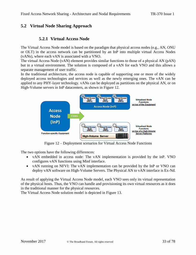
The Virtual Access Node model is based on the paradigm that physical access nodes (e.g., AN, ONU
or OLT) in the access network can be partitioned by an InP into multiple virtual Access Nodes
(vANs), where each vAN is associated with a VNO.
The virtual Access Node (vAN) element provides similar functions to those of a physical AN (pAN)
but in a virtual environment. The solution is composed of a vAN for each VNO and this allows a
separate management of user traffic.
In the traditional architecture, the access node is capable of supporting one or more of the widely
deployed access technologies and services as well as the newly emerging ones. The vAN can be
applied to any PHY-layer technology. vANs can be deployed as partitions on the physical AN, or on
High-Volume servers in InP datacenters, as shown in Figure 12.
Figure 12 – Deployment scenarios for Virtual Access Node Functions
The two options have the following differences:
• vAN embedded in access node: The vAN implementation is provided by the inP. VNO
configures vAN functions using Minf interface.
• vAN running on NFVI: The vAN implementation can be provided by the InP or VNO can
deploy vAN software on High-Volume Servers. The Physical AN to vAN interface is Ex-Nd.
As result of applying the Virtual Access Node model, each VNO sees only its virtual representation
of the physical hosts. Thus, the VNO can handle and provisioning its own virtual resources as it does
in the traditional manner for the physical resources.
The Virtual Access Node solution model is depicted in Figure 13.
Fixed Access Network Sharing - Architecture and Nodal Requirements TR-370 Issue 1
November 2017 © The Broadband Forum. All rights reserved 34 of 78
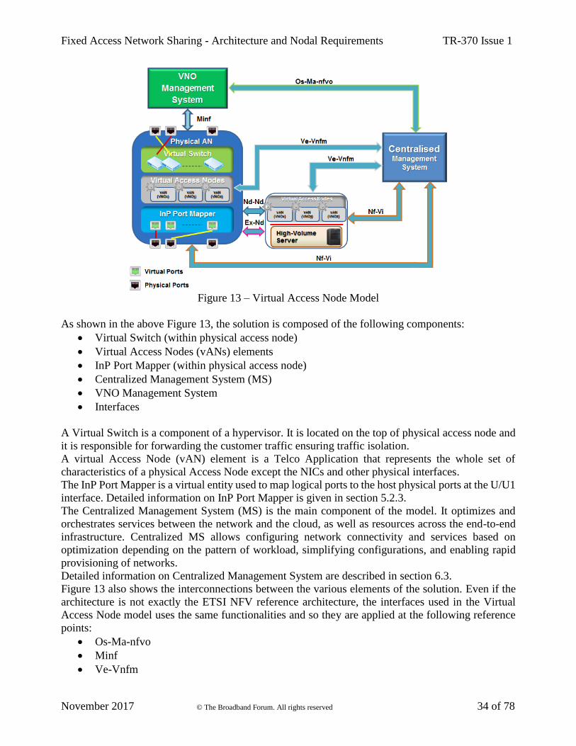
Figure 13 – Virtual Access Node Model
As shown in the above Figure 13, the solution is composed of the following components:
• Virtual Switch (within physical access node)
• Virtual Access Nodes (vANs) elements
• InP Port Mapper (within physical access node)
• Centralized Management System (MS)
• VNO Management System
• Interfaces
A Virtual Switch is a component of a hypervisor. It is located on the top of physical access node and
it is responsible for forwarding the customer traffic ensuring traffic isolation.
A virtual Access Node (vAN) element is a Telco Application that represents the whole set of
characteristics of a physical Access Node except the NICs and other physical interfaces.
The InP Port Mapper is a virtual entity used to map logical ports to the host physical ports at the U/U1
interface. Detailed information on InP Port Mapper is given in section 5.2.3.
The Centralized Management System (MS) is the main component of the model. It optimizes and
orchestrates services between the network and the cloud, as well as resources across the end-to-end
infrastructure. Centralized MS allows configuring network connectivity and services based on
optimization depending on the pattern of workload, simplifying configurations, and enabling rapid
provisioning of networks.
Detailed information on Centralized Management System are described in section 6.3.
Figure 13 also shows the interconnections between the various elements of the solution. Even if the
architecture is not exactly the ETSI NFV reference architecture, the interfaces used in the Virtual
Access Node model uses the same functionalities and so they are applied at the following reference
points:
• Os-Ma-nfvo
• Minf
• Ve-Vnfm
Fixed Access Network Sharing - Architecture and Nodal Requirements TR-370 Issue 1
November 2017 © The Broadband Forum. All rights reserved 35 of 78
• Nf-Vi
• Nd-Nd
• Ex-Nd
These are the main interfaces representing the model. Other interfaces for managing the virtualized
elements are described in section 6.2.
The VNO Management System is used to support various end-to-end telecommunication services. In
general, it can be composed of Operations Support Systems (OSS) and Business Support Systems
(BSS). An OSS covers at least the following five functions:
• Network management systems
• Service delivery
• Service fulfillment (including the network inventory, activation and provisioning)
• Service assurance
• Customer care
A BSS system usually support customer-facing activities, such as:
• Billing
• Order management
• Customer relationship management
• Call center automation
The Os-Ma-nfvo reference point is at the interface between VNO Management Systems and the
Centralized MS. VNO operators access the Management System service portal via a web-based GUI
(which uses this reference point to communicate to the Centralized MS) to perform lifecycle
operations on Virtual Access Nodes and transport circuits (e.g. O-VLANS), such as instantiate,
terminate, query, etc.
Minf reference point is used by VNO Management Systems to configure subscriber services (e.g. C-
VLANs, QoS profiles, OAM) and communicate with the physical Access Node for configuration,
diagnostic and line optimization of the node itself. Note that the allowed set of operations have to be
agreed in advance with the InP.
Ve-Vnfm reference point is used to manage and perform lifecycle operations on vAN elements
passing via the Centralized MS.
Nf-Vi reference point is used to manage the physical resources, networking resources and the
hypervisor-accessed resources (e.g., compute, storage and networking, including InP Port Mapper
and Virtual Switch).
The Nd-Nd reference point supports connectivity between vANs instances over multiple
geographically separated sites.
The Ex-Nd reference point allows vANs to connect to physical Access Nodes.
It is important to note that, for both implementation schemes, the Virtual Switch and InP Port Mapper
functions are resident in the physical access node where the customer lines terminate. This behavior
is depicted in the following Figure 14 and Figure 15.
The Virtual Switch and InP Port Mapper functions implement the slicing system in the Virtual Access
Node model.

Fixed Access Network Sharing - Architecture and Nodal Requirements TR-370 Issue 1
November 2017 © The Broadband Forum. All rights reserved 36 of 78
Figure 14 – vAN inside the Equipment
Figure 15 – vAN in the Cloud
5.2.1.1 An Example Procedure of Virtual Access Node Abstraction
A vAN can be abstracted at the time the VNO asks to lease the infrastructure access network. In this
case, the InP implements the abstraction according to specific requirements from the VNO, including
the virtual resources for the vAN, such as the virtual ports, network functions, etc. After the
deployment, users on the related physical AN who belong to this VNO can access the network through
the already created vAN.

Fixed Access Network Sharing - Architecture and Nodal Requirements TR-370 Issue 1
November 2017 © The Broadband Forum. All rights reserved 37 of 78
Alternatively, it is possible to allocate resources for the Virtual Access Network on-demand.
Figure 16 shows the automated vAN abstraction in the FANS environment.
In this case, the virtual resources of the vAN are not assigned at first. When users of the VNO order
service, the VNO instantiates the service deployment and communicates with the centralized
management system via shared and open interfaces. Some of the configuration parameters related to
the vAN can be generated by the management and control system, which include the description of
the mapping relationship of the physical port ID and the virtual port ID, as well as the virtual resources
and customer line parameters required to support the user’s services. The virtual resources include at
least one of the following:
• Virtual ports (user side ports or network side ports)
• Network functions
• Service functions or service function chain
Figure 16 – vAN Automated Abstraction
When receiving the DHCP packet sent by the user, the physical AN gets a virtual port ID according
to the physical port which the user is connected to, by looking up the mapping relationship of the
Fixed Access Network Sharing - Architecture and Nodal Requirements TR-370 Issue 1
November 2017 © The Broadband Forum. All rights reserved 38 of 78
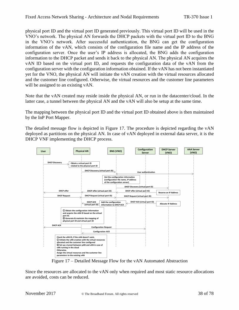
physical port ID and the virtual port ID generated previously. This virtual port ID will be used in the
VNO’s network. The physical AN forwards the DHCP packets with the virtual port ID to the BNG
in the VNO’s network. After successful authentication, the BNG can get the configuration
information of the vAN, which consists of the configuration file name and the IP address of the
configuration server. Once the user’s IP address is allocated, the BNG adds the configuration
information to the DHCP packet and sends it back to the physical AN. The physical AN acquires the
vAN ID based on the virtual port ID, and requests the configuration data of the vAN from the
configuration server with the configuration information obtained. If the vAN has not been instantiated
yet for the VNO, the physical AN will initiate the vAN creation with the virtual resources allocated
and the customer line configured. Otherwise, the virtual resources and the customer line parameters
will be assigned to an existing vAN.
Note that the vAN created may reside inside the physical AN, or run in the datacenter/cloud. In the
latter case, a tunnel between the physical AN and the vAN will also be setup at the same time.
The mapping between the physical port ID and the virtual port ID obtained above is then maintained
by the InP Port Mapper.
The detailed message flow is depicted in Figure 17. The procedure is depicted regarding the vAN
deployed as partitions on the physical AN. In case of vAN deployed in external data server, it is the
DHCP VNF implementing the DHCP process.
Figure 17 – Detailed Message Flow for the vAN Automated Abstraction
Since the resources are allocated to the vAN only when required and most static resource allocations
are avoided, costs can be reduced.
UserDHCP Server
(VNO)Configuration
Server
Check the vAN ID, if the vAN doesn’t exist,① Initiate the vAN creation with the virtual resources allocated and the customer line configured② Set up a tunnel between pAN and vAN in case of vAN running in the cloudOtherwise,Assign the virtual resources and the customer line parameters to the existing vAN
Configuration Request
DHCP Discovery
Configuration ACK
Obtain a virtual port ID related to the physical port ID
Physical AN
DHCP offer (virtual port ID)DHCP offer
DHCP Request
DHCP ACK (virtual port ID)
AAA Server (VNO)
User authentication
DHCP Request (virtual port ID)
DHCP ACK
① Obtain the configuration information and acquire the vAN ID based on the virtual port ID.② Generate & maintain the mapping of physical port ID and virtual port ID
Reserve an IP Address
Allocate IP Address
BNG (VNO)
DHCP Discovery (virtual port ID)
Get the configuration information (configuration file name, IP address of the configuration server)
DHCP Discovery (virtual port ID)
DHCP offer (virtual port ID)
DHCP Request (virtual port ID)
Add the configuration information to DHCP ACK
DHCP ACK (virtual port ID)

Fixed Access Network Sharing - Architecture and Nodal Requirements TR-370 Issue 1
November 2017 © The Broadband Forum. All rights reserved 39 of 78
5.2.2 Virtual Aggregation Node
The Aggregation Node (AggN) aggregates traffic from multiple Access Nodes (AN) in the fixed
aggregation network.
Figure 18 – Network Layers
There may be multiple layers of traffic aggregation. For instance, an Access Node may connect to a
Central office terminal which in turn connects to an Ethernet Aggregation Switch, or multiple levels
of Ethernet aggregation switches can exist.
The “Aggregation” function of the AggN can be implemented in one or more Virtual Network
Functions (similarly to the virtual Access Node) in other physical node(s), or it can be logically
implemented in the Central Office, as shown in Figure 19.
Note that Traffic Engineering (TE) capability, in virtual Aggregation Nodes is based on Operator
VLAN (O-VLAN), MPLS identifiers or VXLAN tunnel as described in section 5.2.6.
Figure 19 – Deployment scenarios for Virtual Aggregation Node Functions
The virtual Aggregation Node (vAggN) element is technology agnostic and provides similar functions
to those of a physical AggN but in a virtual environment. Its control function is provided by a logically
centralized controller in the Centralized MS. In general, some node-related features can be
implemented via a set of Virtual Network Functions (VNFs), such as:
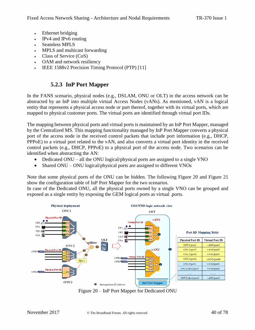
Fixed Access Network Sharing - Architecture and Nodal Requirements TR-370 Issue 1
November 2017 © The Broadband Forum. All rights reserved 40 of 78
• Ethernet bridging
• IPv4 and IPv6 routing
• Seamless MPLS
• MPLS and multicast forwarding
• Class of Service (CoS)
• OAM and network resiliency
• IEEE 1588v2 Precision Timing Protocol (PTP) [11]
5.2.3 InP Port Mapper
In the FANS scenario, physical nodes (e.g., DSLAM, ONU or OLT) in the access network can be
abstracted by an InP into multiple virtual Access Nodes (vANs). As mentioned, vAN is a logical
entity that represents a physical access node or part thereof, together with its virtual ports, which are
mapped to physical customer ports. The virtual ports are identified through virtual port IDs.
The mapping between physical ports and virtual ports is maintained by an InP Port Mapper, managed
by the Centralized MS. This mapping functionality managed by InP Port Mapper converts a physical
port of the access node in the received control packets that include port information (e.g., DHCP,
PPPoE) to a virtual port related to the vAN, and also converts a virtual port identity in the received
control packets (e.g., DHCP, PPPoE) to a physical port of the access node. Two scenarios can be
identified when abstracting the AN:
• Dedicated ONU – all the ONU logical/physical ports are assigned to a single VNO
• Shared ONU – ONU logical/physical ports are assigned to different VNOs
Note that some physical ports of the ONU can be hidden. The following Figure 20 and Figure 21
show the configuration table of InP Port Mapper for the two scenarios.
In case of the Dedicated ONU, all the physical ports owned by a single VNO can be grouped and
exposed as a single entity by exposing the GEM logical ports as virtual .ports.
Figure 20 – InP Port Mapper for Dedicated ONU

Fixed Access Network Sharing - Architecture and Nodal Requirements TR-370 Issue 1
November 2017 © The Broadband Forum. All rights reserved 41 of 78
Figure 21 – InP Port Mapper for Shared ONU
For both cases, the vAN has visibility of those virtual ports assigned to it.
In essence, the InP Port Mapper is a powerful virtual switch and as such, provides network-level data
routing and switching functionality between virtual and physical ports. The case of customer
migrations between different VNOs terminating on the same physical access node is shown in Figure
22.
Figure 22 – Customer Migration in FANS
The customer is a subscriber to services (represented by the yellow line) of VNOx, but needs to
migrate these services to VNOy. Where the migration leaves the customer on the same physical AN,

Fixed Access Network Sharing - Architecture and Nodal Requirements TR-370 Issue 1
November 2017 © The Broadband Forum. All rights reserved 42 of 78
there is no need for manual intervention on that AN, just a simple change in the mapping between
virtual and physical ports. The physical port which the customer is connected to remains the same
after the migration.
Note that the InP Port Mapper is resident in the physical access node although the vAN is deployed
in the InP’s datacenter.
Virtual Port state information is a convenient way of providing O&M status to the VNO. Providing a
set of retrievable states, allows the VNO to manage virtual ports with regard to deployment, migration
and trouble-shooting.
The InP Port Mapper establishes the relationship between physical ports of an Access Node and the
virtual ports of a vAN. Virtual ports represent a group of physical InP ports to which customers are
connected, and this mapping is retrievable by the Centralized MS. The Centralized MS is in charge
of virtual port state management when the VNO leases resources from InPs.
The VNO monitors and administrates virtual port state for most operations. When trouble-shooting
network problems, the status message records and correlation between vAN virtual port and InP
physical port may help to locate the problem.
The Port State of a virtual port is retrievable and settable by the Centralized MS. The following states
represent the physical link connection of the port, port operational and administrative state exists
when several states are valid simultaneously.
Port State:
• LINKUP –physical port has no alarm/defect, which implies the link connection is good.
• LINKDOWN –physical port has alarm/defect, which implies the link connection has failed.
• PORTUP – port is administratively up. This is the default state when a port is added, and it
transits to the LINKUP/LINKDOWN/PORTDOWN state after system power-up.
• PORTDOWN – follows the LINKUP/LINKDOWN/PORTUP when port is administratively
down.
The Port Status of a virtual port is transient and reported as event message which is retrievable on
Centralized MS.
Port Actions:
• ADD – Add a virtual port to a given vAN.
• DELETE – Delete a virtual port from a given vAN.
• MODIFY – Bring virtual port administratively up or down.
The following Figure 23 demonstrates the virtual port state machine and associated status.
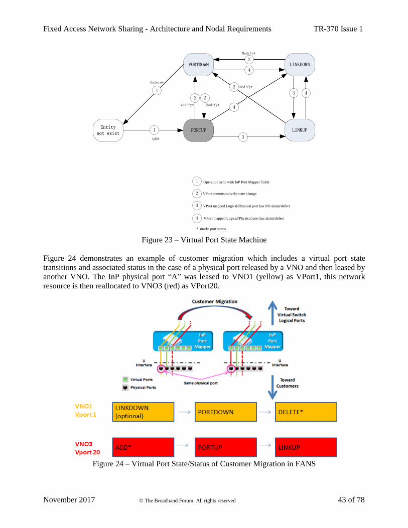
Fixed Access Network Sharing - Architecture and Nodal Requirements TR-370 Issue 1
November 2017 © The Broadband Forum. All rights reserved 43 of 78
PORTDOWN
PORTUPEntity
not existLINKUP
LINKDOWN
3
3 4
2
4
2
2
Modify*
Modify*
Modify*
1
1
Add*
Delete*
* marks port status
VPort mapped Logical/Physical port has NO alarm/defect 3
4
VPort administratively state change 2
Operation sync with InP Port Mapper Table1
VPort mapped Logical/Physical port has alarm/defect
4
2
Modify*
Figure 23 – Virtual Port State Machine
Figure 24 demonstrates an example of customer migration which includes a virtual port state
transitions and associated status in the case of a physical port released by a VNO and then leased by
another VNO. The InP physical port “A” was leased to VNO1 (yellow) as VPort1, this network
resource is then reallocated to VNO3 (red) as VPort20.
Figure 24 – Virtual Port State/Status of Customer Migration in FANS

Fixed Access Network Sharing - Architecture and Nodal Requirements TR-370 Issue 1
November 2017 © The Broadband Forum. All rights reserved 44 of 78
During the customer migration, VNO1 needs take down virtual port1 in VNO1’s management system,
and release the virtual port by deleting it from VNO1. VNO3 maps physical port “A” to VNO3’s
management system as VPort20, takes the port up administratively, and then VPort20 appears as
LINKUP or LINKDOWN depending on the condition of link connection. Note that these migrations
should synchronize with InP Port Mapper table operation, and vice versa.
Figure 25 shows another case where a given VNO detects MAC spoofing and prompt action is taken
to block this traffic by putting the virtual port VPort1 into Linkdown State.
Figure 25 – VNO Block Traffic when MAC Spoofing is Identified
In this case, the VNO detects that data from VPort1 and VPort2 has the same MAC address.
As per the subscriber and VNO contract, only VPort1 is legitimately associated with a given MAC.
The VNO blocks the data from VPort2 immediately and modifies the VNO MAC learning process
accordingly so the port in not re-enabled.
5.2.4 Access Network Function as a Service
A vAN and its virtual ports can be deployed and maintained by an InP who implements the access
network abstraction and slicing. Physical nodes in the access network can be combined or segregated
to form different vANs. As part of ensuring network isolation, VNOs can control and manage their
own vAN instances and virtual port IDs.
A vAN can be deployed as a single, complete AN virtual function or it can have a subset of access
network functions (in control plane or data plane) to support different services as required by a given
VNO. These functions are already defined in TR-101 [2], TR-178 [3], TR-156 [4], TR-167 [8] and
TR-221 [9]. The granularity of the network function is flexible so that several functions can be
combined as a service, as illustrated in Figure 26.
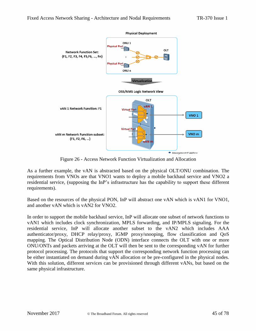
Fixed Access Network Sharing - Architecture and Nodal Requirements TR-370 Issue 1
November 2017 © The Broadband Forum. All rights reserved 45 of 78
Figure 26 - Access Network Function Virtualization and Allocation
As a further example, the vAN is abstracted based on the physical OLT/ONU combination. The
requirements from VNOs are that VNO1 wants to deploy a mobile backhaul service and VNO2 a
residential service, (supposing the InP’s infrastructure has the capability to support these different
requirements).
Based on the resources of the physical PON, InP will abstract one vAN which is vAN1 for VNO1,
and another vAN which is vAN2 for VNO2.
In order to support the mobile backhaul service, InP will allocate one subset of network functions to
vAN1 which includes clock synchronization, MPLS forwarding, and IP/MPLS signaling. For the
residential service, InP will allocate another subset to the vAN2 which includes AAA
authenticator/proxy, DHCP relay/proxy, IGMP proxy/snooping, flow classification and QoS
mapping. The Optical Distribution Node (ODN) interface connects the OLT with one or more
ONU/ONTs and packets arriving at the OLT will then be sent to the corresponding vAN for further
protocol processing. The protocols that support the corresponding network function processing can
be either instantiated on demand during vAN allocation or be pre-configured in the physical nodes.
With this solution, different services can be provisioned through different vANs, but based on the
same physical infrastructure.

Fixed Access Network Sharing - Architecture and Nodal Requirements TR-370 Issue 1
November 2017 © The Broadband Forum. All rights reserved 46 of 78
5.2.5 Relationship to ETSI NFV Architecture
Figure 27 shows how the ETSI NFV architecture can be leveraged to enable FANS for both existing
and new deployments.
Figure 27 – Applicability of ETSI NFV architecture for Fixed Access Network Sharing
The vRG and vBNG are not required as part of Fixed Access Network Sharing architecture. However
in the case where the RG and BNG are virtualized, the vRG and vBNG functions may reside in the
same NFVI which also hosts vAN functions, or in an NFVI in the VNO domain.
As can be seen, several of the concepts in Figure 27 are aligned with the Virtual Access Node Model,
outline in Figure 13/Section 5.2.1.
The Access Node is shown to consist of two functions:
• The Access Function provides physical layer access (e.g. terminating the G.fast interface)
and framing, offering an Ethernet layer 2 service towards the Forwarding Function
• The Forwarding Function provides connectivity across the aggregation network, via the
NFVI-GW into the NFVI where some Virtual Access Node functions may be hosted. These
tunnels are instantiated per Virtual Network Operator (VNO) and carry the traffic of one or
more access lines (e.g. one or more UNIs on a GPON ONT) towards the vAN in the NFVI.
The NFVI maintains a set of VNFs that implement the service model for each of the VNOs. These
VNFs may include the existing vRG (NERG), but may also include other VNFs that implement some
of the functions that traditionally reside in the Access Node and/or the Broadband Network Gateway.
In general, one or more subscriber management related features can be moved into the NFVI and
implemented via a set of VNFs.
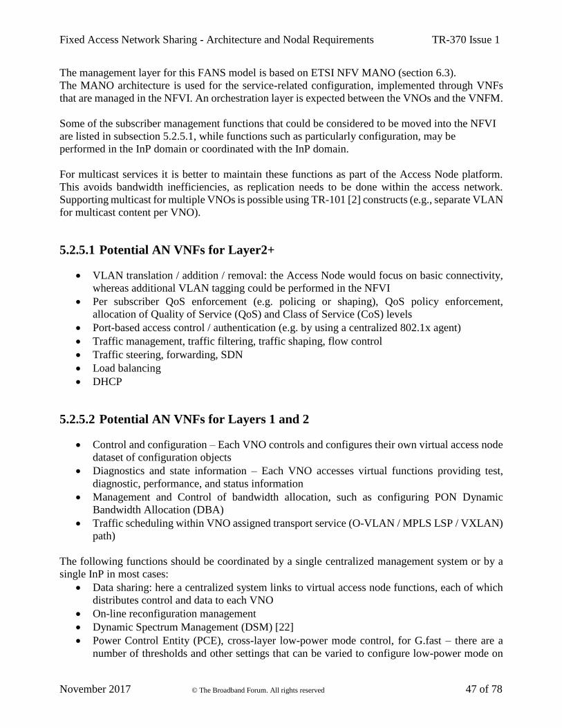
Fixed Access Network Sharing - Architecture and Nodal Requirements TR-370 Issue 1
November 2017 © The Broadband Forum. All rights reserved 47 of 78
The management layer for this FANS model is based on ETSI NFV MANO (section 6.3).
The MANO architecture is used for the service-related configuration, implemented through VNFs
that are managed in the NFVI. An orchestration layer is expected between the VNOs and the VNFM.
Some of the subscriber management functions that could be considered to be moved into the NFVI
are listed in subsection 5.2.5.1, while functions such as particularly configuration, may be
performed in the InP domain or coordinated with the InP domain.
For multicast services it is better to maintain these functions as part of the Access Node platform.
This avoids bandwidth inefficiencies, as replication needs to be done within the access network.
Supporting multicast for multiple VNOs is possible using TR-101 [2] constructs (e.g., separate VLAN
for multicast content per VNO).
5.2.5.1 Potential AN VNFs for Layer2+
• VLAN translation / addition / removal: the Access Node would focus on basic connectivity,
whereas additional VLAN tagging could be performed in the NFVI
• Per subscriber QoS enforcement (e.g. policing or shaping), QoS policy enforcement,
allocation of Quality of Service (QoS) and Class of Service (CoS) levels
• Port-based access control / authentication (e.g. by using a centralized 802.1x agent)
• Traffic management, traffic filtering, traffic shaping, flow control
• Traffic steering, forwarding, SDN
• Load balancing
• DHCP
5.2.5.2 Potential AN VNFs for Layers 1 and 2
• Control and configuration – Each VNO controls and configures their own virtual access node
dataset of configuration objects
• Diagnostics and state information – Each VNO accesses virtual functions providing test,
diagnostic, performance, and status information
• Management and Control of bandwidth allocation, such as configuring PON Dynamic
Bandwidth Allocation (DBA)
• Traffic scheduling within VNO assigned transport service (O-VLAN / MPLS LSP / VXLAN)
path)
The following functions should be coordinated by a single centralized management system or by a
single InP in most cases:
• Data sharing: here a centralized system links to virtual access node functions, each of which
distributes control and data to each VNO
• On-line reconfiguration management
• Dynamic Spectrum Management (DSM) [22]
• Power Control Entity (PCE), cross-layer low-power mode control, for G.fast – there are a
number of thresholds and other settings that can be varied to configure low-power mode on

Fixed Access Network Sharing - Architecture and Nodal Requirements TR-370 Issue 1
November 2017 © The Broadband Forum. All rights reserved 48 of 78
individual transceivers and these settings and primitives can be determined in a virtualized
power control entity and communicated to the transceivers
• Vectoring control and management – Virtualized functions can control part of the vectoring
configuration, and could even calculate vectoring coefficients
5.2.6 VNO Traffic Encapsulation Models
VLANs play an integral role in the design and implementation of the FANS architecture. In the shared
scenario, Internet services can have very different requirements and thus it is difficult to accommodate
all these services (among different customers) in a single network.
To cope with this, a possible approach is to set up isolated networks for the different customers by
using VLAN, MPLS or a VXLAN tunnel approaches. These tunneling approaches are implemented
by the physical access and aggregation nodes. The tunnels are not visible to the VNO or any VNFs
implementing the virtual access node. Selection of the tunneling mechanism will depend on the
hardware capabilities of the physical access node.
5.2.6.1 VLAN Tunnel
In the FANS context, the VLAN approach introduces “Operator VLAN (O-VLAN) Tag” tagging and
forwarding rules. O-VLAN tag information is agreed between the VNO and InP and is added to the
Ethernet frame at the interconnection point (at the A10 reference point). The following Figure 28
depicts the end-to-end VLAN scheme used in FANS.
In a network with multiple VLANs, it is important to correctly configure the VLANs which the
network elements use to send management traffic.
Thus, it is necessary to extend the O-VLAN tag up to the vAN which represents the access point
which terminates the customers’ lines, in order to handle the configuration of the same network
element.
As shown in Figure 28, the C-VLAN tag information is transmitted through the network. In the
downstream direction, the operator VLAN (O-VLAN) information is added to the Ethernet frame at
the switch adjacent to the A10 reference point. These information tags remain up to the pAN.
Conversely, in the upstream direction, the S-VLAN and O-VLAN tag information is added to the C-
VLAN tag within the Ethernet frame at the pAN. It is important to note that O-VLAN information is
discarded at the switch adjacent to the A10 reference, while the S-VLAN information continues to be
forwarded in the VNO’s network.
Some operators use Q-in-Q (IEEE 802.1ad [6]) tunneling (which extends IEEE 802.1Q [5]) and
VLAN translation to create L2 Ethernet connections. Q-in-Q increases the VLAN number to 16
million (4094 * 4094) which results in the Ethernet frame size being increased (from 1522 to 1526
bytes).
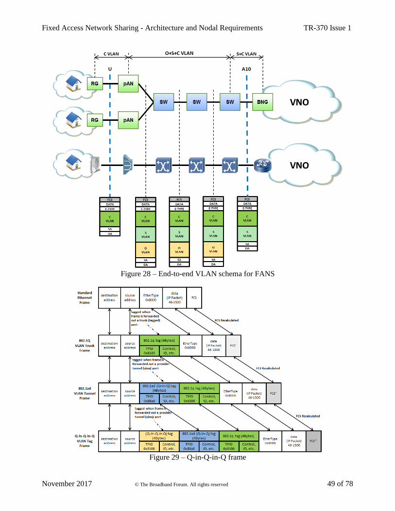
Fixed Access Network Sharing - Architecture and Nodal Requirements TR-370 Issue 1
November 2017 © The Broadband Forum. All rights reserved 49 of 78
Figure 28 – End-to-end VLAN schema for FANS
Figure 29 – Q-in-Q-in-Q frame

Fixed Access Network Sharing - Architecture and Nodal Requirements TR-370 Issue 1
November 2017 © The Broadband Forum. All rights reserved 50 of 78
The second tag is inserted in front of the first tag i.e. closer to the Ethernet header. Any third or
subsequent tag imposition will be inserted in front, i.e. closest to the Ethernet header. The frame's
original EtherType is always located above all the tags, next to the payload, as shown in the following
Figure 29.
The Q-in-Q-in-Q VLAN Tag is shown in Figure 30.
Figure 30 – Q-in-Q-in-Q VLAN frame detail
5.2.6.2 MPLS Tunnel
Another possible technique that could be used in the FANS scenario to manage the operators’ data
flows, is a label-based switching technique, such as Multi-Protocol Label Switching (MPLS), as
depicted in the following Figure 31.
The main difference between the MPLS scheme and the VLAN model is the presence of a MPLS
tunnel (defined using LSP labels) which contains the C-VLAN tag and S-VLAN tag information.
As shown in Figure 31, the C-VLAN tag information is transmitted through the network. In the
downstream direction, the MPLS LSP information is added to the Ethernet frame at the PE router
adjacent to the A10 reference point. These information tags remain up to the pAN, that must act as
PE router. Conversely, in the upstream direction, the S-VLAN information is added to the C-VLAN
tag within the Ethernet frame at the vAN, while the MPLS LSP information is added to the Ethernet
frame at the pAN. It is important to note that MPLS tag information is discarded at the switch adjacent
to the A10 reference point, while the S-VLAN information continues to be forwarded in the VNO’s
network. However, despite the flexible and scalable network architecture brought by about by MPLS,
in a purely L2 evolution context, it might be useful to consider the use of the O-VLAN scheme rather
than the L2.5 MPLS extension to the access network. Another motivation is that current access nodes
may not support MPLS, but adding MPLS capability can increase the complexity and cost of the
node.
5.2.6.3 VXLAN Tunnel
In addition to the O-VLAN and MPLS schemes, Virtual eXtensible Local Area Network (VXLAN)
can also be deployed in the FANS scenario to separate the operator’s traffic. The end-to-end VXLAN
scheme is depicted in Figure 32.
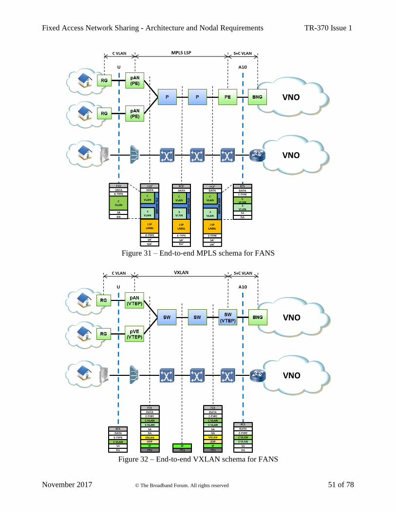
Fixed Access Network Sharing - Architecture and Nodal Requirements TR-370 Issue 1
November 2017 © The Broadband Forum. All rights reserved 51 of 78
Figure 31 – End-to-end MPLS schema for FANS
Figure 32 – End-to-end VXLAN schema for FANS
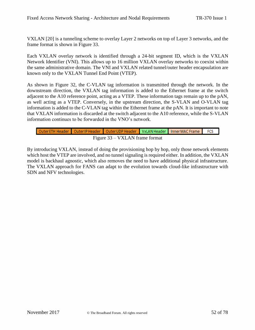
Fixed Access Network Sharing - Architecture and Nodal Requirements TR-370 Issue 1
November 2017 © The Broadband Forum. All rights reserved 52 of 78
VXLAN [20] is a tunneling scheme to overlay Layer 2 networks on top of Layer 3 networks, and the
frame format is shown in Figure 33.
Each VXLAN overlay network is identified through a 24-bit segment ID, which is the VXLAN
Network Identifier (VNI). This allows up to 16 million VXLAN overlay networks to coexist within
the same administrative domain. The VNI and VXLAN related tunnel/outer header encapsulation are
known only to the VXLAN Tunnel End Point (VTEP).
As shown in Figure 32, the C-VLAN tag information is transmitted through the network. In the
downstream direction, the VXLAN tag information is added to the Ethernet frame at the switch
adjacent to the A10 reference point, acting as a VTEP. These information tags remain up to the pAN,
as well acting as a VTEP. Conversely, in the upstream direction, the S-VLAN and O-VLAN tag
information is added to the C-VLAN tag within the Ethernet frame at the pAN. It is important to note
that VXLAN information is discarded at the switch adjacent to the A10 reference, while the S-VLAN
information continues to be forwarded in the VNO’s network.
Figure 33 – VXLAN frame format
By introducing VXLAN, instead of doing the provisioning hop by hop, only those network elements
which host the VTEP are involved, and no tunnel signaling is required either. In addition, the VXLAN
model is backhaul agnostic, which also removes the need to have additional physical infrastructure.
The VXLAN approach for FANS can adapt to the evolution towards cloud-like infrastructure with
SDN and NFV technologies.
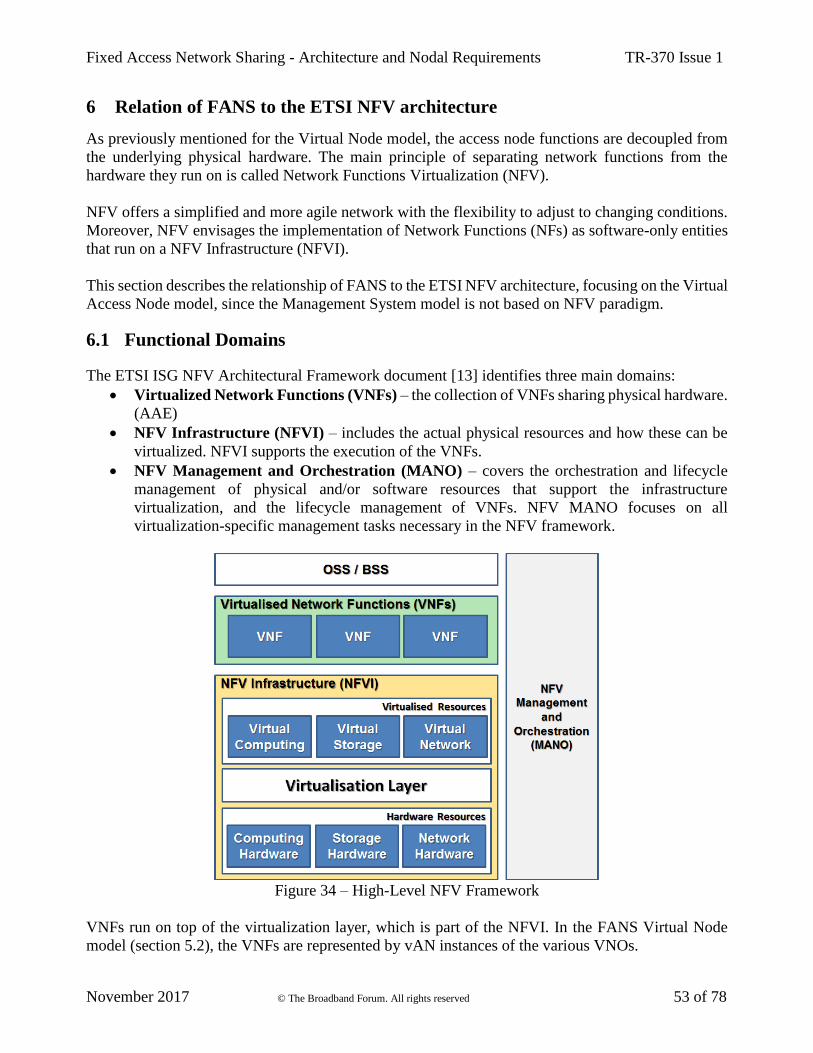
Fixed Access Network Sharing - Architecture and Nodal Requirements TR-370 Issue 1
November 2017 © The Broadband Forum. All rights reserved 53 of 78
6 Relation of FANS to the ETSI NFV architecture
As previously mentioned for the Virtual Node model, the access node functions are decoupled from
the underlying physical hardware. The main principle of separating network functions from the
hardware they run on is called Network Functions Virtualization (NFV).
NFV offers a simplified and more agile network with the flexibility to adjust to changing conditions.
Moreover, NFV envisages the implementation of Network Functions (NFs) as software-only entities
that run on a NFV Infrastructure (NFVI).
This section describes the relationship of FANS to the ETSI NFV architecture, focusing on the Virtual
Access Node model, since the Management System model is not based on NFV paradigm.
6.1 Functional Domains
The ETSI ISG NFV Architectural Framework document [13] identifies three main domains:
• Virtualized Network Functions (VNFs) – the collection of VNFs sharing physical hardware.
(AAE)
• NFV Infrastructure (NFVI) – includes the actual physical resources and how these can be
virtualized. NFVI supports the execution of the VNFs.
• NFV Management and Orchestration (MANO) – covers the orchestration and lifecycle
management of physical and/or software resources that support the infrastructure
virtualization, and the lifecycle management of VNFs. NFV MANO focuses on all
virtualization-specific management tasks necessary in the NFV framework.
Figure 34 – High-Level NFV Framework
VNFs run on top of the virtualization layer, which is part of the NFVI. In the FANS Virtual Node
model (section 5.2), the VNFs are represented by vAN instances of the various VNOs.
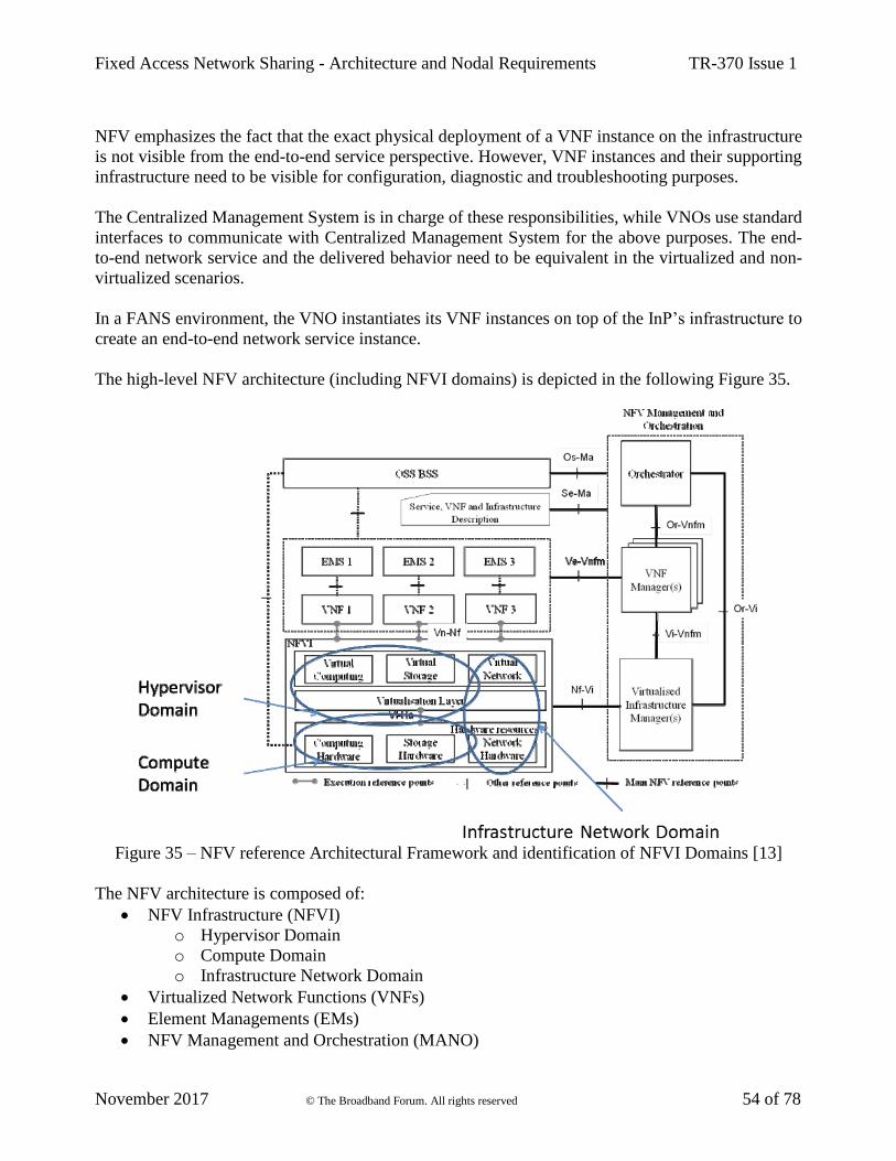
Fixed Access Network Sharing - Architecture and Nodal Requirements TR-370 Issue 1
November 2017 © The Broadband Forum. All rights reserved 54 of 78
NFV emphasizes the fact that the exact physical deployment of a VNF instance on the infrastructure
is not visible from the end-to-end service perspective. However, VNF instances and their supporting
infrastructure need to be visible for configuration, diagnostic and troubleshooting purposes.
The Centralized Management System is in charge of these responsibilities, while VNOs use standard
interfaces to communicate with Centralized Management System for the above purposes. The end-
to-end network service and the delivered behavior need to be equivalent in the virtualized and non-
virtualized scenarios.
In a FANS environment, the VNO instantiates its VNF instances on top of the InP’s infrastructure to
create an end-to-end network service instance.
The high-level NFV architecture (including NFVI domains) is depicted in the following Figure 35.
Figure 35 – NFV reference Architectural Framework and identification of NFVI Domains [13]
The NFV architecture is composed of:
• NFV Infrastructure (NFVI)
o Hypervisor Domain
o Compute Domain
o Infrastructure Network Domain
• Virtualized Network Functions (VNFs)
• Element Managements (EMs)
• NFV Management and Orchestration (MANO)

Fixed Access Network Sharing - Architecture and Nodal Requirements TR-370 Issue 1
November 2017 © The Broadband Forum. All rights reserved 55 of 78
• Virtualized Infrastructure Manager(s) (VIMs)
• VNF Manager(s) (VNFMs)
• Service, VNF and Infrastructure Description
• NFV Orchestrator (NFVO)
• Operations & Business Support Systems (OSS/BSS)
It is important to note that a network operator who uses a traditional network architecture, still needs
at least one management system, for instance an EMS (or an NMS), supported by an OSS system.
In the NFV architecture, multiple managers (e.g., VIM Manager, VNF Manager Orchestrator and also
the traditional EMS and OSS/BSS) are needed. Moreover, EM, VNFM and any other entity identified
by the NFV architecture framework, may be virtualized or not.
The scope of this section is to describe the functional domains of the ETSI NFV architecture [13], as
well as the main reference points between these blocks and how the Virtual Access Node model
(Figure 36) is related to this architecture.
Figure 36 – Virtual Access Node Model
6.1.1 NFV Infrastructure (NFVI) Domain
The NFV Infrastructure (NFVI) is composed of hardware and software components that build up the
environment in which VNFs are deployed, managed and executed. The NFVI may also include
partially virtualized Network Functions (NFs), in which a certain part of the functionality is
virtualized while other parts remain in hardware (PNF) for performance reasons, protect investment
or ease of migration.
The execution environment for VNFs is provided by the NFVI deployed in various NFVI Point of
Presence (NFVI-PoPs).
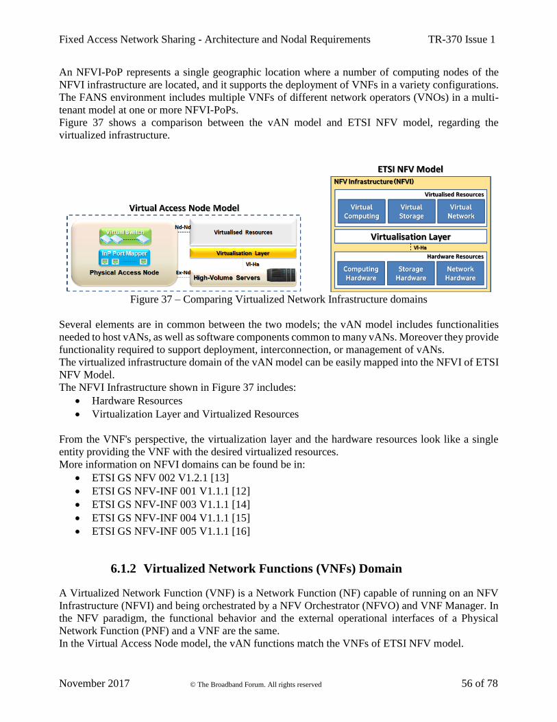
Fixed Access Network Sharing - Architecture and Nodal Requirements TR-370 Issue 1
November 2017 © The Broadband Forum. All rights reserved 56 of 78
An NFVI-PoP represents a single geographic location where a number of computing nodes of the
NFVI infrastructure are located, and it supports the deployment of VNFs in a variety configurations.
The FANS environment includes multiple VNFs of different network operators (VNOs) in a multi-
tenant model at one or more NFVI-PoPs.
Figure 37 shows a comparison between the vAN model and ETSI NFV model, regarding the
virtualized infrastructure.
Figure 37 – Comparing Virtualized Network Infrastructure domains
Several elements are in common between the two models; the vAN model includes functionalities
needed to host vANs, as well as software components common to many vANs. Moreover they provide
functionality required to support deployment, interconnection, or management of vANs.
The virtualized infrastructure domain of the vAN model can be easily mapped into the NFVI of ETSI
NFV Model.
The NFVI Infrastructure shown in Figure 37 includes:
• Hardware Resources
• Virtualization Layer and Virtualized Resources
From the VNF's perspective, the virtualization layer and the hardware resources look like a single
entity providing the VNF with the desired virtualized resources.
More information on NFVI domains can be found be in:
• ETSI GS NFV 002 V1.2.1 [13]
• ETSI GS NFV-INF 001 V1.1.1 [12]
• ETSI GS NFV-INF 003 V1.1.1 [14]
• ETSI GS NFV-INF 004 V1.1.1 [15]
• ETSI GS NFV-INF 005 V1.1.1 [16]
6.1.2 Virtualized Network Functions (VNFs) Domain
A Virtualized Network Function (VNF) is a Network Function (NF) capable of running on an NFV
Infrastructure (NFVI) and being orchestrated by a NFV Orchestrator (NFVO) and VNF Manager. In
the NFV paradigm, the functional behavior and the external operational interfaces of a Physical
Network Function (PNF) and a VNF are the same.
In the Virtual Access Node model, the vAN functions match the VNFs of ETSI NFV model.
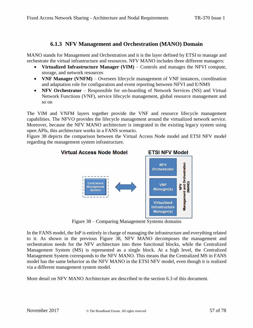
Fixed Access Network Sharing - Architecture and Nodal Requirements TR-370 Issue 1
November 2017 © The Broadband Forum. All rights reserved 57 of 78
6.1.3 NFV Management and Orchestration (MANO) Domain
MANO stands for Management and Orchestration and it is the layer defined by ETSI to manage and
orchestrate the virtual infrastructure and resources. NFV MANO includes three different managers:
• Virtualized Infrastructure Manager (VIM) – Controls and manages the NFVI compute,
storage, and network resources
• VNF Manager (VNFM) – Oversees lifecycle management of VNF instances, coordination
and adaptation role for configuration and event reporting between NFVI and E/NMS
• NFV Orchestrator – Responsible for on-boarding of Network Services (NS) and Virtual
Network Functions (VNF), service lifecycle management, global resource management and
so on
The VIM and VNFM layers together provide the VNF and resource lifecycle management
capabilities. The NFVO provides the lifecycle management around the virtualized network service.
Moreover, because the NFV MANO architecture is integrated in the existing legacy system using
open APIs, this architecture works in a FANS scenario.
Figure 38 depicts the comparison between the Virtual Access Node model and ETSI NFV model
regarding the management system infrastructure.
Figure 38 – Comparing Management Systems domains
In the FANS model, the InP is entirely in charge of managing the infrastructure and everything related
to it. As shown in the previous Figure 38, NFV MANO decomposes the management and
orchestration needs for the NFV architecture into three functional blocks, while the Centralized
Management System (MS) is represented as a single block. At a high level, the Centralized
Management System corresponds to the NFV MANO. This means that the Centralized MS in FANS
model has the same behavior as the NFV MANO in the ETSI NFV model, even though it is realized
via a different management system model.
More detail on NFV MANO Architecture are described in the section 6.3 of this document.

Fixed Access Network Sharing - Architecture and Nodal Requirements TR-370 Issue 1
November 2017 © The Broadband Forum. All rights reserved 58 of 78
6.2 Interfaces & Reference Points
An interface is a point of interaction between two entities that can be software services, hardware
services and resources, while a reference point is an architectural concept that defines and exposes an
external view of a function block.
The following Figure 39 depicts a reference point architecture, showing only the NFVI Network
Domain and aligning these reference points with the NFV E2E Architecture [16].
Figure 39 – Network Domain Reference Point Architecture [16]
Some of the reference points described in Figure 35 and Figure 39, have a 1:1 relation with those in
Virtual Access Node model (Figure 36).
This section describes the main reference points between the functional blocks described in the
previous section 6.1 and their relation with the FANS model. For the entire set of reference points,
refer to the ETSI NFV documentation.
6.2.1 NFVI - Virtualized Infrastructure Manager (Nf-Vi)
In the vAN model, the Nf-Vi reference point is applied between the InP and the access infrastructure
(physical access nodes, including virtual infrastructure, and servers in datacenters) as described in
[17].
6.2.2 VNF/EM - VNF Manager (Ve-Vnfm)
The vAN model uses the Ve-Vnfm reference point to support communication between the virtual
functions (vAN instances) and the Centralized Management System as described in [17].
Fixed Access Network Sharing - Architecture and Nodal Requirements TR-370 Issue 1
November 2017 © The Broadband Forum. All rights reserved 59 of 78
6.2.3 OSS/BSS - NFV Management and Orchestration (Os-Ma)
Similar to the Os-Ma in [17] in the vAN model, the Os-Ma-nfvo reference point supports information
transfer between VNO Management System and Centralized Management System.
6.2.4 OSS/BSS – Physical Infrastructure
A reference point is needed to support communication between VNO MS and the pAN.
In this scenario, NMS/EMS systems should be aware of virtualization and collaborate with the
Centralized MS (via Os-Ma-nfvo reference point) to perform functions that require exchange of
information on resources lifecycle.
Note that this reference point is represented in the NFV reference Architectural Framework [13], but
not yet specified, as shown in Figure 35. However, in BBF TR-359 [7] the “Minf” reference point is
defined between OS/EM/WIM and the network elements within the physical infrastructure. This
reference point has similar characteristics to the one needed in FANS architecture.
6.2.5 Virtualization Layer - Hardware Resources (Vl-Ha)
The Virtualization Layer is a key component in the ETSI NFV architectural framework. This layer
abstracts and logically partitions physical hardware resources and provides anchors between the VNF
and the underlying virtualized infrastructure.
The Vl-Ha described in [12] is an internal reference point that interfaces the Virtualization Layer to
hardware resources to create an execution environment for VNFs, and collect hardware resource state
information for managing the VNFs independently from any hardware platform. This allows the
decoupling of software from hardware.
6.2.6 VNF - NFV Infrastructure (Vn-Nf)
The Vn-Nf reference point described in [13] represents the execution environment used by VNFs to
be executed on NFVI in ETSI NFV framework. It does not assume any specific control protocol, but
in the FANS scenario, the Vn-Nf reference point uses a set of APIs to get access to the NFVI.
6.2.7 Infrastructure Network Domain - Existing Network (Ex-Nd)
The provision of connectivity between a vAN and a pAN in existing networks, requires the use of the
Ex-Nd. More detail on Ex-Nd interface can be found be in [16].
6.2.8 NFV Infrastructure (Nd-Nd)
The Nd-Nd interface consists of protocols that are exposed between the NFVI-PoPs to provide
connectivity between VNFs located in different NFVI-PoPs, regardless of the connectivity service
provided. More detail on Nd-Nd interface can be found be in [16].

Fixed Access Network Sharing - Architecture and Nodal Requirements TR-370 Issue 1
November 2017 © The Broadband Forum. All rights reserved 60 of 78
6.3 NFV MANO
The vAN model does not impose any constraint (in terms of internal module numbers) on the
Centralized Management System. The Centralized Management System could be a single point of
management or it could have multiple internal management modules. In any case, it is important to
note that Centralized Management System and NFV MANO have the same behavior toward external
systems or infrastructures.
Figure 40 – Virtual Access Node model: Centralized Management System roles
In the FANS architecture, the Centralized Management System is the main component of the model.
It is in charge of the orchestration and management of both physical infrastructure and software
resources, as well as governance of those vAN instances that share resources of the FANS
infrastructure. Moreover, it is responsible for the lifecycle management of the vANs, including their
creation, provisioning, and monitoring.
Finally, an internal data repository provides information for the vANs deployment and operational
behavior, such as vAN instantiation, lifecycle management and orchestration. The information
elements to be handled by the Centralized Management System, need to support the flexible
deployment and portability of vAN instances on multi-vendor environments.
The following is a non-exhaustive list of Centralized Management System functionalities:
• Resource Management
• Infrastructure Management
• Network Services Management
• Fault Management
• Capacity planning, monitoring and optimization information, performance measurement
Fixed Access Network Sharing - Architecture and Nodal Requirements TR-370 Issue 1
November 2017 © The Broadband Forum. All rights reserved 61 of 78
• vAN instantiation and lifecycle management (software update/upgrade, scaling out/in and
up/down)
• Network Service instantiation and lifecycle management
• Policy management
• Orchestration of both the virtual and physical infrastructure resources
More information on NFV MANO can be found be in [17].

Fixed Access Network Sharing - Architecture and Nodal Requirements TR-370 Issue 1
November 2017 © The Broadband Forum. All rights reserved 62 of 78
7 Technical Requirements
The following sections describe technical requirements for the FANS model as extensions of the
requirements specified in TR-101 [2] and TR-178 [3].
7.1 Network Requirements
A pure Ethernet Aggregation Network is still supported in FANS and it is mainly applicable to L2
access technologies. The following network requirements are needed to support the interconnection
of network operators at Ethernet access node and aggregation node level.
7.1.1 Common Requirements
[R-01] The Access Node MUST support at least one of the encapsulation models described in section
5.2.6.
[R-02] The Aggregation Node MUST support at least one of the encapsulation models described in
section 5.2.6.
[R-03] The virtual Access Node MUST support at least one of the encapsulation models described in
section 5.2.6.
[R-04] The virtual Aggregation Node MUST support at least one of the encapsulation models
described in section 5.2.6.
7.1.2 Access Node
The requirements specified in this section are incremental to TR-101 [2] and TR-178 [3]. All TR-101
[2] and TR-178 [3] Access Node requirements also apply to FANS-capable Access Nodes.
[R-05] The physical Access Node MUST be able to add the Operator Tag (O-Tag), the MPLS tag or
the VXLAN encapsulation to the traffic flow received at the U interface when transmitting
across the V-interface in the upstream direction.
[R-06] The physical Access Node MUST be able to remove the Operator Tag (O-Tag), the MPLS tag
or the VXLAN encapsulation from the traffic flow transmitted at the U interface in the
downstream direction.
[R-07] The physical Access Node MUST be able to associate physical ports with virtual ports for each
VNO.
[R-08] The virtual ports MUST be identified through virtual port IDs. The logical/physical port ID and
virtual port ID SHOULD be compatible with the syntax of access loop Identification defined
in TR-101 [2].
[R-09] The InP Port Mapper MUST maintain a mapping between physical port IDs and virtual port
IDs.
7.1.3 Aggregation Node
All TR-101 [2] and TR-178 [3] Ethernet Aggregation Node requirements also apply to FANS-capable
Aggregation Nodes.

Fixed Access Network Sharing - Architecture and Nodal Requirements TR-370 Issue 1
November 2017 © The Broadband Forum. All rights reserved 63 of 78
[R-010] The physical Aggregation Node closest to A10 interface MUST be able to support add the
Operator Tag (O-Tag), the MPLS Tag or the VXLAN encapsulation to the traffic flow received
at the A10 interface in the downstream direction.
[R-011] The physical Aggregation Node closest to A10 interface MUST be able to support remove the
Operator Tag (O-Tag), the MPLS Tag or the VXLAN encapsulation from the traffic flow
transmitted at the A10 interface in the upstream direction.
7.2 Functional Node Requirements
This section provides a set of requirements to support the FANS architecture defined in section 5.
Unless stated otherwise, the requirements presented in TR-101 [2] and TR-178 [3] remain applicable
and they are now extended with FANS specific requirements.
7.2.1 Common Requirements
[R-012] The physical Access Node MUST support the Nf-Vi interface to the Centralized Management
System and Minf interface to VNO Management System.
[R-013] The virtual Access Node MUST support Ve-Vnfm interface to the Management System.
[R-014] The physical Aggregation Node MUST support the Nf-Vi interface to the Centralized
Management System and Minf interface to VNO Management System.
[R-015] The virtual Aggregation Node MUST support Ve-Vnfm interface to the Management System.
[R-016] The Access Node, the Aggregation Node, the virtual Access Node and the virtual Aggregation
Node MUST support bulk pre-configuration including line-specific settings and VLAN
associations, based on Operator Tag, as defined by Centralized Management System
configuration.
[R-017] The Access Node and the Aggregation Node MUST support the transmission of diagnostics,
status, and performance data to the Centralized Management System via Nf-Vi interface.
[R-018] The virtual Access Node and the virtual Aggregation Node MUST support the transmission of
diagnostics, status, and performance data to the Centralized Management System via VeVnfm
interface.
[R-019] The Access Node and the Aggregation Node MUST trigger the appropriate alarms, including,
but not limited to alarms for continuity loss, packet loss, latency and jitter, by informing the
Centralized Management System using the Nf-Vi interface.
[R-020] The virtual Access Node and the virtual Aggregation Node MUST trigger the appropriate
alarms, including, but not limited to alarms for continuity loss, packet loss, latency and jitter,
by informing the Centralized Management System using the Ve-Vnfm interface.
7.2.2 Access Node
[R-021] The FANS system MUST allow the InP to maintain and abstract the mapping of the physical
nodes and physical ports in the InP’s access network into multiple virtual Access Nodes.
[R-022] The FANS system MUST restrict the scope of a VNO’s control to the VNO’s allocated virtual
Access Node and its own virtual ports.
[R-023] The FANS system MUST allow the InP to allocate a subset of access network functions to a
virtual Access Node based on the exposed functions from the InP crossed with the VNO’s
Fixed Access Network Sharing - Architecture and Nodal Requirements TR-370 Issue 1
November 2017 © The Broadband Forum. All rights reserved 64 of 78
requirements. The subset of access network functions and corresponding protocols can be either
instantiated on demand during virtual Access Node allocation, or be pre-configured in the
physical Access Nodes.
[R-024] The FANS system MUST allow different services (e.g. mobile backhaul, residential, IPTV) to
be provisioned using different virtual Access Nodes with different subsets of network functions
in the same physical Access Node.
[R-025] The Centralized Management System MUST allow a VNO to retrieve, control and manage the
state of a virtual port allocated to that VNO. The state definitions are listed below:
a) “LINKUP” MUST be valid when the physical port has no alarm/defect.
b) “LINKDOWN” MUST be valid when the physical port has an alarm/defect.
c) “PORTUP” MUST be valid when the physical port is administratively up.
d) “PORTUP” is the default state when the physical port is added, and MUST transit to
LINKUP/LINKDOWN/PORTDOWN state after system power-up.
e) “PORTDOWN” MUST be valid when the physical port is administratively down and
replaced with LINKUP/LINKDOWN/PORTUP as the state changes.
[R-026] The Centralized Management System MUST allow reporting of the following transient status:
a) “ADD” MUST be valid when VNO adds a virtual port.
b) “DELETE” MUST be valid when VNO deletes a virtual port.
c) “MODIFY” MUST be valid when VNO modifies a virtual port administratively up or
down.
[R-027] The Centralized Management System MUST allow the following transient status to be captured
by the system log:
a) “ADD”,
b) “DELETE”,
c) “MODIFY”.
[R-028] The Centralized Management System MUST synchronize the add/delete operations of virtual
port mapping with the InP Port Mapper table and vice versa.
[R-029] The Centralized Management System MUST allow a VNO to delete a virtual port if and only
if the virtual port is administratively PORTDOWN.
7.2.3 Aggregation Node
[R-030] The virtual Aggregation Node MUST be able to switch based on the MPLS tag as specified in
TR-101 [2] and TR-178 [3]or the operator O-VLAN tag or the VXLAN encapsulation.
7.3 Centralized Management System Requirements
[R-031] In the case of the virtual Access Node deployment model, the Centralized Management System
MUST support a standardized interface from the Centralized Management System in order to
retrieve and to send messages autonomously to the InP Port Mapper. Specify which interface
has to be mentioned.
[R-032] In the case of the Virtual Access Network deployment model, the Centralized Management
System or other systems SHOULD provide proactive management of network performance
issues to avoid bandwidth starvation. This management SHOULD be based on virtual Access
Node and virtual Aggregation Node traffic usage.
Fixed Access Network Sharing - Architecture and Nodal Requirements TR-370 Issue 1
November 2017 © The Broadband Forum. All rights reserved 65 of 78
[R-033] In the case of the Virtual Access Network deployment model, the Centralized Management
System MUST provide the capability of proactive management, in order not to exceed the
equipment computational and physical resources of the virtual Access Node and virtual
Aggregation Node instances.

Fixed Access Network Sharing - Architecture and Nodal Requirements TR-370 Issue 1
November 2017 © The Broadband Forum. All rights reserved 66 of 78
8 OAM and Other Operational Aspects
As shown in section 5, FANS clearly needs a Management Systems to provide the necessary controls
to support the underlying service building blocks.
Management is defined as the set of mechanisms for provisioning new subscribers and operators,
controlling network feature delivery, detecting and addressing networking and application troubles.
(AAE)
Many of the management and policy functions that a network operator (InP) has to perform in
providing their services are also useful functions that can be exposed to other operators (VNOs) which
have business relationships with the InP.
Current OSS/BSS systems need to be assessed with respect to their capability to move from current
to dynamic operations. In case of OSS, this includes OSS service fulfillment, inventory and assurance
stacks and can be done by consolidating and automating where possible, and by ensuring OSS
readiness for dynamic process support. These steps are required in order to play a part in the target
OSS for NFV and SDN and to be ready for dynamic operations.
The introduction of the virtualization concept requires a mix of new and existing solutions for
management and security with common interfaces and mechanisms. Based on this, functions can be
virtualized when and where it makes sense without affecting the overall framework or processes.
The following sections describe the OAM and other operational aspects as applied to FANS.
8.1 Ethernet OAM
Supporting new services and their underlying network features requires a new set of network
management and control interfaces, since each VNO in the FANS architecture has the possibility of
choosing their own OAM scheme based on the capabilities of the InP equipment.
In an Ethernet aggregation network, ITU-T Rec. G.8013/Y.1731 [18] and IEEE 802.1ag [19] (so-
called CFM: Connectivity Fault Management) standards enable end-to-end service OAM functions
to one or more operators networks:
• ITU-T Rec. G.8013/Y.1731 [18] monitors the performance of Ethernet services on both
Ethernet Virtual Connection (EVC) and Class of Service (CoS) basis for the Service Level
Agreement (SLA) assurance
• IEEE 802.1ag [19] improves reliability with OAM tools for instant fault notification and rapid
fault isolation
End-to-end Service OAM spans the entire Ethernet network between demarcation points at each
customer location (UNI to UNI). Ethernet OAM frames are forwarded on the same route as the user
Ethernet flow.
It should be noted that no new requirement is needed for the Residential Gateway (RG) or MS-BNG
in the FANS architecture because these nodes already support existing requirements for OAM.

Fixed Access Network Sharing - Architecture and Nodal Requirements TR-370 Issue 1
November 2017 © The Broadband Forum. All rights reserved 67 of 78
Furthermore, the Ethernet OAM model for FANS has to be compliant with the multiple maintenance
levels already leveraged in both TR-101 [2], TR-178 [3] and later architectures, to support the ability
for each operator to handle their own OAM scheme, independently of the underlying transport and/or
virtualization technology.
The Management System model (5.1), does not introduce any change in the existing OAM, while for
the virtual Access Node model (5.2) the OAM has to support the introduction of virtual Access Node
(vAN) and virtual Aggregation Node (vAggN).
Figure 41 and Figure 42 depict the OAM model in the case of InP and VNO management respectively
for the FANS architecture.
Figure 41 – Extension of TR-101 [2] to FANS: InP OAM
Figure 42 – Extension of TR-101 [2] to FANS: VNO OAM
As shown in the above figures, each stakeholder in FANS has its own set of OAM functionality.
InP supports Maintenance Points (MPs) only at Intra-Carrier level, between physical Access Node
and physical Aggregation Node, while the VNO at Customer, Carrier, Intra-Carrier and Access Link
levels, on a per VLAN basis. Thus, a VNO is in charge of monitoring the end-to-end service while
InP provides the monitoring of the service transport across its network.

Fixed Access Network Sharing - Architecture and Nodal Requirements TR-370 Issue 1
November 2017 © The Broadband Forum. All rights reserved 68 of 78
8.2 Other Operational Aspects
The relationship between InP and VNO is a business to business relationship and eTOM model is
described in [21].
8.2.1 Customer Relationship Management
Customer Relationship Management (CRM) systems allow operators to manage business
relationships, data and information associated with them. In general, CRM processes (Figure 43)
cover customer service and support, whether storefront, telephone, web or field service. They are also
concerned with retention management, cross-selling, up-selling and direct marketing for the purpose
of selling to customers.
Figure 43 – eTOM CRM Processes
Actors & Involved Processes - CRM
InP VNO
CRM Operations Support & Process
Management
CRM Operations Support & Process
Management
Marketing Fulfillment Response
Selling
Problem handling Problem handling
Customer QoS/SLA Management Customer QoS/SLA Management
Sales & Channel Management
CRM Operations Readiness CRM Operations Readiness
Retention & Loyalty
Order Handling Order Handling
Customer Interface Management
Billing & Collections Management Billing & Collections Management
Table 1 – Actors & Involved Processes: CRM

Fixed Access Network Sharing - Architecture and Nodal Requirements TR-370 Issue 1
November 2017 © The Broadband Forum. All rights reserved 69 of 78
Table 1 shows the processes in which InP and VNO are involved. Note that some of these processes
involve both parties, this means that an operator has to expose at least an interface toward the other
one, to communicate information or operating instructions.
8.2.2 Service Management and Operations
Service Management & Operations (SM&O) focus on the knowledge of services (Access,
Connectivity, Content, etc.) and include all the functionalities needed for the management and
operation of communications and information services required by customers.
The scope is service delivery and management as opposed to the management of the underlying
network and information technology.
These processes are accountable to the business management layer function of product management
(the profit and loss accountability) to meet, at a minimum, targets set for Service Quality, including
process performance and customer satisfaction at a service level, as well as Service Cost.
Figure 44 – eTOM SM&O Processes
Table 2 shows the processes in which InP and VNO are involved as actors. Note that some of these
processes involve both parties, this means that an operator has to expose at least an interface toward
the other one, to communicate information or operating instructions.
Actors & Involved Processes - SM&O
InP VNO
SM&O Support & Process Management SM&O Support & Process Management
SM&O Readiness SM&O Readiness
Service Configuration & Activation
Service Problem Management
Service Problem Management
Service Quality Analysis, Action &
Reporting
Service & Specific Instance Rating
Table 2 – Actors & Involved Processes: SM&O
8.2.3 Resource Management and Operations
Resource Management & Operations (RM&O) maintains knowledge of resources (application,
computing and network infrastructures) and is responsible for the direct management of all these
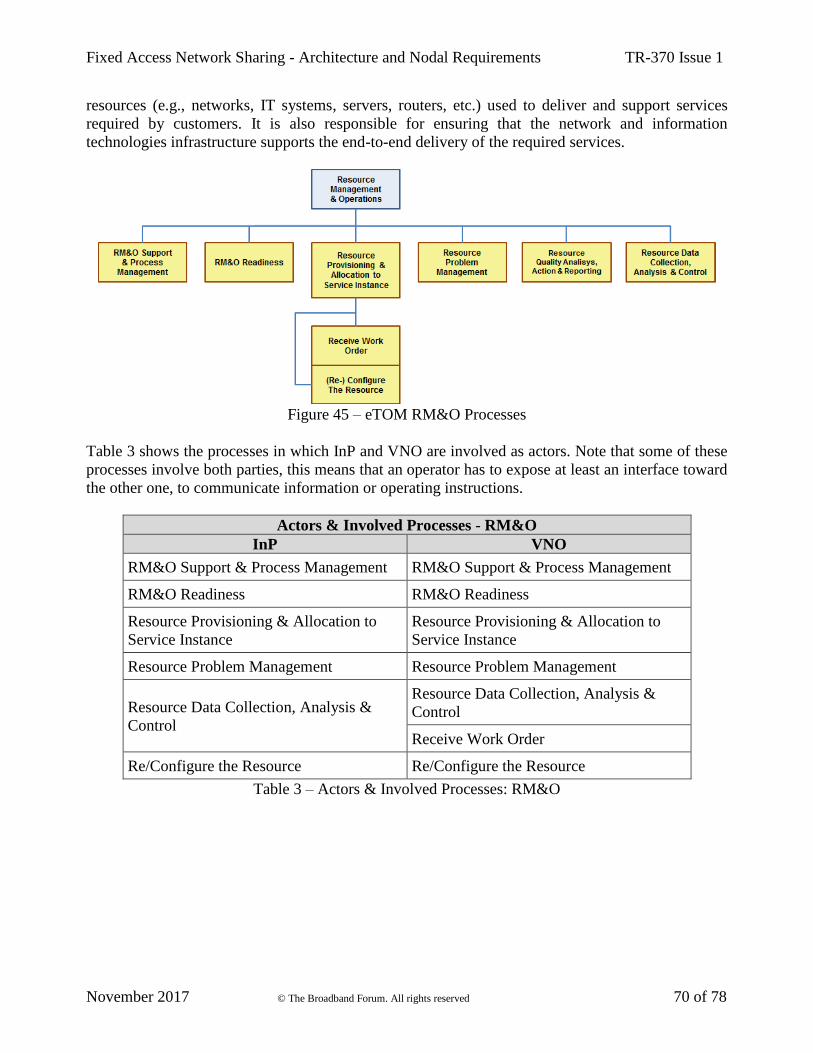
Fixed Access Network Sharing - Architecture and Nodal Requirements TR-370 Issue 1
November 2017 © The Broadband Forum. All rights reserved 70 of 78
resources (e.g., networks, IT systems, servers, routers, etc.) used to deliver and support services
required by customers. It is also responsible for ensuring that the network and information
technologies infrastructure supports the end-to-end delivery of the required services.
Figure 45 – eTOM RM&O Processes
Table 3 shows the processes in which InP and VNO are involved as actors. Note that some of these
processes involve both parties, this means that an operator has to expose at least an interface toward
the other one, to communicate information or operating instructions.
Actors & Involved Processes - RM&O
InP VNO
RM&O Support & Process Management RM&O Support & Process Management
RM&O Readiness RM&O Readiness
Resource Provisioning & Allocation to
Service Instance
Resource Provisioning & Allocation to
Service Instance
Resource Problem Management Resource Problem Management
Resource Data Collection, Analysis &
Control
Resource Data Collection, Analysis &
Control
Receive Work Order
Re/Configure the Resource Re/Configure the Resource
Table 3 – Actors & Involved Processes: RM&O
Fixed Access Network Sharing - Architecture and Nodal Requirements TR-370 Issue 1
November 2017 © The Broadband Forum. All rights reserved 71 of 78
9 Privacy and Security
Privacy involves the need to ensure that information to, from and between customers can only be
accessed by those who have the right to do so. In general, two ways to ensure privacy can be
recognized:
• preventing data, from being copied to a non-intended destination
• encrypting data, so that it cannot be understood even if it is intercepted
Security is a complex issue but many threats can be easily identified. They are based on a risk
assessment of the network, history of attacks against similar networks, or a combination of both. The
overall security solution should include measures for physical security that include anti-theft, anti-
physical-damage, and anti-data-snooping/stealing measures.
In FANS, privacy mainly involves the isolation of end users’ networks and VNOs’ networks. This
means that each end user network and VNO network is isolated from all other networks that are
deployed using the same physical network. InP and VNOs have to adapt their operating procedures
and systems to guarantee the end users’ isolation and to prevent access to an end users network by
unauthorized users. The InP as the owner of the shared infrastructure, must meet the following
requirements:
• guarantee the isolation of the entire infrastructure, preventing access by unauthorized users
• respect the VLAN isolation for the VNOs
This document does not define any specific mechanisms to support lawful intercept, but this feature
is not precluded since FANS maintains backward compatibility with existing architectures.
In Ethernet-based access networks, network security plays a significant role for the network operators.
The FANS architecture does not introduce any additional vulnerabilities over those of standard
Ethernet bridging, at least regarding the physical architecture. The FANS architecture runs on the
physical infrastructure and thus, security relies on the mechanisms used for physical infrastructure,
as defined in TR-101 [2] and TR-178 [3]. Hardware and physical environment security is essential.
If physical security cannot be ensured, attackers may get access to sensitive data by exploiting
vulnerabilities in physical security.
On the other hand, in the FANS virtual Access Node model (5.2.1), the introduction of virtualization
leads to complex security implications, but it can also provide a better isolation of both end users,
VNOs and operators networks.
In practice network virtual partitions have limited vulnerability to outside attacks, since outsiders
cannot inspect or inject packets within a virtual network partition from the outside.
Being based on Ethernet access network, a first level of privacy and security in the FANS architecture
can be established through three approaches, according to what is described in section 5.2.6:
• Operator VLAN (O-VLAN) tunnels
• MPLS tunnels
• VXLAN tunnels

Fixed Access Network Sharing - Architecture and Nodal Requirements TR-370 Issue 1
November 2017 © The Broadband Forum. All rights reserved 72 of 78
These techniques support isolation of the traffic from different VNOs. A VNO can thus maintain its
existing VLAN mapping for its own customer base, solving both privacy and security issues.
It is important to note that in the FANS virtual Access Node model (5.2.1), security aspects have to
be evaluated in a different way compared with traditional networks, since a virtualized environment
could be exposed to external attacks that are not expected within the traditional network architectures.
The introduction of virtualization requires a mix of new and existing solutions for management and
security with common interfaces and mechanisms:
• Network Security – including anti DDoS for vAN, security transport, etc.
• Virtualization System Security – including CPU/memory/disk/IO isolation, hypervisor
scheduling mechanisms, anti-virus system, etc.
• Application Security – including data storage security, login security, management security,
etc.
Security of the Centralized Management System is an important part of the overall security solution
in FANS. To protect it against unauthorized intrusion and misuse, it is essential to restrict user access
to the management interface and enforce access security policies like setting up password restrictions.
Best practice would be to divide into different domains. Domains are defined based on different
service levels for easy management of network security, which shows a clearer structure of the
network. When an attack occurs, it will be isolated in the domain.
Moreover, it is important to cover the security of interfaces. The information exchanged through the
northbound or the southbound interfaces are important and thus should be secured properly.
For this reason, the following aspects need to be considered:
• Authentication
• Authorization (how access rights are determined and managed)
• Privacy
• Auditing (how valid and denied accesses are logged and how these records are made available
to those entitled to access them)
In general, the security of the infrastructure network domain, hypervisor domain, compute domain
and network application domain should leverage the applicable security guidelines outlined in the
existing standards development organizations and industry forums.

Fixed Access Network Sharing - Architecture and Nodal Requirements TR-370 Issue 1
November 2017 © The Broadband Forum. All rights reserved 73 of 78
Appendix I. Access Technologies (Informative)
The scope of this annex is to give some information on how to implement the FANS architecture in
different access technologies, like FTTC/B/dp/H. This helps developers to better understand the
impact of FANS in the different components of the access architecture.
Fibre to the x (FTTx) is a term which represents various optical fiber delivery topologies that are
categorized according to where the fiber terminates in the connection of Subtending Access Nodes.
FTTx specifies the level of penetration of Optical Network Unit (ONU) in the last-mile access
networks. For the scope of the FANS, the following technologies will be considered:
• FTTC (Fibre To The Curb/Cabinet) – It extends the optical infrastructure from the office,
which is typically at the site of the MDF (Main Distribution Frame), to the Street Cabinet (SC)
or to a cluster of them.
• FTTdp (Fibre To The distribution point) – It is very similar to FTTC but in this scenario
the fiber infrastructure terminates closer to the boundary of the customer premise.
• FTTB (Fibre To The Building) – Also this architecture is very similar to FTTC and FTTdp,
where the fiber infrastructure terminates at the basement of a multi-dwelling unit and each
apartment is connected by using existing copper infrastructure.
• FTTH (Fibre To The Home) – It is realized when the fiber network is available directly to
the customer site (e.g., fiber is terminated within the customers apartment or office space). In
this case the ONU is called Optical Network Termination (ONT).
The following Figure 46 depicts a typical legacy access architecture with different FTTx options,
such as FTTCab, FTTB/C and FTTH.
Figure 46 – FTTx Access Network Architecture
A Passive Optical Network (PON) Optical Line Terminator (OLT) provides termination of multiple
customer broadband and telecommunications endpoints and serves as a first-level aggregation point.
Multiple OLTs could be aggregated together by an Ethernet aggregation switch, which in turn
forwards the traffic to a broadband network gateway.

Fixed Access Network Sharing - Architecture and Nodal Requirements TR-370 Issue 1
November 2017 © The Broadband Forum. All rights reserved 74 of 78
In the figure, the reach indicated as “Fibre” represents the Optical Access Network (OAN) and shows
that both ONT/NT and OLT have an interface (respectively UNI and SNI) that depends on which
services are provided by the operator.
The OLT and ONU share the responsibility for Access Node VLAN requirements as specified in TR-
101 [2] and TR-178 [3]. In detail:
• ONU assumes the responsibility of ingress traffic classification for the U interface. ONUs
potentially terminate multiple services and may have different types of U interfaces
• OLT assumes the responsibility of ingress traffic classification for the V interface. The OLT
is the first aggregation point in a PON access scenarios
TR-101 [2]specifies 3 different VLAN architectures:
• Residential/Business 1:1
• Residential/Business N:1
• Business TLS
These models are also supported in FANS scenario. Examples are shown in the following Figure 47,
Figure 48 and Figure 49 in the case of a GPON network.
Figure 47 – FANS 1:1 VLAN Architecture Example
The above Figure 47 depicts a 1:1 VLAN architecture. The ONT maps each 1:1 VLAN into a unique
U interface. The traffic at V interface in upstream direction could be double-tagged or single-tagged:
• For double-tagged VLANs, the ONT:
o can either assign a C-VLAN ID or translate a C-VLAN ID, while the OLT adds the S-
VLAN ID and the O-VLAN ID (Subscriber 1 and Subscriber 4)
o can assign S-C VLAN IDs to incoming traffic, while the OLT adds the O-VLAN ID
and passes through the traffic (Subscriber 2 and Subscriber 5)
• For single-tagged VLAN, the ONT adds the S-VLAN ID or translates an incoming tag to S-
VLAN ID, while the OLT adds the O-VLAN ID and passes through the traffic (Subscriber 3
and Subscriber 6)

Fixed Access Network Sharing - Architecture and Nodal Requirements TR-370 Issue 1
November 2017 © The Broadband Forum. All rights reserved 75 of 78
In the downstream direction, the OLT removes the outer tags or passes through the traffic to proper
GEM port (based on the S-tag value and priority bits). The ONT removes the tags and forwards frames
from the GEM port to its associated U interface.
Figure 48 – FANS N:1 VLAN Architecture Example
For N:1 model, the ONT adds the S-VLAN ID or translate an incoming tag to S-VLAN ID for
upstream traffic. The OLT adds the O-VLAN ID and will pass-through any upstream traffic with S-
VLAN ID on them.
In the downstream direction, the OLT passes through the traffic with O-VLAN ID and S-VLAN ID
to the ONT by determining GEM Port (based on MAC address and priority bits). The ONT will
remove the S-tag and forward frames from the GEM Port to appropriate U interface.
For TLS VLAN model, the ONU maps each U interface into one or more unique S-VLANs. In this
model there are two mutually exclusive methods of subscriber tag assignment:
• Single-tagged, priority-tagged or untagged subscriber packets
• Double-tagged subscriber packets
In the first method a S-Tag is added at the ONU for upstream traffic and is passed through at the OLT,
in addition to the O-VLAN ID added by OLT. In the downstream direction, the OLT passes the packet
through again, and the S-Tag is removed at the ONU before forwarding traffic to the U interface. For
this method, the subscriber can identify optional non-TLS VLANs with specific Q-Tags.
In the second method, frames with valid S-Tags are accepted and may be translated to new values at
the ONU. Frames with invalid S-Tags are silently discarded. In both directions the frames are passed
through the OLT, in addition to the O-VLAN ID added by OLT.
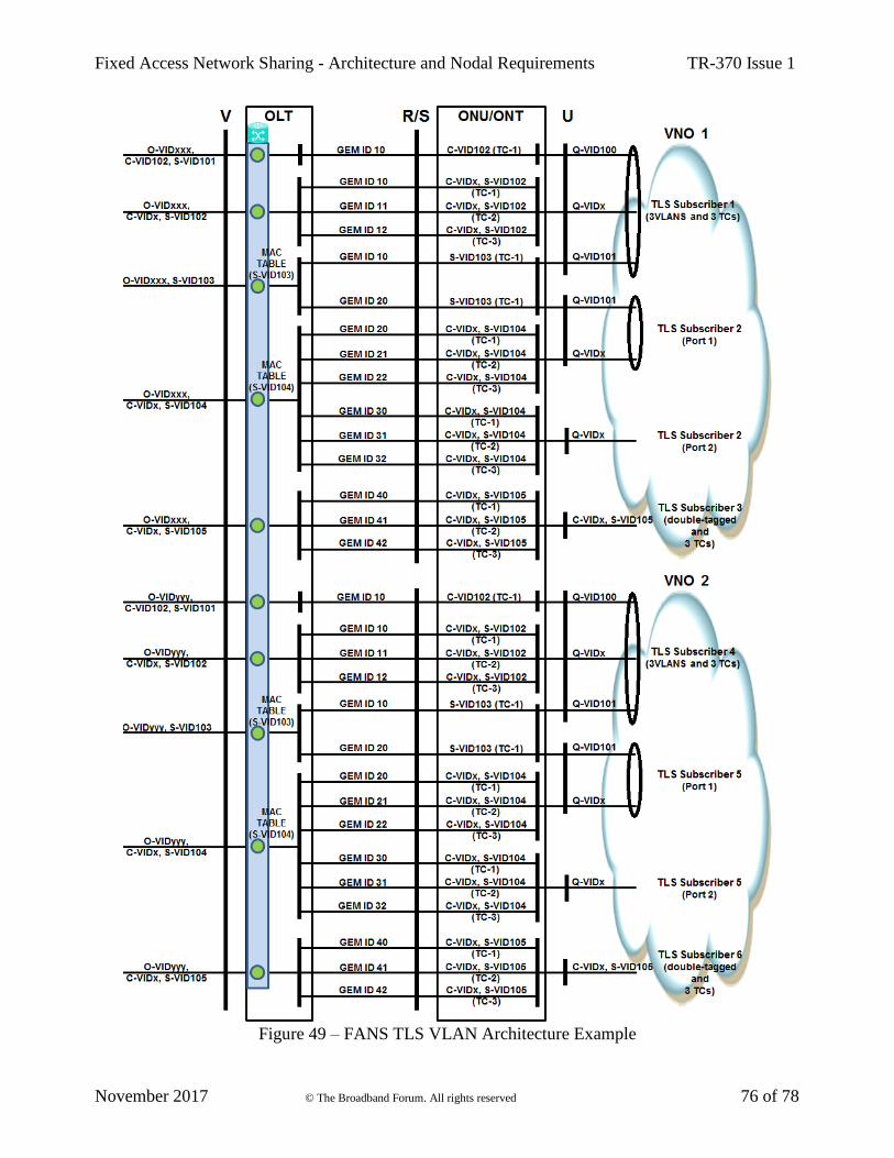
Fixed Access Network Sharing - Architecture and Nodal Requirements TR-370 Issue 1
November 2017 © The Broadband Forum. All rights reserved 76 of 78
Figure 49 – FANS TLS VLAN Architecture Example

Fixed Access Network Sharing - Architecture and Nodal Requirements TR-370 Issue 1
November 2017 © The Broadband Forum. All rights reserved 77 of 78
Figure 50 describes the mapping of physical ports to virtual ports in case of FTTC/FTTdp/FTTB. It
can be noted that in this case the approach is based on Shared ONU as the same ONU includes
connections of multiple virtual operators.
Figure 50 – Customers management in FANS FTTC/FTTdp/FTTB architectures
Figure 51 – Customers management in FANS FTTH architecture
Fixed Access Network Sharing - Architecture and Nodal Requirements TR-370 Issue 1
November 2017 © The Broadband Forum. All rights reserved 78 of 78
As shown in Figure 50, the InP Port Mapper Table contains one-to-one relationships between physical
port IDs and virtual port IDs, while each vAN instance, as mentioned in section 5.2.1, provides similar
functions to those of a physical AN (pAN), thus maintaining information on the customer connected
and the port (virtual) on which the customer is terminated.
Figure 51 describes the mapping of physical ports to virtual ports in case of FTTH. It can be noted
that in this case the approach is based on Dedicated ONU as the each ONU is owned and managed
by a single virtual operator. Thus, the InP Port Mapper Table contains one-to-one relationships
between GEM Port IDs and Virtual Port IDs, while the relationship table for each vAN instance is
similar to the previous case (Shared ONU).
End of Broadband Forum Technical Report TR-370


