18
D/H/HD Series Fixed Displacement Gear Pumps Catalog HY09-D/H/HD/US

D/H/HD Series
Fixed DisplacementGear Pumps
Catalog HY09-D/H/HD/US

3 Parker Hannifin CorporationGear Pump DivisionYoungstown, Ohio USA
Features• Pressure-loaded design
• Efficient, simple design - few moving parts
• Exceptionally compact and lightweight fortheir capacity
• Efficient at high pressure operation
• Resistant to cavitation effects
• High tolerance to system contamination
• Reliable under cold weather operation
• Sleeve-bearing construction
• Multi-fluid compatibility
Pressure capabilities• D - to 2500 PSI (172 Bar) continuous
• H - to 2500 PSI (172 Bar) continuous
• HD - to 2500 PSI (172 Bar) continuous
Controls• Optional built-in relief valve on ''D'' series
• Optional built-in relief valve on ''H'' series
• Optional built-in relief valve, and flow divideron ''H'' series
• Special controls (Consult Technical Services)
Speed capabilities• D - to 4000 RPM
• H - to 4000 RPM
• HD - to 4000 RPM
Catalog HY09-D/H/HD/US
IntroductionFixed Displacement Gear PumpsSeries D/H/HD

4 Parker Hannifin CorporationGear Pump DivisionYoungstown, Ohio USA
A Parker pressure-loaded gear pump consists of two,intermeshing, hardened-steel, precision-ground gearassemblies. These precision gears are enclosed by ahigh-strength, die-cast aluminum front cover, backcover and a high-yield, strength-extruded aluminumcenter section.
Gear assemblies consist of one drive gear, shrink-fitted on a precision-ground and polished driveshaft. This shaft extends outside the pump to permitcoupling to an external prime mover. The secondgear, being the driven gear, is also shrink-fitted on aprecision-ground and polished driven shaft. Retainingrings, which are installed in grooves provided on theshaft, ensure that the gears will not move axially, anda key keeps the drive gear from moving radially.
A lip-type, shaft seal is provided at the drive shaft toprevent external leakage of pump fluid. The sealinglip in contact with the fluid is spring-loaded. Ventpassages within the housings and driven shaftcommunicate pump inlet pressure to the rotary sealarea, thus imposing the lowest possible pressure atthe rotary seal for extended seal life.
The phenolic heat shield, backup gasket, and moldedrubber seal form chambers behind the steel-backedbronze wearplate. These chambers are connectedeither to inlet or discharge pressure. Dischargepressure, acting within the chambers, axially loadsand deflects the wear plate toward the gear faces totake up gear side clearances. This pressure-loadingon the wear plate increases pump efficiency byreducing internal leakage to a minimum, providinglonger pump life.
Pump rotation is dependent upon the properorientation of the heat shield, backup gasket, andrubber seal in the front cover housing, the centersection and rear cover, respectively.
Pumping action is achieved by connecting the pumpdrive shaft to a prime mover, and rotating the gearsaway from the inlet port. Rotation causes the gearmesh to increase on the inlet side and decrease onthe outlet (pressure) side.
Catalog HY09-D/H/HD/US
General DescriptionFixed Displacement Gear PumpsSeries D/H/HD

5 Parker Hannifin CorporationGear Pump DivisionYoungstown, Ohio USA
Catalog HY09-D/H/HD/US
Ordering InformationFixed Displacement Gear PumpsSeries D

6 Parker Hannifin CorporationGear Pump DivisionYoungstown, Ohio USA
Schematic Symbol(Basic Pump)
Installation DataInlet Conditions:
10 in. hg. max. vacuum condition
(At 1800 RPM)
5 in. hg. max. vacuum condition
(At max. RPM)
20 PSI (1.4 Bar) max. positive pressure
Operating Temperature Range:-40°F to 185°F
(-40°C to 85°C)
Filtration:Maintain SAE Class 4
Installation Note:See page 28 for specific recommendations pertainingto system cleanliness, fluids, start-up, inlet conditions,shaft alignment, and other important factors relative tothe proper installation and use of these pumps.
Performance DataSeries D Fixed Displacement, Pressure-LoadedGear Pump
Features• Pressure-loaded design
• Efficient, simple design - few moving parts
• Exceptionally compact and lightweight fortheir capacity
• Efficient at high pressure operation
• Resistant to cavitation effects
• High tolerance to system contamination
• Reliable under cold weather operation
• Sleeve-bearing construction
• Multi-fluid compatibility
Controls• Optional built-in relief valve
• Consult factory for special controls
SpecificationsFlow Ratings:
.5 GPM (1.9 LPM) to 2.7 GPM (10.2 LPM)(At 1000 RPM) See next page for additionalflow data.
Pressure Ratings:D05 thru D22 - 2500 PSI (172 Bar) continuous
D27 - 2000 PSI (138 Bar) continuous
Speed Ratings:D05 thru D22 - 500 to 4000 RPM
D27 - 3000 RPM
Mounting:SAE-AA - 2-Bolt Flange
4-Bolt Flange
Housing Material:Die-Cast Aluminum
Catalog HY09-D/H/HD/US
Technical InformationFixed Displacement Gear PumpsSeries D
7 Parker Hannifin CorporationGear Pump DivisionYoungstown, Ohio USA
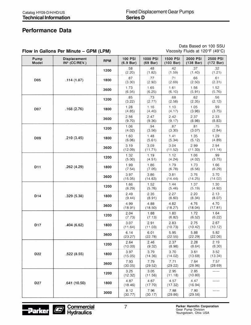
Performance Data
Flow in Gallons Per Minute – GPM (LPM)Data Based on 100 SSU
Viscosity Fluids at 120°F (49°C)
Catalog HY09-D/H/HD/US
Technical InformationFixed Displacement Gear PumpsSeries D

10 Parker Hannifin CorporationGear Pump DivisionYoungstown, Ohio USA
Dimensions – 2-Bolt MountingClockwise rotation and “A” shaft shown(Port locations reverse for CCW rotation)
Front View
Rear View
Side View
Dimensions: Inches (mm)
Catalog HY09-D/H/HD/US
DimensionsFixed Displacement Gear PumpsSeries D

15 Parker Hannifin CorporationGear Pump DivisionYoungstown, Ohio USA
Series H Standard Pumps
Catalog HY09-D/H/HD/US
Ordering InformationFixed Displacement Gear PumpsSeries H

16 Parker Hannifin CorporationGear Pump DivisionYoungstown, Ohio USA
Series H Standard Pumps
Catalog HY09-D/H/HD/US
Ordering InformationFixed Displacement Gear PumpsSeries H

17 Parker Hannifin CorporationGear Pump DivisionYoungstown, Ohio USA
Performance DataSeries H Fixed Displacement, Pressure-LoadedGear Pump
Features• Pressure-loaded design
• Efficient, simple design - few moving parts
• Exceptionally compact and lightweight fortheir capacity
• Efficient at high-pressure operation
• Resistant to cavitation effects
• High tolerance to system contamination
• Reliable under cold weather operation
• Sleeve-bearing construction
• Multi-fluid compatibility
Controls• Optional built-in relief valve
• Optional built-in relief valve and flow divider
• Special controls (Consult Technical Services)
SpecificationsFlow Ratings:
2.5 GPM (9.5 LPM) to 9.3 GPM (35.2 LPM)(At 1000 RPM) See next page for additionalflow data
Pressure Ratings:H25 thru H62 - 2500 PSI (172 Bar) continuous
H77 - 2000 PSI (138 Bar) continuous
H90 - 1500 PSI (103 Bar) continuous
Speed Ratings:H25 thru H49 - 500 to 4000 RPM
H62, H77, H90 - 3600 RPM
Mounting: SAE-A - 2-Bolt Flange
Optional SAE-A - 2-Bolt Flange
Extended Front Cover
Housing Material: Die-Cast Aluminum
Schematic Symbol(Basic Pump)
Installation DataInlet Conditions:
10 in. hg. max. vacuum condition (at 1800 RPM)
5 in. hg. max. vacuum condition (at max. RPM)
20 PSI (1.4 Bar) max. positive pressure
Operating Temperature Range:-40°F to 185°F (-40°C to 85°C)
Filtration:Maintain SAE Class 4
Installation Note:See page 28 for specific recommendationspertaining to system cleanliness, fluids, start-up,inlet conditions, shaft alignment, and otherimportant factors relative to the proper installationand use of these pumps.
Catalog HY09-D/H/HD/US
Technical InformationFixed Displacement Gear PumpsSeries H
18 Parker Hannifin CorporationGear Pump DivisionYoungstown, Ohio USA
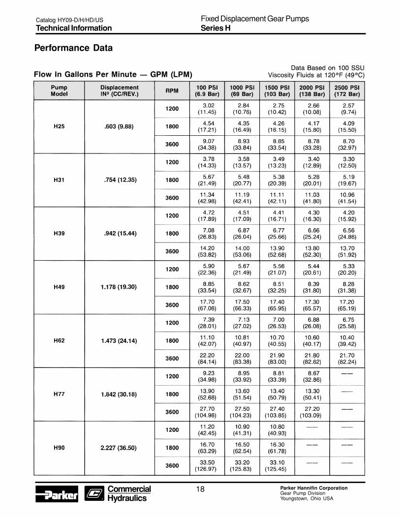
Performance Data
Catalog HY09-D/H/HD/US
Technical InformationFixed Displacement Gear PumpsSeries H

21 Parker Hannifin CorporationGear Pump DivisionYoungstown, Ohio USA
Dimensions – 2-Bolt MountingClockwise rotation and “A” shaft shown(Port locations reverse for CCW rotation.)
Front View
Rear View
Side View
Cover Option
“A” COVER
Dimensions: Inches (mm)
Catalog HY09-D/H/HD/US
DimensionsFixed Displacement Gear PumpsSeries H

22 Parker Hannifin CorporationGear Pump DivisionYoungstown, Ohio USA
Dimensions – 2-Bolt MountingSeries with built-in relief valve and flow dividerClockwise rotation and “A” shaft shown(Port locations reverse for CCW rotation.)
Front View
Rear View
Side View
Circuit Variations
*NOTE: ''D'' Circuit: Relief valve flow and flow divider secondary flow return to pump inlet internally - primarily used in ''on-road'' equipmentpower steering. Relief drain port for ''B'' variation 9/16"-18 UNF-2B SAE Straight Thread.
Dimensions: Inches (mm)
Catalog HY09-D/H/HD/US
DimensionsFixed Displacement Gear PumpsSeries H

23 Parker Hannifin CorporationGear Pump DivisionYoungstown, Ohio USA
Dimensions – Drive Shaft Configurations
"T" Shaft• 3/4" Dia. 11 – tooth spline
• Flat root side fit
• Diametral pitch – 16/32
• Pressure angle – 30°
• No. of teeth – 11
"B" Shaft• 5/8" dia. 9-tooth spline
• Flat root side fit
• Diametral pitch – 16/32
• Pressure angle – 30°
• No. of teeth – 9
Dimensions: Inches (mm)
Catalog HY09-D/H/HD/US
DimensionsFixed Displacement Gear PumpsSeries H

28 Parker Hannifin CorporationGear Pump DivisionYoungstown, Ohio USA
Fluid RecommendationsUse premium-quality hydraulic fluid with operatingviscosity range of 80-1000 SSU. The maximumstart-up viscosity is 4000 SSU. The fluid should havemaximum anti-wear properties, rust and oxidationtreatment.
FiltrationFor maximum pump and systemcomponent life, the system should beprotected from contamination at a levelnot to exceed 125 particles greater than10 microns per milliliter of fluid (SAE Class 4).
Fluid Compatibility• Petroleum-based fluid
• Water glycols
• Water emulsions
• Transmission fluid
• Mineral oil fluid
NOTE: All data in this catalog are based onpetroleum-based fluid. Pump pressure reducedby 1/2 of specified rating; pump speed rating, re-duced by 1000 RPM from specified rating and''DU'' bushings must be used when pump operateson water glycols and water emulsions. Consultthe factory for special fluids.
Start-UpOn any start-up, where the pump suction line isempty of fluid, the circuit should be open to permitpriming.
Inlet ConditionsConditioning should not exceed 10 in. Hg. at 1800RPM or 5 in. Hg. at pump maximum rated RPM. Inletpositive pressure should not exceed 20 PSI(1.4 Bar) maximum.
Shaft Rotation And Line UpPump and motor shaft alignment must be within .007inches total indicator reading. Please follow thecoupling manufacturer's recommended installationinstructions to prevent end thrust on the pump shaft.Turn the pump by hand to assure freedom of rotation.The pump and motor must be on a rigid base.
The coupling should be sized to absorb the peakhorsepower generated.
Installation And MountingThe mounting position is not restricted.
Special InstallationsConsult your Parker representative for any applicationrequiring the following:
• Pressure above rated
• Drive speed above maximum
• Indirect drive
• Fluids other than those specified
• Fluid temperature above 185° F. (85° C.).
Catalog HY09-D/H/HD/US
Fluid RecommendationsFixed Displacement Gear PumpsSeries D/H/HD

29 Parker Hannifin CorporationGear Pump DivisionYoungstown, Ohio USA
Instructions for Reversing GearPump RotationThe basic tools needed are a vise, preferably with softjaws, a torque wrench, a thin screwdriver, a small honestone, a ratchet and a paper clip. The ''D'' series willrequire a 1-1/2'' socket; the ''H'' series an additional1/4'' hex head driver. It is also recommended that youhave extra heat shields and gaskets on hand. Partnumbers are 655287 and 655288 for the ''HD'' series;656942 and 656943 for ''H'' series.
To change rotation, hold the pump by the rear coverwith the drive shaft pointing up. Remove all the bolts.The "HD'' series will have four hex heads, and the ''H''series will have six hex and two alien heads. For futurereference, it would be helpful to scribe a line down theoutlet side of the pump. If you choose not to mark it,the outlet port is usually the smallest.
If the pump has a key-type shaft, remove the key andhone down any burrs that may be on the shaft. This isimportant as the next step will be to lift off the frontcover, and any sharp edges could possibly damagethe front seal or bearing.
After the front cover is off, note the position of the littlevent hole in the bronze wear plate, which should havecome off with the front cover. The parts underneathalso have a similar vent hole.
Remove in order, the wear plate, the heat shield, thegasket, and the V-seal. To facilitate this, make a smallhook with a paper clip and lift the part high enough toslip a screwdriver under it and carefully pry up. Pleasenote that the heat shield, in particular, is very brittleand may crack if bent.
After removing these four parts, reinstall the V-sealwith the lips down in the front cover so that the venthole is on the opposite side across from the referencemark. Use the screwdriver to seat it completely. Next,install the gasket, heat shield, and wear plate; againwith the vent hole in line with that of the V-seal. Thewear plate should be almost flush with the surface ofthe front cover.
Remove the center section and note the notch cut onthe inside. This will be installed in line and next to thevent hole in the wear plate. The dowel pins used tolocate the center section may be removed temporarilyto facilitate sliding the center section over the gearassemblies. Be careful not to pinch the O-ring betweenthe front cover and center section. If it doesn't want tostay in place, it can be ''glued'' using heavy grease.
If the pump is an " H '' series, install the thrust plateinto the center section, orienting the side with the barin line with the vent hole, ensuring that the bronzeside faces the gears.
The rear cover is installed with the outlet side in linewith the vent hole. The outlet side will be marked orcan be identified by the smaller, internal cavity. Aswhen installing the center section, be careful not topinch the O-ring seal.
The line that was originally scribed on the side shouldnow be located at 180° on both the rear cover andcenter section from that on the front cover.
Install the bolts and tighten down by hand. Then,torque to the proper setting, alternating from side toside. The correct torque specifications are 190-210''lbs. for the '' D'' and '' H '' series. Reverse or removethe rotation arrow originally stamped on themounting flange.
Testing ProcedureAfter the pump has been reinstalled, run for 2-3minutes before pressurizing. Try to apply pressuregradually for an additional five minutes, but do notpressurize for longer than 5 seconds at a time.
12. Center Section13. Drive Gear Assembly14. Driven Gear Assembly15. Flow Control ("H" Flow Divider Pump only)16. Relief Valve ("H" Flow Divider Pump Only)17. Back Cover18. Thrust Plate (H only)19. Key (Where Required)
1. Shaft Seal 2. Cap Screws 3. Hex Screws 4. Washers 5. Front Cover 6. V-Seal 7. Dowel Pins 8. Gasket 9. Heat Shield10. Wear Plate11. "0" Rings
Catalog HY09-D/H/HD/US
Installation InformationFixed Displacement Gear PumpsSeries D/H/HD

31 Parker Hannifin CorporationGear Pump DivisionYoungstown, Ohio USA
Parker’s CharterTo be a leading worldwide manufacturer of componentsand systems for the builders and users of durablegoods. More specifically, we will design, market andmanufacture products controlling motion, flow andpressure. We will achieve profitable growth throughpremier customer service.
Product InformationNorth American customers seeking product information,the location of a nearby distributor, or repair serviceswill receive prompt attention by calling the ParkerProduct Information Center at our toll-free number:1-800-C-PARKER (1-800-272-7537). In Europe, call00800-C-PARKER-H (00800-2727-5374).
The Fluid ConnectorsGroup designs, manufacturesand markets rigid and flexibleconnectors, and associatedproducts used in pneumaticand fluid systems.
The Hydraulics Groupdesigns, produces andmarkets a full spectrumof hydraulic componentsand systems to buildersand users of industrialand mobile machineryand equipment.
The Automation Groupis a leading supplier ofpneumatic and electro-mechanical componentsand systems to automationcustomers worldwide.
The Seal Group designs,manufactures and distributesindustrial and commercialsealing devices and relatedproducts by providingsuperior quality and totalcustomer satisfaction.
The Filtration Groupdesigns, manufactures andmarkets quality filtrationand clarification products,providing customers withthe best value, quality,technical support, andglobal availability.
The InstrumentationGroup is a global leaderin the design, manufactureand distribution of high-quality critical flowcomponents for worldwideprocess instrumentation,ultra-high-purity, medicaland analytical applications.
About Parker Hannifin CorporationParker Hannifin is a leading global motion-controlcompany dedicated to delivering premier customerservice. A Fortune 500 corporation listed on theNew York Stock Exchange (PH), our componentsand systems comprise over 1,400 product lines thatcontrol motion in some 1,000 industrial and aerospacemarkets. Parker is the only manufacturer to offer itscustomers a choice of hydraulic, pneumatic, andelectromechanical motion-control solutions. OurCompany has the largest distribution network in itsfield, with over 7,500 distributors serving nearly400,000 customers worldwide.
Parker Hannifin Corporation6035 Parkland Blvd.Cleveland, Ohio , US 44124-4141Tel: (216) 896-3000Fax: (216) 896-4000www.parker.com
Parker Hannifin Corporation
The Aerospace Group isa leader in the development,design, manufacture andservicing of control systemsand components for aerospaceand related high-technologymarkets, while achievinggrowth through premiercustomer service.
The Climate & IndustrialControls Group designs,manufactures and marketssystem-control and fluid-handling components andsystems to refrigeration,air-conditioning and industrialcustomers worldwide.

Parker Hannifin CorporationGear Pump Division1775 Logan AvenueYoungstown, OH 44501 USATel: (330) 746-8011Fax: (330) 746-1148www.parker.com/gearpump
Catalog HY09-D/H/HD/US8/02 T&M 5M


![Gear Pump Content - argo-hytos.com€¦ · Gear Pump – Lightline Version Technical Features Nominal Size Parameters Symbol Unit Displacement [cm3] 0,19 0,26 0,38 0,50 0,65 0,75](https://static.documents.pub/doc/80x56/60090533cb17293a5f0866c8/gear-pump-content-argo-hytoscom-gear-pump-a-lightline-version-technical-features.jpg)


