32
D/H/HD Series Fixed Displacement Gear Pumps Catalog HY09-D/H/HD/US
| Date post: | 29-May-2018 |
| Category: |
Documents |
| Upload: | duongkhuong |
| View: | 219 times |
| Download: | 1 times |
D/H/HD Series
Fixed DisplacementGear Pumps
Catalog HY09-D/H/HD/US

2 Parker Hannifin CorporationGear Pump DivisionYoungstown, Ohio USA
Description Page No.
Introduction .............................................................. 3
General Description ................................................. 4
"D" Series
Ordering Information. ............................................ 5
Technical Information......................................... 6-9
Dimensions .................................................... 10-13
Dimensions - Accessories .................................. 14
"H" Series
Ordering Information. ..................................... 15-16
Technical Information..................................... 17-20
Dimensions .................................................... 21-22
Dimensions - Shaft Configuration ...................... 23
FAILURE OR IMPROPER SELECTION OR IMPROPER USE OF THE PRODUCTS AND/OR SYSTEMS DESCRIBED HEREIN OR RELATED ITEMS CAN CAUSE DEATH, PERSONALINJURY AND PROPERTY DAMAGE.
This document and other information from Parker Hannifin Corporation, its subsidiaries and authorized distributors provide product and/or system options for further investigationby users having technical expertise. It is important that you analyze all aspects of your application and review the information concerning the product or system in the currentproduct catalog. Due to the variety of operating conditions and applications for these products or systems, the user, through its own analysis and testing, is solely responsible formaking the final selection of the products and systems and assuring that all performance, safety and warning requirements of the application are met.
The products described herein, including without limitation, product features, specifications, designs, availability and pricing, are subject to change by Parker Hannifin Corporationand its subsidiaries at any time without notice.
WARNING
Copyright 2002, Parker Hannifin Corporation, All Rights Reserved
The items described in this document are hereby offered for sale by Parker Hannifin Corporation, its subsidiaries or its authorized distributors. This offer and its acceptance aregoverned by the provisions stated in the “Offer of Sale”.
Offer of Sale
Catalog HY09-D/H/HD/US
Table of ContentsFixed Displacement Gear PumpsSeries D/H/HD
"HD" Series
Ordering Information. .......................................... 24
Technical Information..................................... 25-27
Fluid Recommendations ........................................ 28
Instructions for Reversing
Gear Pump Rotation .............................................. 29
Offer of Sale ........................................................... 30

3 Parker Hannifin CorporationGear Pump DivisionYoungstown, Ohio USA
Features• Pressure-loaded design
• Efficient, simple design - few moving parts
• Exceptionally compact and lightweight fortheir capacity
• Efficient at high pressure operation
• Resistant to cavitation effects
• High tolerance to system contamination
• Reliable under cold weather operation
• Sleeve-bearing construction
• Multi-fluid compatibility
Pressure capabilities• D - to 2500 PSI (172 Bar) continuous
• H - to 2500 PSI (172 Bar) continuous
• HD - to 2500 PSI (172 Bar) continuous
Controls• Optional built-in relief valve on ''D'' series
• Optional built-in relief valve on ''H'' series
• Optional built-in relief valve, and flow divideron ''H'' series
• Special controls (Consult Technical Services)
Speed capabilities• D - to 4000 RPM
• H - to 4000 RPM
• HD - to 4000 RPM
Catalog HY09-D/H/HD/US
IntroductionFixed Displacement Gear PumpsSeries D/H/HD
4 Parker Hannifin CorporationGear Pump DivisionYoungstown, Ohio USA
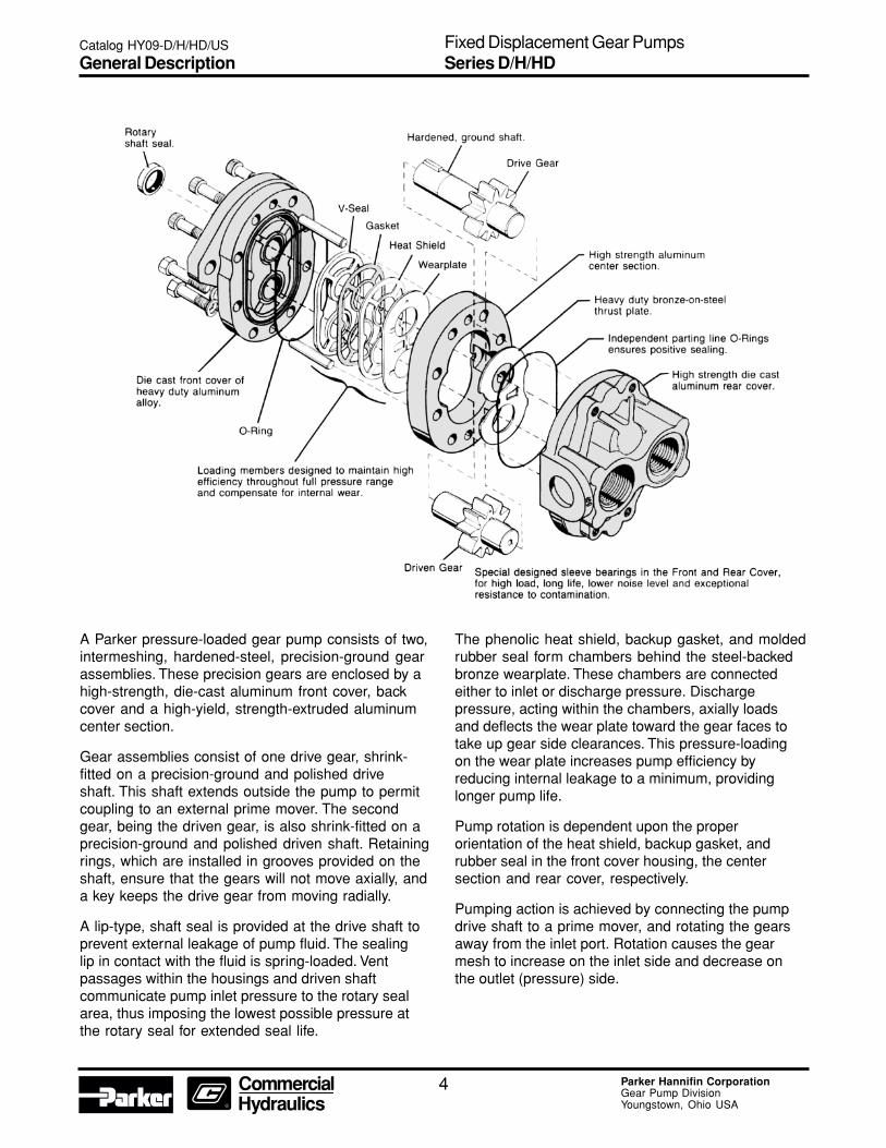
A Parker pressure-loaded gear pump consists of two,intermeshing, hardened-steel, precision-ground gearassemblies. These precision gears are enclosed by ahigh-strength, die-cast aluminum front cover, backcover and a high-yield, strength-extruded aluminumcenter section.
Gear assemblies consist of one drive gear, shrink-fitted on a precision-ground and polished driveshaft. This shaft extends outside the pump to permitcoupling to an external prime mover. The secondgear, being the driven gear, is also shrink-fitted on aprecision-ground and polished driven shaft. Retainingrings, which are installed in grooves provided on theshaft, ensure that the gears will not move axially, anda key keeps the drive gear from moving radially.
A lip-type, shaft seal is provided at the drive shaft toprevent external leakage of pump fluid. The sealinglip in contact with the fluid is spring-loaded. Ventpassages within the housings and driven shaftcommunicate pump inlet pressure to the rotary sealarea, thus imposing the lowest possible pressure atthe rotary seal for extended seal life.
The phenolic heat shield, backup gasket, and moldedrubber seal form chambers behind the steel-backedbronze wearplate. These chambers are connectedeither to inlet or discharge pressure. Dischargepressure, acting within the chambers, axially loadsand deflects the wear plate toward the gear faces totake up gear side clearances. This pressure-loadingon the wear plate increases pump efficiency byreducing internal leakage to a minimum, providinglonger pump life.
Pump rotation is dependent upon the properorientation of the heat shield, backup gasket, andrubber seal in the front cover housing, the centersection and rear cover, respectively.
Pumping action is achieved by connecting the pumpdrive shaft to a prime mover, and rotating the gearsaway from the inlet port. Rotation causes the gearmesh to increase on the inlet side and decrease onthe outlet (pressure) side.
Catalog HY09-D/H/HD/US
General DescriptionFixed Displacement Gear PumpsSeries D/H/HD

5 Parker Hannifin CorporationGear Pump DivisionYoungstown, Ohio USA
Catalog HY09-D/H/HD/US
Ordering InformationFixed Displacement Gear PumpsSeries D

6 Parker Hannifin CorporationGear Pump DivisionYoungstown, Ohio USA
Schematic Symbol(Basic Pump)
Installation DataInlet Conditions:
10 in. hg. max. vacuum condition
(At 1800 RPM)
5 in. hg. max. vacuum condition
(At max. RPM)
20 PSI (1.4 Bar) max. positive pressure
Operating Temperature Range:-40°F to 185°F
(-40°C to 85°C)
Filtration:Maintain SAE Class 4
Installation Note:See page 28 for specific recommendations pertainingto system cleanliness, fluids, start-up, inlet conditions,shaft alignment, and other important factors relative tothe proper installation and use of these pumps.
Performance DataSeries D Fixed Displacement, Pressure-LoadedGear Pump
Features• Pressure-loaded design
• Efficient, simple design - few moving parts
• Exceptionally compact and lightweight fortheir capacity
• Efficient at high pressure operation
• Resistant to cavitation effects
• High tolerance to system contamination
• Reliable under cold weather operation
• Sleeve-bearing construction
• Multi-fluid compatibility
Controls• Optional built-in relief valve
• Consult factory for special controls
SpecificationsFlow Ratings:
.5 GPM (1.9 LPM) to 2.7 GPM (10.2 LPM)(At 1000 RPM) See next page for additionalflow data.
Pressure Ratings:D05 thru D22 - 2500 PSI (172 Bar) continuous
D27 - 2000 PSI (138 Bar) continuous
Speed Ratings:D05 thru D22 - 500 to 4000 RPM
D27 - 3000 RPM
Mounting:SAE-AA - 2-Bolt Flange
4-Bolt Flange
Housing Material:Die-Cast Aluminum
Catalog HY09-D/H/HD/US
Technical InformationFixed Displacement Gear PumpsSeries D
7 Parker Hannifin CorporationGear Pump DivisionYoungstown, Ohio USA
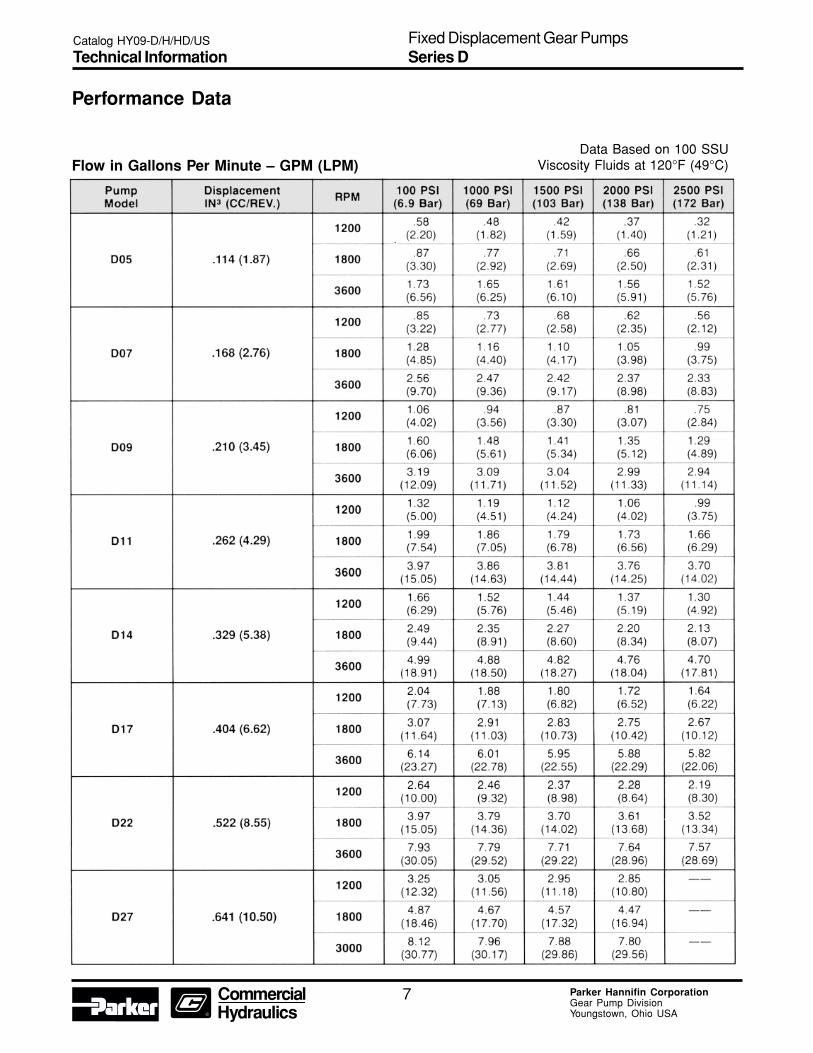
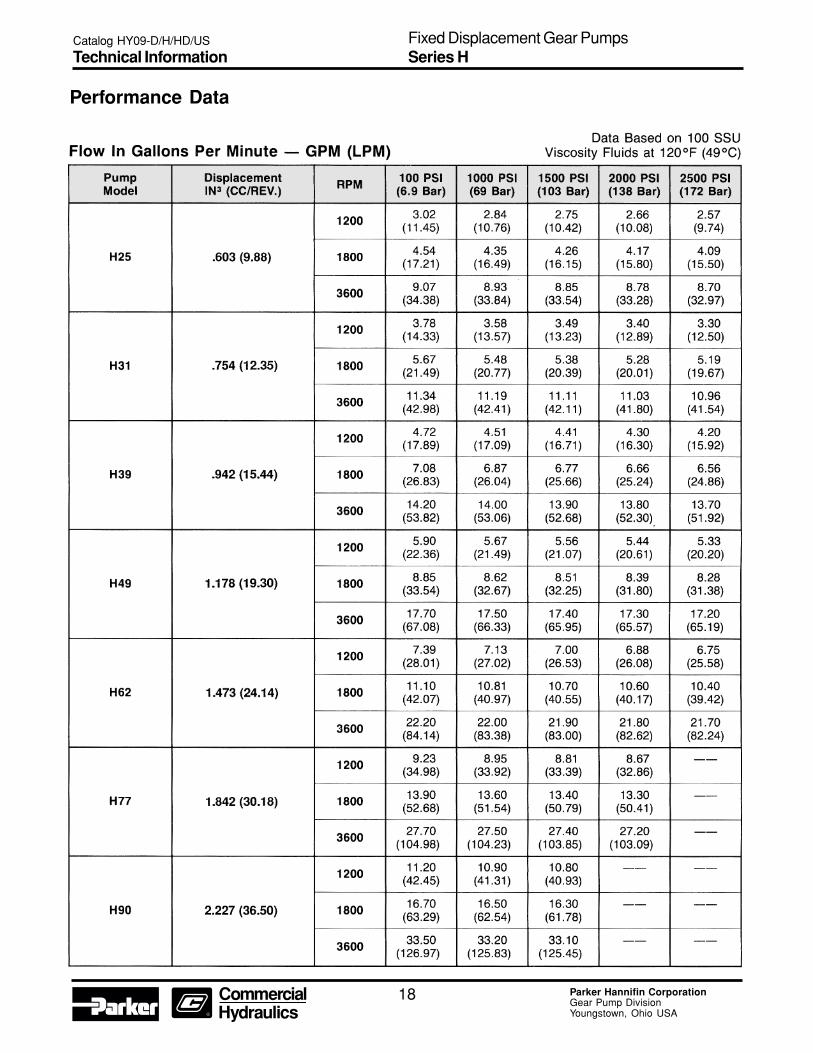
Performance Data
Flow in Gallons Per Minute – GPM (LPM)Data Based on 100 SSU
Viscosity Fluids at 120°F (49°C)
Catalog HY09-D/H/HD/US
Technical InformationFixed Displacement Gear PumpsSeries D
8 Parker Hannifin CorporationGear Pump DivisionYoungstown, Ohio USA
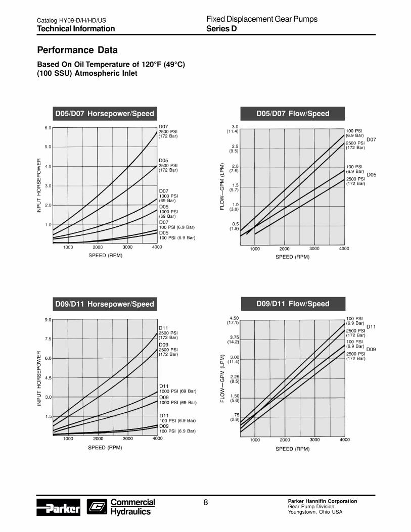
Performance DataBased On Oil Temperature of 120°F (49°C)(100 SSU) Atmospheric Inlet
D09
Catalog HY09-D/H/HD/US
Technical InformationFixed Displacement Gear PumpsSeries D
D09/D11 Horsepower/Speed D09/D11 Flow/Speed
D05/D07 Flow/SpeedD05/D07 Horsepower/Speed
9 Parker Hannifin CorporationGear Pump DivisionYoungstown, Ohio USA
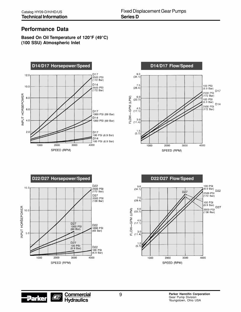
Performance DataBased On Oil Temperature of 120°F (49°C)(100 SSU) Atmospheric Inlet
Catalog HY09-D/H/HD/US
Technical InformationFixed Displacement Gear PumpsSeries D
D14/D17 Flow/SpeedD14/D17 Horsepower/Speed
D22/D27 Flow/SpeedD22/D27 Horsepower/Speed

10 Parker Hannifin CorporationGear Pump DivisionYoungstown, Ohio USA
Dimensions – 2-Bolt MountingClockwise rotation and “A” shaft shown(Port locations reverse for CCW rotation)
Front View
Rear View
Side View
Dimensions: Inches (mm)
Catalog HY09-D/H/HD/US
DimensionsFixed Displacement Gear PumpsSeries D

11 Parker Hannifin CorporationGear Pump DivisionYoungstown, Ohio USA
Dimensions – 4-Bolt MountingClockwise rotation and “A” shaft shown(Port locations reverse for CCW rotation.)
Front View
Side View
Rear
“S” Tang-end Shaft Option – For Use With 4-Bolt MountingPrimarily used to direct-couple to electric motor drive.
Dimensions: Inches (mm)
Catalog HY09-D/H/HD/US
DimensionsFixed Displacement Gear PumpsSeries D
12 Parker Hannifin CorporationGear Pump DivisionYoungstown, Ohio USA
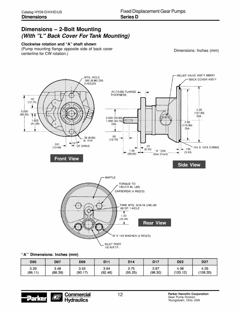
Dimensions – 2-Bolt Mounting(With "L" Back Cover For Tank Mounting)Clockwise rotation and “A” shaft shown(Pump mounting flange opposite side of back covercenterline for CW rotation.)
Side ViewFront View
Rear View
Dimensions: Inches (mm)
Catalog HY09-D/H/HD/US
DimensionsFixed Displacement Gear PumpsSeries D
13 Parker Hannifin CorporationGear Pump DivisionYoungstown, Ohio USA
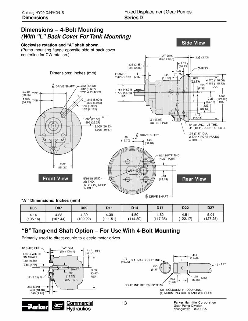
Dimensions – 4-Bolt Mounting(With "L" Back Cover For Tank Mounting)Clockwise rotation and “A” shaft shown(Pump mounting flange opposite side of back covercenterline for CW rotation.)
“B” Tang-end Shaft Option – For Use With 4-Bolt MountingPrimarily used to direct-couple to electric motor drives.
Front View
Side View
Dimensions: Inches (mm)
Catalog HY09-D/H/HD/US
DimensionsFixed Displacement Gear PumpsSeries D
Rear View
14 Parker Hannifin CorporationGear Pump DivisionYoungstown, Ohio USA
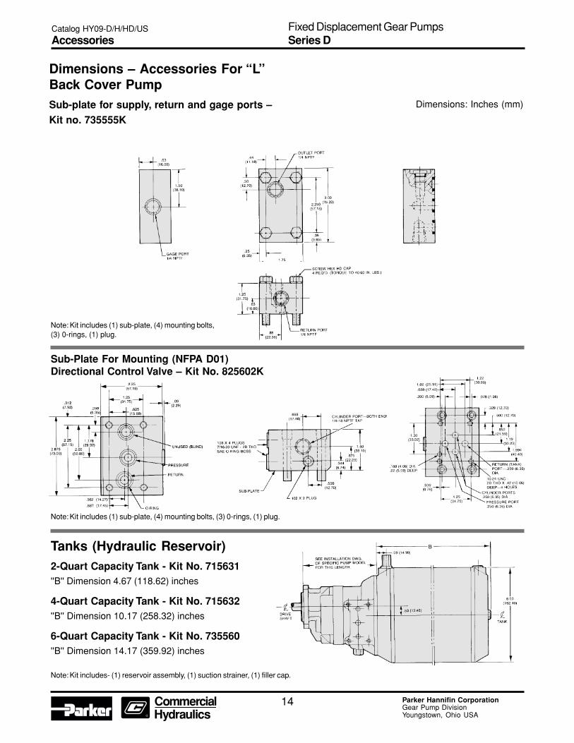
Dimensions – Accessories For “L”Back Cover PumpSub-plate for supply, return and gage ports –Kit no. 735555K
Note: Kit includes (1) sub-plate, (4) mounting bolts,(3) 0-rings, (1) plug.
Sub-Plate For Mounting (NFPA D01)Directional Control Valve – Kit No. 825602K
Tanks (Hydraulic Reservoir)2-Quart Capacity Tank - Kit No. 715631''B'' Dimension 4.67 (118.62) inches
4-Quart Capacity Tank - Kit No. 715632''B'' Dimension 10.17 (258.32) inches
6-Quart Capacity Tank - Kit No. 735560''B'' Dimension 14.17 (359.92) inches
Note: Kit includes- (1) reservoir assembly, (1) suction strainer, (1) filler cap.
Note: Kit includes (1) sub-plate, (4) mounting bolts, (3) 0-rings, (1) plug.
Dimensions: Inches (mm)
Catalog HY09-D/H/HD/US
AccessoriesFixed Displacement Gear PumpsSeries D

15 Parker Hannifin CorporationGear Pump DivisionYoungstown, Ohio USA
Series H Standard Pumps
Catalog HY09-D/H/HD/US
Ordering InformationFixed Displacement Gear PumpsSeries H

16 Parker Hannifin CorporationGear Pump DivisionYoungstown, Ohio USA
Series H Standard Pumps
Catalog HY09-D/H/HD/US
Ordering InformationFixed Displacement Gear PumpsSeries H

17 Parker Hannifin CorporationGear Pump DivisionYoungstown, Ohio USA
Performance DataSeries H Fixed Displacement, Pressure-LoadedGear Pump
Features• Pressure-loaded design
• Efficient, simple design - few moving parts
• Exceptionally compact and lightweight fortheir capacity
• Efficient at high-pressure operation
• Resistant to cavitation effects
• High tolerance to system contamination
• Reliable under cold weather operation
• Sleeve-bearing construction
• Multi-fluid compatibility
Controls• Optional built-in relief valve
• Optional built-in relief valve and flow divider
• Special controls (Consult Technical Services)
SpecificationsFlow Ratings:
2.5 GPM (9.5 LPM) to 9.3 GPM (35.2 LPM)(At 1000 RPM) See next page for additionalflow data
Pressure Ratings:H25 thru H62 - 2500 PSI (172 Bar) continuous
H77 - 2000 PSI (138 Bar) continuous
H90 - 1500 PSI (103 Bar) continuous
Speed Ratings:H25 thru H49 - 500 to 4000 RPM
H62, H77, H90 - 3600 RPM
Mounting: SAE-A - 2-Bolt Flange
Optional SAE-A - 2-Bolt Flange
Extended Front Cover
Housing Material: Die-Cast Aluminum
Schematic Symbol(Basic Pump)
Installation DataInlet Conditions:
10 in. hg. max. vacuum condition (at 1800 RPM)
5 in. hg. max. vacuum condition (at max. RPM)
20 PSI (1.4 Bar) max. positive pressure
Operating Temperature Range:-40°F to 185°F (-40°C to 85°C)
Filtration:Maintain SAE Class 4
Installation Note:See page 28 for specific recommendationspertaining to system cleanliness, fluids, start-up,inlet conditions, shaft alignment, and otherimportant factors relative to the proper installationand use of these pumps.
Catalog HY09-D/H/HD/US
Technical InformationFixed Displacement Gear PumpsSeries H
18 Parker Hannifin CorporationGear Pump DivisionYoungstown, Ohio USA
Performance Data
Catalog HY09-D/H/HD/US
Technical InformationFixed Displacement Gear PumpsSeries H
19 Parker Hannifin CorporationGear Pump DivisionYoungstown, Ohio USA
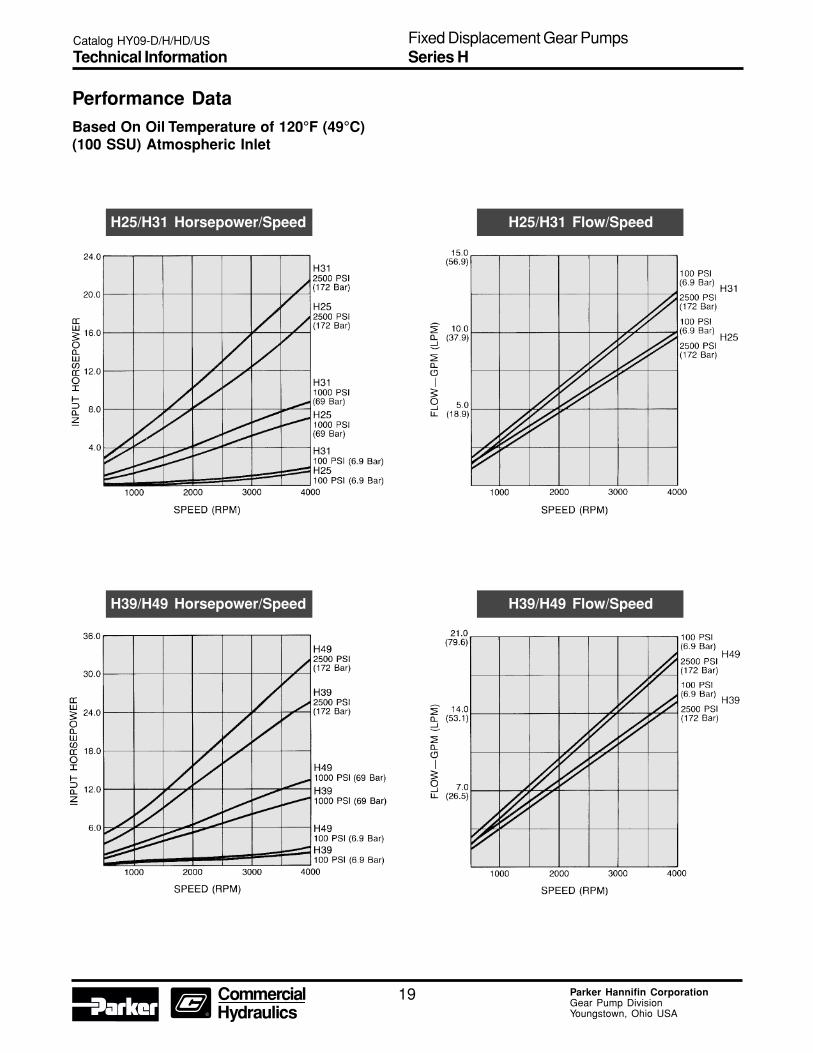
Performance DataBased On Oil Temperature of 120°F (49°C)(100 SSU) Atmospheric Inlet
Catalog HY09-D/H/HD/US
Technical InformationFixed Displacement Gear PumpsSeries H
H25/H31 Flow/SpeedH25/H31 Horsepower/Speed
H39/H49 Flow/SpeedH39/H49 Horsepower/Speed
20 Parker Hannifin CorporationGear Pump DivisionYoungstown, Ohio USA
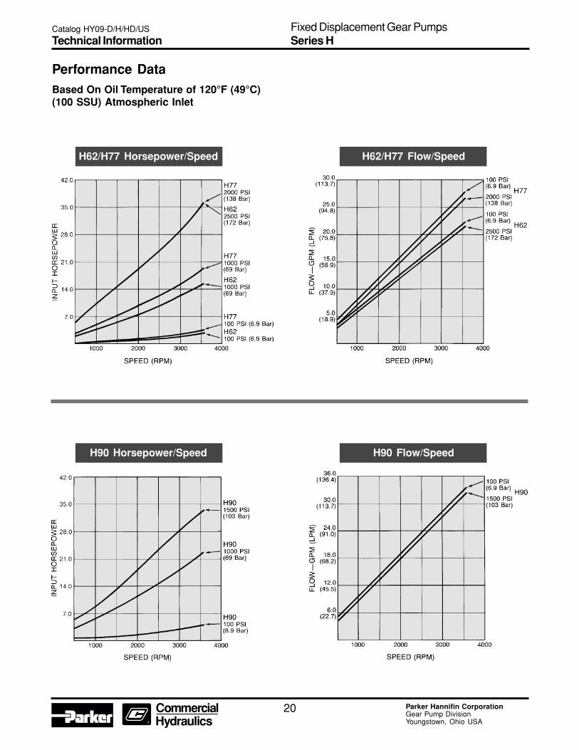
Performance DataBased On Oil Temperature of 120°F (49°C)(100 SSU) Atmospheric Inlet
Catalog HY09-D/H/HD/US
Technical InformationFixed Displacement Gear PumpsSeries H
H62/H77 Flow/SpeedH62/H77 Horsepower/Speed
H90 Flow/SpeedH90 Horsepower/Speed
21 Parker Hannifin CorporationGear Pump DivisionYoungstown, Ohio USA
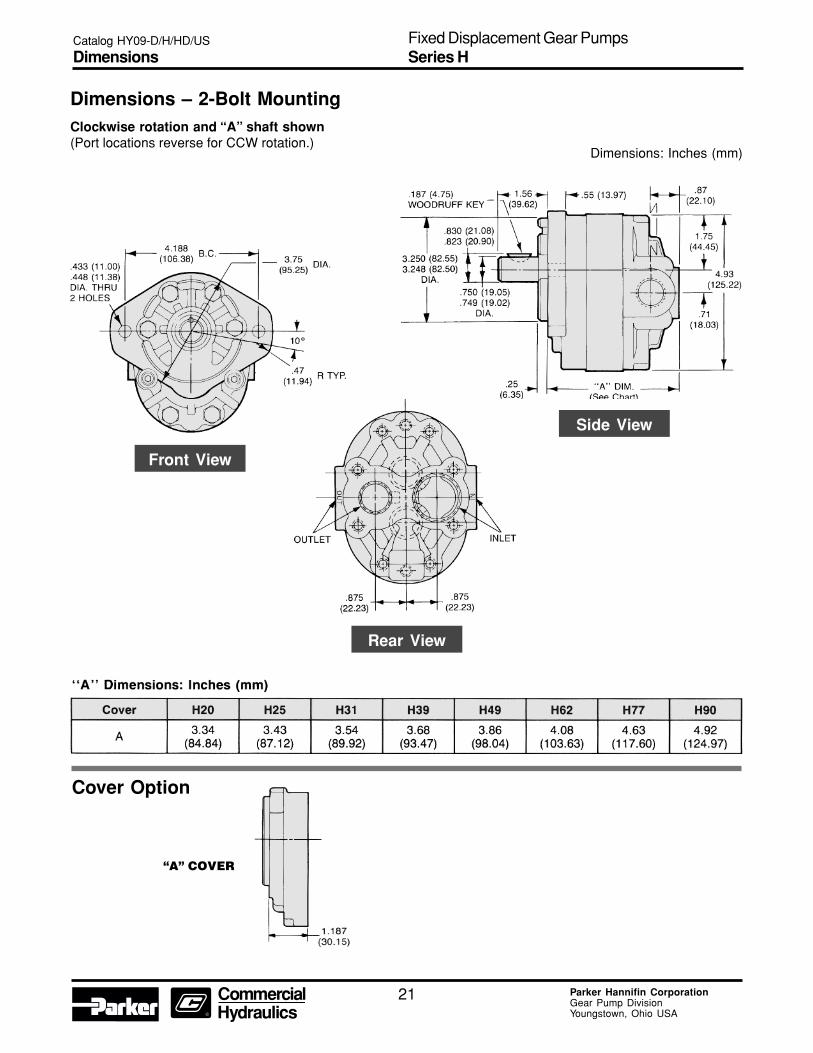
Dimensions – 2-Bolt MountingClockwise rotation and “A” shaft shown(Port locations reverse for CCW rotation.)
Front View
Rear View
Side View
Cover Option
“A” COVER
Dimensions: Inches (mm)
Catalog HY09-D/H/HD/US
DimensionsFixed Displacement Gear PumpsSeries H

22 Parker Hannifin CorporationGear Pump DivisionYoungstown, Ohio USA
Dimensions – 2-Bolt MountingSeries with built-in relief valve and flow dividerClockwise rotation and “A” shaft shown(Port locations reverse for CCW rotation.)
Front View
Rear View
Side View
Circuit Variations
*NOTE: ''D'' Circuit: Relief valve flow and flow divider secondary flow return to pump inlet internally - primarily used in ''on-road'' equipmentpower steering. Relief drain port for ''B'' variation 9/16"-18 UNF-2B SAE Straight Thread.
Dimensions: Inches (mm)
Catalog HY09-D/H/HD/US
DimensionsFixed Displacement Gear PumpsSeries H
23 Parker Hannifin CorporationGear Pump DivisionYoungstown, Ohio USA
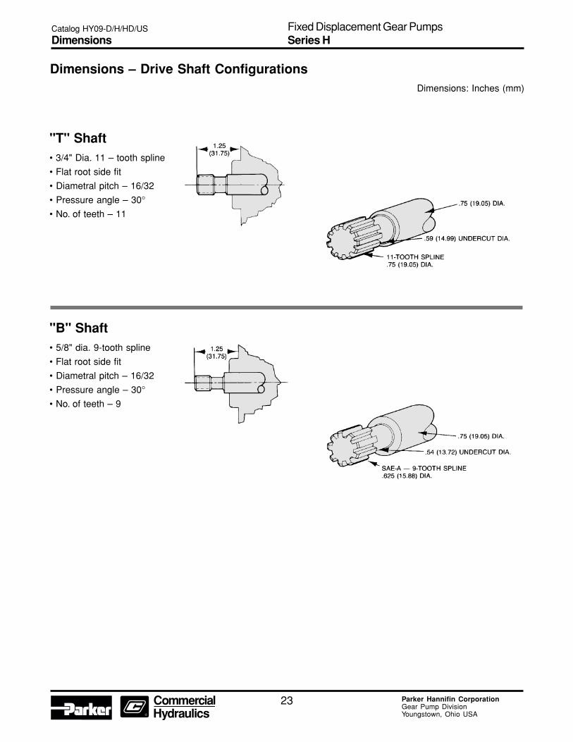
Dimensions – Drive Shaft Configurations
"T" Shaft• 3/4" Dia. 11 – tooth spline
• Flat root side fit
• Diametral pitch – 16/32
• Pressure angle – 30°
• No. of teeth – 11
"B" Shaft• 5/8" dia. 9-tooth spline
• Flat root side fit
• Diametral pitch – 16/32
• Pressure angle – 30°
• No. of teeth – 9
Dimensions: Inches (mm)
Catalog HY09-D/H/HD/US
DimensionsFixed Displacement Gear PumpsSeries H

24 Parker Hannifin CorporationGear Pump DivisionYoungstown, Ohio USA
NOTE:
For additional features or options, please consult thefactory.
Catalog HY09-D/H/HD/US
Ordering InformationFixed Displacement Gear PumpsSeries HD
25 Parker Hannifin CorporationGear Pump DivisionYoungstown, Ohio USA
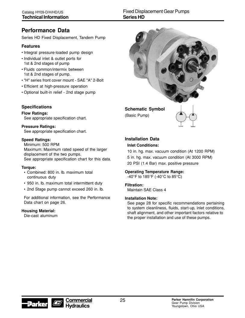
Performance DataSeries HD Fixed Displacement, Tandem Pump
Features• Integral pressure-loaded pump design
• Individual inlet & outlet ports for1st & 2nd stages of pump
• Fluids common/intermix between1st & 2nd stages of pump.
• "H" series front cover mount - SAE "A" 2-Bolt
• Efficient at high-pressure operation
• Optional built-in relief - 2nd stage pump
SpecificationsFlow Ratings:
See appropriate specification chart.
Pressure Ratings:See appropriate specification chart.
Speed Ratings:Minimum: 500 RPMMaximum: Maximum rated speed of the largerdisplacement of the two pumps.See appropriate specification chart for this data.
Torque:• Combined: 800 in. lb. maximum total
continuous duty
• 950 in. lb. maximum total intermittent duty
• 2nd Stage pump cannot exceed 260 in. lb.
For additional information, see the PerformanceData chart on page 26.
Housing Material:Die-cast aluminum
Installation DataInlet Conditions:
10 in. hg. max. vacuum condition (At 1200 RPM)
5 in. hg. max. vacuum condition (At 3000 RPM)
20 PSI (1.4 Bar) max. positive pressure
Operating Temperature Range:-40°F to 185°F (-40°C to 85°C)
Filtration:Maintain SAE Class 4
Installation Note:See page 28 for specific recommendations pertainingto system cleanliness, fluids, start-up, inlet conditions,shaft alignment, and other important factors relative tothe proper installation and use of these pumps.
Schematic Symbol(Basic Pump)
Catalog HY09-D/H/HD/US
Technical InformationFixed Displacement Gear PumpsSeries HD

26 Parker Hannifin CorporationGear Pump DivisionYoungstown, Ohio USA
Performance Data
Combined First and Second stage torque cannot exceed:
800 in. lb. Total continuous duty
950 in. lb. Total intermittent duty
Second stage torque cannot exceed 260 in. lb.
Example:
H39 @ 2500 PSI = 190 in. lb. x 2.5/1000 PSI = 475 in. lb. torque
D17 @ 2500 PSI = 81 in. lb. x 2.5/1000 PSI = 203 in. lb. torque
678 in. lb. total torque
Catalog HY09-D/H/HD/US
Technical InformationFixed Displacement Gear PumpsSeries HD

27 Parker Hannifin CorporationGear Pump DivisionYoungstown, Ohio USA
Performance DataDimensions: Inches (mm)
Front View
Side View
Side ViewRear (CCW) View
Rear View
Catalog HY09-D/H/HD/US
Technical InformationFixed Displacement Gear PumpsSeries HD

28 Parker Hannifin CorporationGear Pump DivisionYoungstown, Ohio USA
Fluid RecommendationsUse premium-quality hydraulic fluid with operatingviscosity range of 80-1000 SSU. The maximumstart-up viscosity is 4000 SSU. The fluid should havemaximum anti-wear properties, rust and oxidationtreatment.
FiltrationFor maximum pump and systemcomponent life, the system should beprotected from contamination at a levelnot to exceed 125 particles greater than10 microns per milliliter of fluid (SAE Class 4).
Fluid Compatibility• Petroleum-based fluid
• Water glycols
• Water emulsions
• Transmission fluid
• Mineral oil fluid
NOTE: All data in this catalog are based onpetroleum-based fluid. Pump pressure reducedby 1/2 of specified rating; pump speed rating, re-duced by 1000 RPM from specified rating and''DU'' bushings must be used when pump operateson water glycols and water emulsions. Consultthe factory for special fluids.
Start-UpOn any start-up, where the pump suction line isempty of fluid, the circuit should be open to permitpriming.
Inlet ConditionsConditioning should not exceed 10 in. Hg. at 1800RPM or 5 in. Hg. at pump maximum rated RPM. Inletpositive pressure should not exceed 20 PSI(1.4 Bar) maximum.
Shaft Rotation And Line UpPump and motor shaft alignment must be within .007inches total indicator reading. Please follow thecoupling manufacturer's recommended installationinstructions to prevent end thrust on the pump shaft.Turn the pump by hand to assure freedom of rotation.The pump and motor must be on a rigid base.
The coupling should be sized to absorb the peakhorsepower generated.
Installation And MountingThe mounting position is not restricted.
Special InstallationsConsult your Parker representative for any applicationrequiring the following:
• Pressure above rated
• Drive speed above maximum
• Indirect drive
• Fluids other than those specified
• Fluid temperature above 185° F. (85° C.).
Catalog HY09-D/H/HD/US
Fluid RecommendationsFixed Displacement Gear PumpsSeries D/H/HD
29 Parker Hannifin CorporationGear Pump DivisionYoungstown, Ohio USA
Instructions for Reversing GearPump RotationThe basic tools needed are a vise, preferably with softjaws, a torque wrench, a thin screwdriver, a small honestone, a ratchet and a paper clip. The ''D'' series willrequire a 1-1/2'' socket; the ''H'' series an additional1/4'' hex head driver. It is also recommended that youhave extra heat shields and gaskets on hand. Partnumbers are 655287 and 655288 for the ''HD'' series;656942 and 656943 for ''H'' series.
To change rotation, hold the pump by the rear coverwith the drive shaft pointing up. Remove all the bolts.The "HD'' series will have four hex heads, and the ''H''series will have six hex and two alien heads. For futurereference, it would be helpful to scribe a line down theoutlet side of the pump. If you choose not to mark it,the outlet port is usually the smallest.
If the pump has a key-type shaft, remove the key andhone down any burrs that may be on the shaft. This isimportant as the next step will be to lift off the frontcover, and any sharp edges could possibly damagethe front seal or bearing.
After the front cover is off, note the position of the littlevent hole in the bronze wear plate, which should havecome off with the front cover. The parts underneathalso have a similar vent hole.
Remove in order, the wear plate, the heat shield, thegasket, and the V-seal. To facilitate this, make a smallhook with a paper clip and lift the part high enough toslip a screwdriver under it and carefully pry up. Pleasenote that the heat shield, in particular, is very brittleand may crack if bent.
After removing these four parts, reinstall the V-sealwith the lips down in the front cover so that the venthole is on the opposite side across from the referencemark. Use the screwdriver to seat it completely. Next,install the gasket, heat shield, and wear plate; againwith the vent hole in line with that of the V-seal. Thewear plate should be almost flush with the surface ofthe front cover.
Remove the center section and note the notch cut onthe inside. This will be installed in line and next to thevent hole in the wear plate. The dowel pins used tolocate the center section may be removed temporarilyto facilitate sliding the center section over the gearassemblies. Be careful not to pinch the O-ring betweenthe front cover and center section. If it doesn't want tostay in place, it can be ''glued'' using heavy grease.
If the pump is an " H '' series, install the thrust plateinto the center section, orienting the side with the barin line with the vent hole, ensuring that the bronzeside faces the gears.
The rear cover is installed with the outlet side in linewith the vent hole. The outlet side will be marked orcan be identified by the smaller, internal cavity. Aswhen installing the center section, be careful not topinch the O-ring seal.
The line that was originally scribed on the side shouldnow be located at 180° on both the rear cover andcenter section from that on the front cover.
Install the bolts and tighten down by hand. Then,torque to the proper setting, alternating from side toside. The correct torque specifications are 190-210''lbs. for the '' D'' and '' H '' series. Reverse or removethe rotation arrow originally stamped on themounting flange.
Testing ProcedureAfter the pump has been reinstalled, run for 2-3minutes before pressurizing. Try to apply pressuregradually for an additional five minutes, but do notpressurize for longer than 5 seconds at a time.
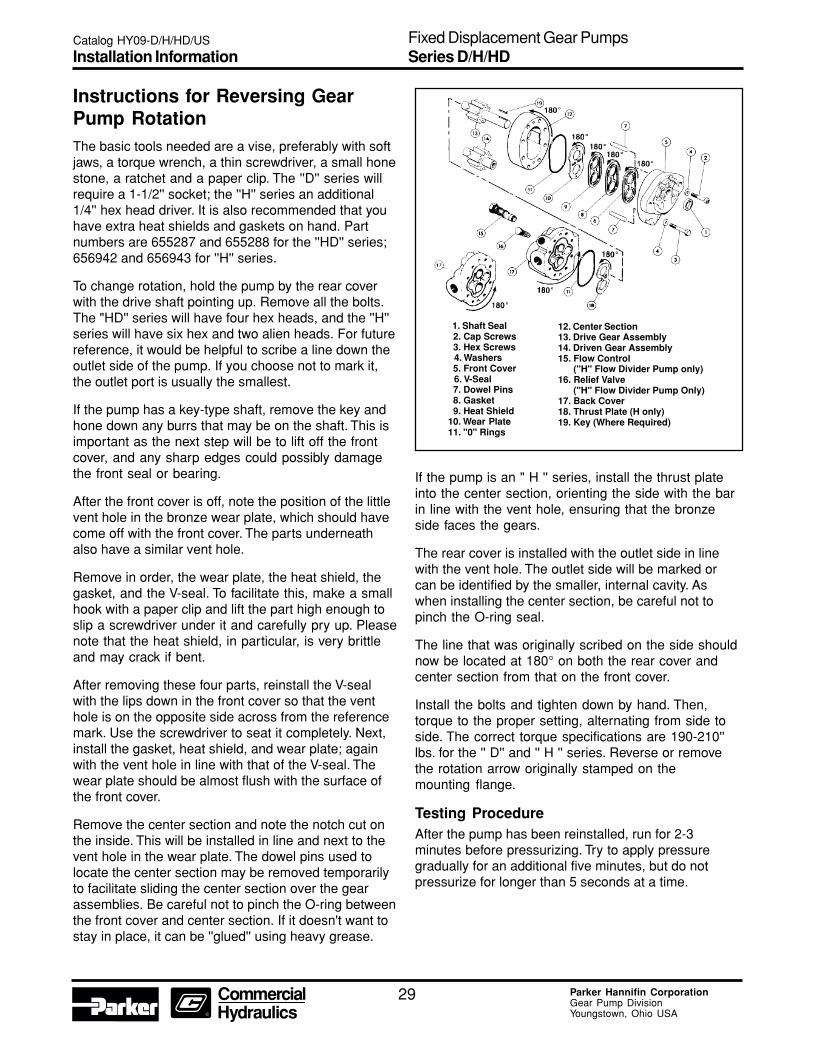
12. Center Section13. Drive Gear Assembly14. Driven Gear Assembly15. Flow Control ("H" Flow Divider Pump only)16. Relief Valve ("H" Flow Divider Pump Only)17. Back Cover18. Thrust Plate (H only)19. Key (Where Required)
1. Shaft Seal 2. Cap Screws 3. Hex Screws 4. Washers 5. Front Cover 6. V-Seal 7. Dowel Pins 8. Gasket 9. Heat Shield10. Wear Plate11. "0" Rings
Catalog HY09-D/H/HD/US
Installation InformationFixed Displacement Gear PumpsSeries D/H/HD

30 Parker Hannifin CorporationGear Pump DivisionYoungstown, Ohio USA
The items described in this document and other documents or descriptions provided by Parker Hannifin Corporation, its subsidiaries and its authorizeddistributors are hereby offered for sale at prices to be established by Parker Hannifin Corporation, its subsidiaries and its authorized distributors. Thisoffer and its acceptance by any customer ("Buyer") shall be governed by all of the following Terms and Conditions. Buyer’s order for any such items,when communicated to Parker Hannifin Corporation, its subsidiary or an authorized distributor ("Seller") verbally or in writing, shall constitute acceptanceof this offer.
1. Terms and Conditions of Sale: All descriptions, quotations, proposals,offers, acknowledgments, acceptances and sales of Seller’s products aresubject to and shall be governed exclusively by the terms and conditionsstated herein. Buyer’s acceptance of any offer to sell is limited to theseterms and conditions. Any terms or conditions in addition to, or inconsistentwith those stated herein, proposed by Buyer in any acceptance of an offerby Seller, are hereby objected to. No such additional, different or inconsis-tent terms and conditions shall become part of the contract between Buyerand Seller unless expressly accepted in writing by Seller. Seller’s accep-tance of any offer to purchase by Buyer is expressly conditional uponBuyer’s assent to all the terms and conditions stated herein, including anyterms in addition to, or inconsistent with those contained in Buyer’s offer,Acceptance of Seller’s products shall in all events constitute such assent.2. Payment: Payment shall be made by Buyer net 30 days from the dateof delivery of the items purchased hereunder. Amounts not timely paidshall bear interest at the maximum rate permitted by law for each month orportion thereof that the Buyer is late in making payment. Any claims byBuyer for omissions or shortages in a shipment shall be waived unlessSeller receives notice thereof within 30 days after Buyer’s receipt of theshipment.3. Delivery: Unless otherwise provided on the face hereof, delivery shallbe made F.O.B. Seller’s plant. Regardless of the method of delivery,however, risk of loss shall pass to Buyer upon Seller’s delivery to a carrier.Any delivery dates shown are approximate only and Seller shall have noliability for any delays in delivery.4. Warranty: Seller warrants that the items sold hereunder shall be freefrom defects in material or workmanship for a period of 18 months from dateof shipment from Parker Hannifin Corporation. THIS WARRANTY COM-PRISES THE SOLE AND ENTIRE WARRANTY PERTAINING TO ITEMSPROVIDED HEREUNDER. SELLER MAKES NO OTHER WARRANTY,GUARANTEE, OR REPRESENTATION OF ANY KIND WHATSOEVER.ALL OTHER WARRANTIES, INCLUDING BUT NOT LIMITED TO, MER-CHANTABILITY AND FITNESS FOR PURPOSE, WHETHER EXPRESS,IMPLIED, OR ARISING BY OPERATION OF LAW, TRADE USAGE, ORCOURSE OF DEALING ARE HEREBY DISCLAIMED.NOTWITHSTANDING THE FOREGOING, THERE ARE NO WARRAN-TIES WHATSOEVER ON ITEMS BUILT OR ACQUIRED WHOLLY ORPARTIALLY, TO BUYER’S DESIGNS OR SPECIFICATIONS.5. Limitation Of Remedy: SELLER’S LIABILITY ARISING FROM OR INANY WAY CONNECTED WITH THE ITEMS SOLD OR THIS CONTRACTSHALL BE LIMITED EXCLUSIVELY TO REPAIR OR REPLACEMENT OFTHE ITEMS SOLD OR REFUND OF THE PURCHASE PRICE PAID BYBUYER, AT SELLER’S SOLE OPTION. IN NO EVENT SHALL SELLERBE LIABLE FOR ANY INCIDENTAL, CONSEQUENTIAL OR SPECIALDAMAGES OF ANY KIND OR NATURE WHATSOEVER, INC.LUDING BUT NOT LIMITED TO LOST PROFITS ARISING FROM OR INANY WAY CONNECTED WITH THIS AGREEMENT OR ITEMS SOLDHEREUNDER, WHETHER ALLEGED TO ARISE FROM BREACH OFCONTRACT, EXPRESS OR IMPLIED WARRANTY, OR IN TORT, IN-CLUDING WITHOUT LIMITATION, NEGLIGENCE, FAILURE TO WARNOR STRICT LIABILITY.6. Changes, Reschedules and Cancellations: Buyer may request tomodify the designs or specifications for the items sold hereunder as wellas the quantities and delivery dates thereof, or may request to cancel allor part of this order, however, no such requested modification or cancel-lation shall become part of the contract between Buyer and Seller unlessaccepted by Seller in a written amendment to this Agreement. Acceptanceof any such requested modification or cancellation shall be at Seller’sdiscretion, and shall be upon such terms and conditions as Seller mayrequire.7. Special Tooling: A tooling charge may be imposed for any specialtooling, including without limitation, dies, fixtures, molds and patterns,acquired to manufacture items sold pursuant to this contract. Such specialtooling shall be and remain Seller’s property notwithstanding payment ofany charges by Buyer. In no event will Buyer acquire any interest inapparatus belonging to Seller which is utilized in the notwithstanding anycharges paid by Buyer. Unless otherwise agreed, Seller shall have theright to alter, discard or otherwise dispose of any special tooling or otherproperty in its sole discretion at any time.
8. Buyer’s Property: Any designs, tools, patterns, materials, drawings,confidential information or equipment furnished by Buyer or any otheritems which become Buyer’s property, may be considered obsolete andmay be destroyed by Seller after two (2) consecutive years have elapsedwithout Buyer placing an order for the items which are manufactured usingsuch property, Seller shall not be responsible for any loss or damage tosuch property while it is in Seller’s possession or control.9. Taxes: Unless otherwise indicated on the face hereof, all prices andcharges are exclusive of excise, sales, use, property, occupational or liketaxes which may be imposed by any taxing authority upon the manufac-ture, sale or delivery of the items sold hereunder. If any such taxes mustbe paid by Seller or if Seller is liable for the collection of such tax, theamount thereof shall be in addition to the amounts for the items sold. Buyeragrees to pay all such taxes or to reimburse Seller therefore upon receiptof its invoice. If Buyer claims exemption from any sales, use or other taximposed by any taxing authority, Buyer shall save Seller harmless from andagainst any such tax, together with any interest or penalties thereon whichmay be assessed if the items are held to be taxable.10. Indemnity For Infringement of Intellectual Property Rights: Sellershall have no liability for infringement of any patents, trademarks, copy-rights, trade dress, trade secrets or similar rights except as provided in thisPart 10. Seller will defend and indemnify Buyer against allegations ofinfringement of U.S. Patents, U.S. Trademarks, copyrights, trade dressand trade secrets (hereinafter ‘Intellectual Property Rights’). Seller willdefend at its expense and will pay the cost of any settlement or damagesawarded in an action brought against Buyer based on an allegation that anitem sold pursuant to this contract infringes the Intellectual Property Rightsof a third party. Seller’s obligation to defend and indemnify Buyer iscontingent on Buyer notifying Seller within ten (10) days after Buyerbecomes aware of such allegations of infringement, and Seller having solecontrol over the defense of any allegations or actions including allnegotiations for settlement or compromise. If an item sold hereunder issubject to a claim that it infringes the Intellectual Property Rights of a thirdparty, Seller may, at its sole expense and option, procure for Buyer the rightto continue using said item, replace or modify said item so as to make itnoninfringing, or offer to accept return of said item and return the purchaseprice less a reasonable allowance for depreciation. Notwithstanding theforegoing, Seller shall have no liability for claims of infringement based oninformation provided by Buyer, or directed to items delivered hereunder forwhich the designs are specified in whole or part by Buyer, or infringementsresulting from the modification, combination or use in a system of any itemsold hereunder. The foregoing provisions of this Part 10 shall constituteSeller’s sole and exclusive liability and Buyer’s sole and exclusive remedyfor infringement of Intellectual Property Rights.If a claim is based on information provided by Buyer or if the design for anitem delivered hereunder is specified in whole or in part by Buyer, Buyershall defend and indemnify Seller for all costs, expenses or judgmentsresulting from any claim that such item infringes any patent, trademark,copyright, trade dress, trade secret or any similar right.11. Force Majeure: Seller does not assume the risk of and shall not beliable for delay or failure to perform any of Seller’s obligations by reason ofcircumstances beyond the reasonable control of Seller (hereinafter ‘Eventsof Force Majeure’). Events of Force Majeure shall include without limita-tion, accidents, acts of God, strikes or labor disputes, acts, laws, rules orregulations of any government or government agency, fires, floods, delaysor failures in delivery of carriers or suppliers, shortages of materials andany other cause beyond Seller’s control.12. Entire Agreement/Governing Law: The terms and conditions set forthherein, together with any amendments, modifications and any differentterms or conditions expressly accepted by Seller in writing, shall constitutethe entire Agreement concerning the items sold, and there are no oral orother representations or agreements which pertain thereto. This Agree-ment shall be governed in all respects by the law of the State of Ohio. Noactions arising out of the sale of the items sold hereunder or this Agreementmay be brought by either party more than two (2) years after the cause ofaction accrues.
9/91-P
Offer of Sale
31 Parker Hannifin CorporationGear Pump DivisionYoungstown, Ohio USA
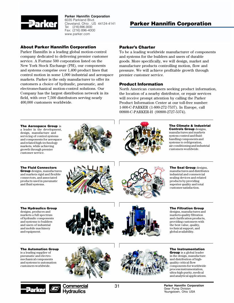
Parker’s CharterTo be a leading worldwide manufacturer of componentsand systems for the builders and users of durablegoods. More specifically, we will design, market andmanufacture products controlling motion, flow andpressure. We will achieve profitable growth throughpremier customer service.
Product InformationNorth American customers seeking product information,the location of a nearby distributor, or repair serviceswill receive prompt attention by calling the ParkerProduct Information Center at our toll-free number:1-800-C-PARKER (1-800-272-7537). In Europe, call00800-C-PARKER-H (00800-2727-5374).
The Fluid ConnectorsGroup designs, manufacturesand markets rigid and flexibleconnectors, and associatedproducts used in pneumaticand fluid systems.
The Hydraulics Groupdesigns, produces andmarkets a full spectrumof hydraulic componentsand systems to buildersand users of industrialand mobile machineryand equipment.
The Automation Groupis a leading supplier ofpneumatic and electro-mechanical componentsand systems to automationcustomers worldwide.
The Seal Group designs,manufactures and distributesindustrial and commercialsealing devices and relatedproducts by providingsuperior quality and totalcustomer satisfaction.
The Filtration Groupdesigns, manufactures andmarkets quality filtrationand clarification products,providing customers withthe best value, quality,technical support, andglobal availability.
The InstrumentationGroup is a global leaderin the design, manufactureand distribution of high-quality critical flowcomponents for worldwideprocess instrumentation,ultra-high-purity, medicaland analytical applications.
About Parker Hannifin CorporationParker Hannifin is a leading global motion-controlcompany dedicated to delivering premier customerservice. A Fortune 500 corporation listed on theNew York Stock Exchange (PH), our componentsand systems comprise over 1,400 product lines thatcontrol motion in some 1,000 industrial and aerospacemarkets. Parker is the only manufacturer to offer itscustomers a choice of hydraulic, pneumatic, andelectromechanical motion-control solutions. OurCompany has the largest distribution network in itsfield, with over 7,500 distributors serving nearly400,000 customers worldwide.
Parker Hannifin Corporation6035 Parkland Blvd.Cleveland, Ohio , US 44124-4141Tel: (216) 896-3000Fax: (216) 896-4000www.parker.com
Parker Hannifin Corporation
The Aerospace Group isa leader in the development,design, manufacture andservicing of control systemsand components for aerospaceand related high-technologymarkets, while achievinggrowth through premiercustomer service.
The Climate & IndustrialControls Group designs,manufactures and marketssystem-control and fluid-handling components andsystems to refrigeration,air-conditioning and industrialcustomers worldwide.

Parker Hannifin CorporationGear Pump Division1775 Logan AvenueYoungstown, OH 44501 USATel: (330) 746-8011Fax: (330) 746-1148www.parker.com/gearpump
Catalog HY09-D/H/HD/US8/02 T&M 5M


