+ All Categories
Home > Documents > Flange Inlet Hydrant Valves

Flange Inlet Hydrant Valves

Date post: 07-Apr-2018
Category:
Upload: arnold-abalos-versoza
View: 229 times
Download: 0 times
Share this document with a friend
3
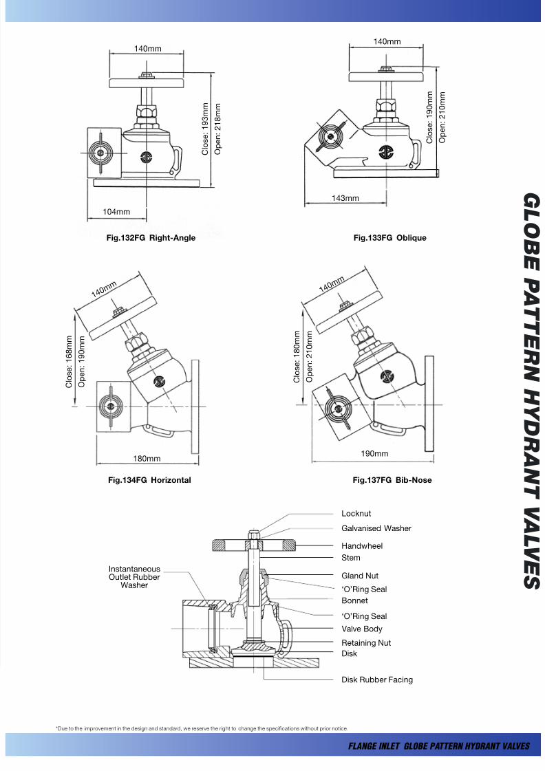
 G L  O  B E P A T T E R N H Y D R A N T V A L V E  S GLOBE PATTERN  HYDRANT V AL VES FLANGE INLET TYPE GENERAL: “AE” range of 65mm diameter “low-pressure” globe pattern hydrant valves with flange inlet connection comes in four different configurations namely, “Oblique”, “Right-Angle”, “Bib-Nose” and “Horizontal” patterns. The design and construction of the hydrant valves are strictly in accordance with BS5041 : Part 1 : 1987 & generally to BS5154 : 1991 standards. The valves are suitable for both on-shore and off-shore fire protection applications. The shut-off of the valve for good water-tight sealing is done by using a high quality rubber bonded seat disc which acts as a primary rubber to metal seal, whilst a secondary metal to metal shut-off is also incorporated in the design of the valve. Every hydrant valve manufactured is hydrostatically tested to 16.5 bars and 22.5 bars for the valve seat and body respectively. The internal casting finishes of every valve is of high quality ensuring a low flow restriction that meets the standard’s water flow test requirement. The hydrant valve comes complete with standard “black” (“Red” is optional) plastic blankcap and chain. Alternative blankcaps made of brass or gunmetal are also available upon request. FLANGE INLET GLOBE PA TTERN HYDRANT VAL VES Fig.137FG Bib-Nose Fig.132FG Right-Angle FEATURES: Compact and elegant design with excellent flow characteristics. High quality cast ing finishes. Primary shut-off by rub ber to metal and a seconda ry metal to metal seating. Corr osion r esist ant and quality materials used for durability, long-life and efficiency. Maintenance fr ee. CONNECTIONS: Inl et : 65mm dia BS4 504 PN1 6 f lat -face flange . Outle t: 65mm BS33 6 female in stan taneo us. Optional inlet flange to BS10 Table D or E flange,  ANSI #150 are available upon request. Fig.134FG Horizontal Fig.133FG Oblique
Transcript

8/4/2019 Flange Inlet Hydrant Valves

http://slidepdf.com/reader/full/flange-inlet-hydrant-valves 1/2

 GL  O B

E P AT T E RN

HY DRANT V 

AL V E  S 

GLOBE PATTERN

 HYDRANT VALVESFLANGE INLET TYPE

GENERAL:

“AE” range of 65mm diameter “low-pressure” globe pattern

hydrant valves with flange inlet connection comes in four

different configurations namely, “Oblique”, “Right-Angle”,

“Bib-Nose” and “Horizontal” patterns.

The design and construction of the hydrant valves are

strictly in accordance with BS5041 : Part 1 : 1987 & generally

to BS5154 : 1991 standards. The valves are suitable for

both on-shore and off-shore fire protection applications.

The shut-off of the valve for good water-tight sealing is

done by using a high quality rubber bonded seat disc which

acts as a primary rubber to metal seal, whilst a secondary

metal to metal shut-off is also incorporated in the design

of the valve.

Every hydrant valve manufactured is hydrostatically tested

to 16.5 bars and 22.5 bars for the valve seat and body

respectively. The internal casting finishes of every valve is

of high quality ensuring a low flow restriction that meets

the standard’s water flow test requirement. The hydrant

valve comes complete with standard “black” (“Red” is

optional) plastic blankcap and chain. Alternative blankcaps

made of brass or gunmetal are also available upon request.

FLANGE INLET GLOBE PATTERN HYDRANT VALVES 

Fig.137FG Bib-Nose

Fig.132FG Right-Angle

FEATURES:

• Compact and elegant design with excellent flow

characteristics.

• High quality casting finishes.

• Primary shut-off by rubber to metal and a secondary

metal to metal seating.

• Corrosion resistant and quality materials used for

durability, long-life and efficiency.

• Maintenance free.

CONNECTIONS:

Inlet : 65mm dia BS4504 PN16 flat-face flange.Outlet : 65mm BS336 female instantaneous.

Optional inlet flange to BS10 Table D or E flange,

 ANSI #150 are available upon request.

Fig.134FG Horizontal

Fig.133FG Oblique

8/4/2019 Flange Inlet Hydrant Valves

http://slidepdf.com/reader/full/flange-inlet-hydrant-valves 2/2

 GL  O B

E P AT T E RN

HY DRANT V 

AL V E  S 

FLANGE INLET GLOBE PATTERN HYDRANT VALVES 

Fig.137FG Bib-Nose

Fig.132FG Right-Angle

*Due to the improvement in the design and standard, we reserve the right to change the specifications without prior notice.

Fig.134FG Horizontal

Fig.133FG Oblique

140mm

   C   l  o  s  e  :

   1   9   3  m  m

   O  p  e  n  :

   2   1   8  m  m

104mm

140mm

   C   l  o

  s  e  :   1   9   0  m  m

   O  p  e  n  :   2   1   0  m  m

143mm

  1 4  0  m

  m

   C   l  o  s  e  :   1   6   8  m  m

   O  p  e  n  :   1   9   0  m  m

180mm

  1 4  0  m

  m

   C   l  o  s  e  :   1   8   0  m  m

   O  p  e  n  :   2   1   0  m  m

190mm

InstantaneousOutlet Rubber

Washer

Locknut

Galvanised Washer

Handwheel

Stem

Gland Nut

‘O’Ring Seal

Bonnet

‘O’Ring Seal

 Valve Body

Retaining Nut

Disk

Disk Rubber Facing


Recommended