FLANGEFORM® Flangeform Clinch Nuts are threaded fasteners with unique ribs de- signed for installation into thin gauge materials. The fastener plunges the pre-punched hole and wraps itself around the material whilst the ribs embed themselves providing an intefgral high strength attachment point. PROCESS ADVANTAGES HOLE PREPERATION—A pre-punched or drilled hole is required with a tolerance of +/- 0.1mm. Refer to product data sheet for hole sizes. SHEET PREPERATION— Flangeform is suited up to 80Rb. SHEET THICKNESS—Refer to the product data sheet for material thickness range INSTALLATION—Can be used on progression, transfer, off-line mechanical / hydraulic presses using autofed or manual technique. TOOLING—Mini-Die (bottom tool) will vary depending upon the material thickness, hole size and hardness High strength attachment point in thin materials Accurate & positive positioning High bending moment resistance One fastener type per size covering material thickness range Pull & push out strength is of similar performance, Provides a flush mounting surface No weld splatter / fumes—environmentally friendly process Can be installed into 2 layers of material Ideally suited to multiple insertion and automated assembly in die or off line. Material is placed over the mini-die and radially located on the pin Force is applied to the nut/stud which enables it to plunge the material Wrapping Installed The nut/stud is formed around the parent material by the profile of the mini-die. The nut is flush and integral with the component Plunging Location
Transcript
FLANGEFORM®
Flangeform Clinch Nuts are threaded fasteners with unique ribs de-
signed for installation into thin gauge materials. The fastener plunges
the pre-punched hole and wraps itself around the material whilst the
ribs embed themselves providing an intefgral high strength attachment
point.
PROCESS
ADVANTAGES
HOLE PREPERATION—A pre-punched or drilled hole is required with a tolerance of +/- 0.1mm. Refer to product
data sheet for hole sizes.
SHEET PREPERATION— Flangeform is suited up to 80Rb.
SHEET THICKNESS—Refer to the product data sheet for material thickness range
INSTALLATION—Can be used on progression, transfer, off-line mechanical / hydraulic presses using autofed or
manual technique.
TOOLING—Mini-Die (bottom tool) will vary depending upon the material thickness, hole size and hardness
High strength attachment point in thin materials
Accurate & positive positioning
High bending moment resistance
One fastener type per size covering material thickness range
Pull & push out strength is of similar performance,
Provides a flush mounting surface
No weld splatter / fumes—environmentally friendly process
Can be installed into 2 layers of material
Ideally suited to multiple insertion and automated assembly in die or off line.
Material is placed
over the mini-die
and radially located
on the pin
Force is applied to
the nut/stud which
enables it to plunge
the material
Wrapping Installed
The nut/stud is
formed around the
parent material by
the profile of the
mini-die.
The nut is flush and
integral with the
component
Plunging Location
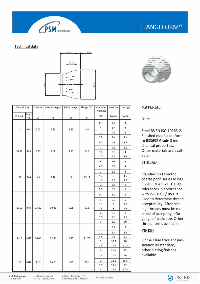
Thread Size Can Dia. Overall Height Spline Length Flange Dia. Material Thickness
Hole Size Tonnage
Unified Met-
ric A B D E mm Typical Typical
- M4 6.63 5.13 2.85 8.8
0.7 4.6 3
1 4.6 3
1.2 4.6 3
1.5 4.7 3.5
10-32 M5 8.25 7.68 4.25 10.9
0.7 4.8 3.5
1 4.8 3.5
1.2 5.5 4
1.5 5.7 4.5
2 5.8 5
1/4 M6 9.9 9.18 5 13.17
0.7 5.1 4
1 5.1 4
1.2 5.9 4.5
1.5 6.5 5.5
2 6.5 6
2.5 6.6 8
5/16 M8 13.29 10.85 5.65 17.6
0.7 6.9 5
1 6.9 5
1.2 8 5.5
1.5 8 7.5
2 8.5 8
2.5 8.6 9.5
3 8.9 10
7/16 M10 16.48 12.58 6.45 21.75
1 9.4 8
1.2 9.4 8.5
1.5 10 9.5
2 10.3 10
2.5 11.4 11.5
3 11.6 12
1/2 M12 19.9 16.23 8.75 26.3
1.5 11.1 16
2 12.1 16.5
2.5 13.1 17
3 13.1 17.5
MATERIAL
Nuts
Steel BS EN ISO 10263-2. Finished nuts to conform to BS3692 Grade 8 me-chanical properties. Other materials are avail-able.
THREAD
Standard ISO Mectric coarse pitch series to ISO 965/BS 3643-6H . Gauge tolerances in accordance with ISO 1502 / BS919 used to determine thread acceptability. After plat-ing, threads must be ca-pable of accepting a Go gauge of basic size. Other thread forms available.
FINISH Zinc & Clear trivalent pas-sivation as standard, other plating finishes available
Dim CDim B
Dim
A
Dim D
Dim
E
THREAD SIZE
FLANGEFORM®
Technical data
FLANGEFORM®
INSTALLATION DATA
MINI DIE INSERTION TOOL DIMENSIONS
These dimensions relate to when standard mini –dies are used. Mini-dies can be modified & tailored to cus-
tomer needs to achieve closer A & Z dimensions.
Mini-die tools are specific for each metric / imperial
size of Flangeform nut and material thickness. This
data is required to choose the correct mini-die for the
application.
FLANGEFORM®
HOW TO SPECIFY
Note: The data provided above is for general guidance only and may vary depending upon material, hole size, tonnages & tooling.
For specific advice and data please contact BAS Components technical centre.