58

2009
2
Hava Kanal› Ba¤lant› SistemleriAir Duct Connection System
3
Hava Kanal› Ba¤lant› SistemleriAir Duct Connection System
4
‹ndeksIndex
Hava Kanal› Ba¤lant› Sistemleri • Air Duct Connection System
Tasar›m Esaslar› • Design Fundamentals
Ürünler • Products
Sayfa/Page : 8 - 9Montaj Talimat› / Assembly Instructions
Sayfa/Page : 10HVCA Sertifikasyonu / HVCA Certification
Sayfa/Page : 12 - 18SMACNA Sertifikasyonu / SMACNA Certification
Sayfa/Page : 12 - 18Kanal Bas›nç S›n›flar› / Duct Pressure Classes
Sayfa/Page : 19Yap› Profilleri Tablosu / Duct Reinforcement Table
Sayfa/Page : 32G Klemens / G Clamp
Sayfa/Page : 21Ask› Seçim Tablosu / Hanger Selection Table
Sayfa/Page : 5Tan›t›m Yaz›s› / Introduction
Sayfa/Page : 27 - 31Flanfl Profil Sistemleri / Flange Profile Systems
Sayfa/Page : 34Mastik / Sealant
Sayfa/Page : 33Conta / Gasket
Sayfa/Page : 39Yatay Bas›nç S›n›rlay›c›lar / Horizontal Trust Restraints
Sayfa/Page : 35Yang›na Dayan›kl› Mastik / Fire Resistant Sealant
Sayfa/Page : 40 - 45Esnek Borular / Flexible Ducts
Sayfa/Page : 36 - 38Montaj Elemanlar› / Mounting Elements
Sayfa/Page : 47 - 48Prolink G Kesitli Profiller
Prolink G Cross Section Profiles
Sayfa/Page : 40Konnektör / Connectors
Sayfa/Page : 49Perfore Bantlar / Perforated Bands
Sayfa/Page : 46Prolink C Kesitli ProfillerProlink C Cross Section Profiles
Sayfa/Page : 52Civata ve Somun / Bolt and Nut
Sayfa/Page : 49Trapez Kelepçe / Trapeze Decking Hanger
Sayfa/Page : 50 - 51Dübeller / Anchors
Yard›mc› Malzemeler • Accessories
Sayfa/Page : 54Alt› Köfle Civata
Hexagon Head Bolt
Sayfa/Page : 53Çeflitli Diflli Ba¤lant› Elemanlar›Various Other Connection & Threaded Accessories
Sayfa/Page : 54Alt› Köfle Somun / Hexagon Head Nut
Sayfa/Page : 22 - 23Uygulama Örnekleri / Application Examples
Sayfa/Page : 20Kuvvetlendirici Rot Ölçüleri / Internal Rod Sizes
HVCA Sertifikasyonu / HVCA Certification
5
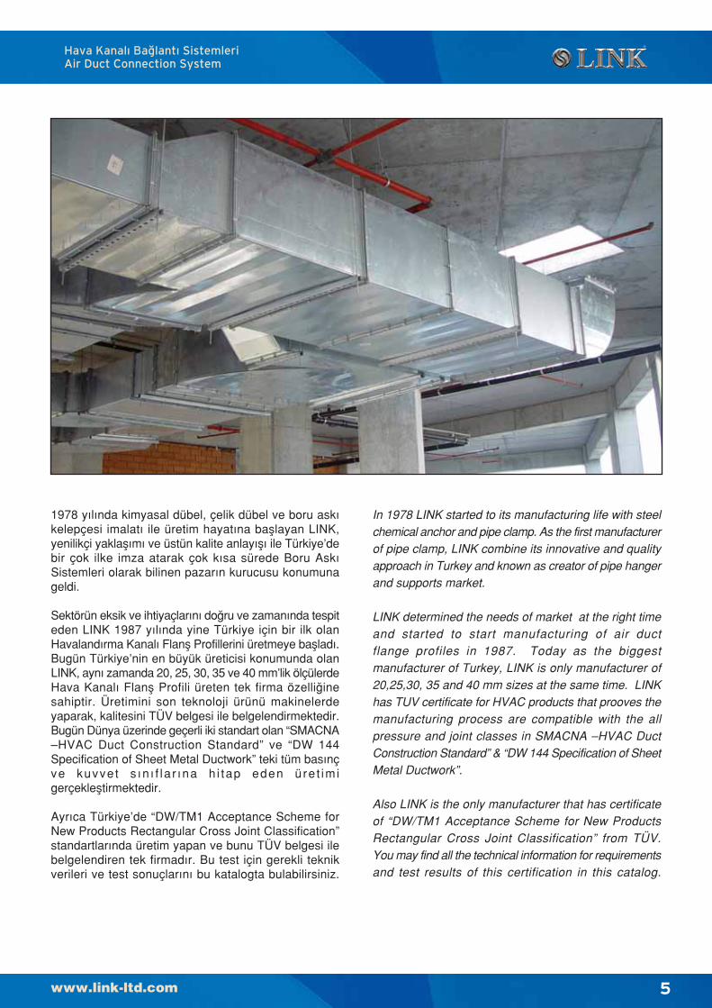
In 1978 LINK started to its manufacturing life with steelchemical anchor and pipe clamp. As the first manufacturerof pipe clamp, LINK combine its innovative and qualityapproach in Turkey and known as creator of pipe hangerand supports market.
LINK determined the needs of market at the right timeand started to start manufacturing of air ductflange profiles in 1987. Today as the biggestmanufacturer of Turkey, LINK is only manufacturer of20,25,30, 35 and 40 mm sizes at the same time. LINKhas TUV certificate for HVAC products that prooves themanufacturing process are compatible with the allpressure and joint classes in SMACNA –HVAC DuctConstruction Standard” & “DW 144 Specification of SheetMetal Ductwork”.
Also LINK is the only manufacturer that has certificateof “DW/TM1 Acceptance Scheme for New ProductsRectangular Cross Joint Classification” from TÜV.You may find all the technical information for requirementsand test results of this certification in this catalog.
1978 yılında kimyasal dübel, çelik dübel ve boru askıkelepçesi imalatı ile üretim hayatına bafllayan LINK,yenilikçi yaklaflımı ve üstün kalite anlayıflı ile Türkiye’debir çok ilke imza atarak çok kısa sürede Boru AskıSistemleri olarak bilinen pazarın kurucusu konumunageldi.
Sektörün eksik ve ihtiyaçlarını do¤ru ve zamanında tespiteden LINK 1987 yılında yine Türkiye için bir ilk olanHavalandırma Kanalı Flanfl Profillerini üretmeye baflladı.Bugün Türkiye’nin en büyük üreticisi konumunda olanLINK, aynı zamanda 20, 25, 30, 35 ve 40 mm’lik ölçülerdeHava Kanalı Flanfl Profili üreten tek firma özelli¤inesahiptir. Üretimini son teknoloji ürünü makinelerdeyaparak, kalitesini TÜV belgesi ile belgelendirmektedir.Bugün Dünya üzerinde geçerli iki standart olan “SMACNA–HVAC Duct Construction Standard” ve “DW 144Specification of Sheet Metal Ductwork” teki tüm basınçve kuvvet s ın ı f la r ına h i tap eden üre t imigerçeklefltirmektedir.
Ayrıca Türkiye’de “DW/TM1 Acceptance Scheme forNew Products Rectangular Cross Joint Classification”standartlarında üretim yapan ve bunu TÜV belgesi ilebelgelendiren tek firmadır. Bu test için gerekli teknikverileri ve test sonuçlarını bu katalogta bulabilirsiniz.
Hava Kanal› Ba¤lant› SistemleriAir Duct Connection System
6
Bu sayfa bilinçli olarak bofl b›rak›lm›flt›r.This pages intentionally left blank
7
Hava Kanal› Ba¤lant› SistemleriAir Duct Connection System
tasar›m esaslar›design fundamentals
8
Montaj Talimat› • Assembly Instructions
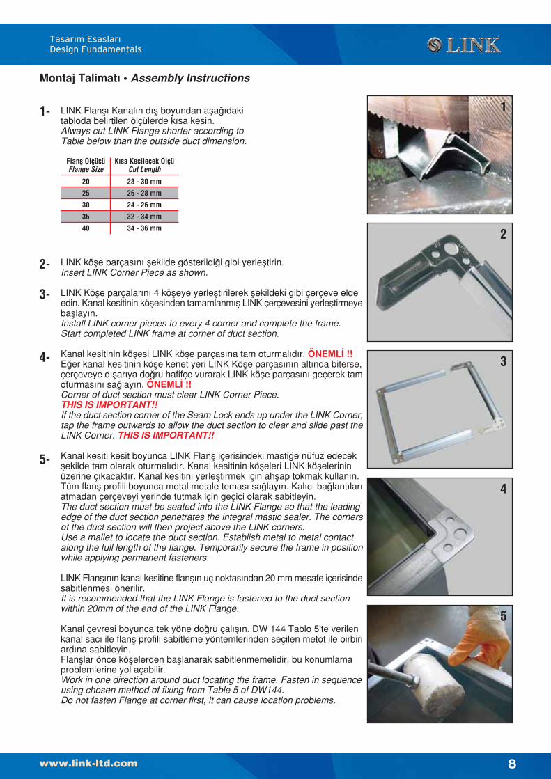
LINK Flanfl› Kanal›n d›fl boyundan afla¤›dakitabloda belirtilen ölçülerde k›sa kesin.Always cut LINK Flange shorter according toTable below than the outside duct dimension.
1- 1
2
3
4
5
2-
3-
4-
5-
LINK köfle parças›n› flekilde gösterildi¤i gibi yerlefltirin.Insert LINK Corner Piece as shown.
LINK Köfle parçalar›n› 4 köfleye yerlefltirilerek flekildeki gibi çerçeve eldeedin. Kanal kesitinin köflesinden tamamlanm›fl LINK çerçevesini yerlefltirmeyebafllay›n.Install LINK corner pieces to every 4 corner and complete the frame.Start completed LINK frame at corner of duct section.
Kanal kesitinin köflesi LINK köfle parças›na tam oturmal›d›r. ÖNEML‹ !!E¤er kanal kesitinin köfle kenet yeri LINK Köfle parças›n›n alt›nda biterse,çerçeveye d›flar›ya do¤ru hafifçe vurarak LINK köfle parças›n› geçerek tamoturmas›n› sa¤lay›n. ÖNEML‹ !!Corner of duct section must clear LINK Corner Piece.THIS IS IMPORTANT!!If the duct section corner of the Seam Lock ends up under the LINK Corner,tap the frame outwards to allow the duct section to clear and slide past theLINK Corner. THIS IS IMPORTANT!!
Kanal kesiti kesit boyunca LINK Flanfl içerisindeki masti¤e nüfuz edecekflekilde tam olarak oturmal›d›r. Kanal kesitinin köfleleri LINK köflelerininüzerine ç›kacakt›r. Kanal kesitini yerlefltirmek için ahflap tokmak kullan›n.Tüm flanfl profili boyunca metal metale temas› sa¤lay›n. Kal›c› ba¤lant›lar›atmadan çerçeveyi yerinde tutmak için geçici olarak sabitleyin.The duct section must be seated into the LINK Flange so that the leadingedge of the duct section penetrates the integral mastic sealer. The cornersof the duct section will then project above the LINK corners.Use a mallet to locate the duct section. Establish metal to metal contactalong the full length of the flange. Temporarily secure the frame in positionwhile applying permanent fasteners.
LINK Flanfl›n›n kanal kesitine flanfl›n uç noktas›ndan 20 mm mesafe içerisindesabitlenmesi önerilir.It is recommended that the LINK Flange is fastened to the duct sectionwithin 20mm of the end of the LINK Flange.
Kanal çevresi boyunca tek yöne do¤ru çal›fl›n. DW 144 Tablo 5'te verilenkanal sac› ile flanfl profili sabitleme yöntemlerinden seçilen metot ile birbiriard›na sabitleyin.Flanfllar önce köflelerden bafllanarak sabitlenmemelidir, bu konumlamaproblemlerine yol açabilir.Work in one direction around duct locating the frame. Fasten in sequenceusing chosen method of fixing from Table 5 of DW144.Do not fasten Flange at corner first, it can cause location problems.
Tasar›m Esaslar›Design Fundamentals
Flanfl ÖlçüsüFlange Size
20
25
30
35
40
K›sa Kesilecek ÖlçüCut Length
28 - 30 mm
26 - 28 mm
24 - 26 mm
32 - 34 mm
34 - 36 mm
9
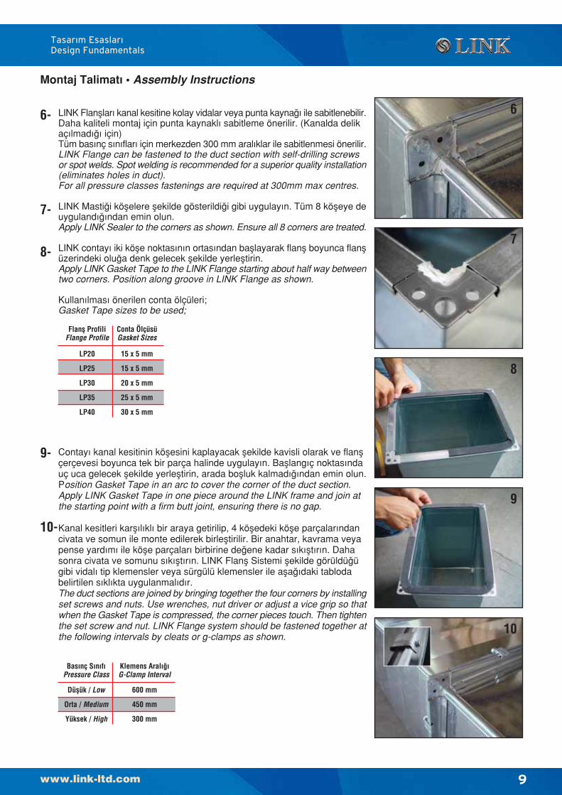
LINK Flanfllar› kanal kesitine kolay vidalar veya punta kayna¤› ile sabitlenebilir.Daha kaliteli montaj için punta kaynakl› sabitleme önerilir. (Kanalda delikaç›lmad›¤› için)Tüm bas›nç s›n›flar› için merkezden 300 mm aral›klar ile sabitlenmesi önerilir.LINK Flange can be fastened to the duct section with self-drilling screwsor spot welds. Spot welding is recommended for a superior quality installation(eliminates holes in duct).For all pressure classes fastenings are required at 300mm max centres.
LINK Masti¤i köflelere flekilde gösterildi¤i gibi uygulay›n. Tüm 8 köfleye deuyguland›¤›ndan emin olun.Apply LINK Sealer to the corners as shown. Ensure all 8 corners are treated.
LINK contay› iki köfle noktas›n›n ortas›ndan bafllayarak flanfl boyunca flanflüzerindeki olu¤a denk gelecek flekilde yerlefltirin.Apply LINK Gasket Tape to the LINK Flange starting about half way betweentwo corners. Position along groove in LINK Flange as shown.
Kullan›lmas› önerilen conta ölçüleri;Gasket Tape sizes to be used;
Montaj Talimat› • Assembly Instructions
6
7
8
9
10
8-
9-
10-
7-
6-
Tasar›m Esaslar›Design Fundamentals
Contay› kanal kesitinin köflesini kaplayacak flekilde kavisli olarak ve flanflçerçevesi boyunca tek bir parça halinde uygulay›n. Bafllang›ç noktas›ndauç uca gelecek flekilde yerlefltirin, arada boflluk kalmad›¤›ndan emin olun.Position Gasket Tape in an arc to cover the corner of the duct section.Apply LINK Gasket Tape in one piece around the LINK frame and join atthe starting point with a firm butt joint, ensuring there is no gap.
Kanal kesitleri karfl›l›kl› bir araya getirilip, 4 köfledeki köfle parçalar›ndancivata ve somun ile monte edilerek birlefltirilir. Bir anahtar, kavrama veyapense yard›m› ile köfle parçalar› birbirine de¤ene kadar s›k›flt›r›n. Dahasonra civata ve somunu s›k›flt›r›n. LINK Flanfl Sistemi flekilde görüldü¤ügibi vidal› tip klemensler veya sürgülü klemensler ile afla¤›daki tablodabelirtilen s›kl›kta uygulanmal›d›r.The duct sections are joined by bringing together the four corners by installingset screws and nuts. Use wrenches, nut driver or adjust a vice grip so thatwhen the Gasket Tape is compressed, the corner pieces touch. Then tightenthe set screw and nut. LINK Flange system should be fastened together atthe following intervals by cleats or g-clamps as shown.
Conta ÖlçüsüGasket Sizes
Flanfl ProfiliFlange Profile
LP20
LP25
LP30
LP35
LP40
15 x 5 mm
15 x 5 mm
20 x 5 mm
25 x 5 mm
30 x 5 mm
Klemens Aral›¤›G-Clamp Interval
Bas›nç S›n›f›Pressure Class
Düflük / Low
Orta / Medium
Yüksek / High
600 mm
450 mm
300 mm
10
Tasar›m Esaslar›Design Fundamentals
Tüm LINK Flanfl Profil Sistemleri
‹ngiliz HVCA - DW/144 – DW/TM1
ve Amerikan SMACNA standartlarına
göre sertikalandırılmıfltır.
HVCA Sertikasyonu
Tüm LINK Flanfl Profilleri HVCA –
Heating and Ventilating Contractors
Association tarafından yayınlanan
“DW 144 Specication of Sheet Metal
Ductwork” standartında ürün
sertikasyonu için atıfta bulunulan
“DW/TM1 Acceptance Scheme for
New Products - Rectangular Cross
Joint Classication” standartına göre
TÜV tarafından sertikalandırılmıfltır.
Buna göre LINK Flanfl Sistemlerinin
DW/144 ve DW/TM1’e göre sınıf
de¤erleri yandaki tabloda verilmifltir.
All LINK Flange Profiles have
certification to British HVCA- DW/144
– DW/TM1 and USA SMACNA
standards.
HVCA Certification
All LINK Flange Profiles are covered
by TÜV certificates and have been
tested to the requirements contained
within the HVCA – Heating and
Ventilating Contractors Association
Standards “DW 144 Specication of
Sheet Metal Ductwork” and
“DW/TM1 Acceptance Scheme for
New Products - Rectangular Cross
Joint Classication”. Joint Rating and
Pressure Classes of LINK Flange
Profiles according to DW/144 and
DW/TM1 are given in the following
tables.
HVCA - DW/144 DW/TM1 Sertifikasyonu / HVCA - DW/144 DW/TM1 Certification
Bas›nç S›n›f› A / Pressure Class A - 500 Pa
Kanal UzunKenar›Duct
LongestSidemm
400
401-600
601-800
801-1000
801-1000
1001-1250
1001-1250
1251-1600
1601-2000
2001-2500
2501-3000
over 3000 üstü
Kal›nl›kThickness
mm
Ba¤lant›S›n›f›Joint
RatingFlanfl
FlangeKuvvetlendirici
Stiffener (1)
0.6
0.8
0.8
0.8
0.8
1.0
1.0
1.0
1.0
1.0
1.2
J2
J2
J2
J2
J3
J2
J3
J3
J4
J5
J5
20 / 25
20 / 25
20 / 25
20 / 25
30 / 35
20 / 25
30 / 35
30 / 35
30 / 35
40
40
S2
S2
S2
S2
S3
S2
S3
S3
S4
S5
S5
KuvvetlendiriciKullanmadan
Mak. BoyMax Length
Without Stiffenermm (2)
3000
3000
1600
1250
1600
625
1250
800
800
800
800
Lütfen Firmam›za Dan›fl›n / Please contact our firm
(1) Kuvvetlendirme s›n›f› için DW144 Sayfa 23, Fig.18-Fig.23 For stiffener rating refer to DW144 Page 23, Fig.18-Fig.23
(2) Bütün maksimum boylar kuvvetlendirilmifl kanallara göre belirtilmifltir.All maxiumum lengths are based on stiffened sheet ducts.
* 40 güçlendirme rotlar› ile / 40 with tie bar
Bas›nç S›n›f› B / Pressure Class B - 1000 Pa400
401-600
601-800
601-800
801-1000
1001-1250
1251-1600
1601-2000
2001-2500
2501-3000
over 3000 üstü
0.6
0.8
0.8
0.8
0.8
1.0
1.0
1.0
1.0
1.2
J2
J2
J2
J3
J3
J3
J4
J5
J5
J5
20 / 25
20 / 25
20 / 25
30 / 35
30 / 35
30 / 35
30 / 35
30 / 35
40
40*
S2
S2
S2
S3
S3
S3
S4
S5
S5
S5
3000
1600
1250
1600
1250
800
800
800
800
625
Lütfen Firmam›za Dan›fl›n / Please contact our firm
Bas›nç S›n›f› C / Pressure Class C - 2000 Pa400
401-600
601-800
801-1000
1001-1250
1251-1600
1601-2000
2001-2500
over 2500 üstü
0.8
0.8
0.8
0.8
1.0
1.0
1.2
1.2
J2
J2
J2
J3
J4
J5
J5
J6
20 / 25
20 / 25
20 / 25
30 / 35
30 / 35
40
40
40*
S2
S2
S2
S3
S4
S5
S5
S6
3000
1250
800
800
800
800
625
625
Lütfen Firmam›za Dan›fl›n / Please contact our firm
11
SMACNA Sertifikasyonu • SMACNA Certification
All LINK Flanges are covered by TÜV certificates and
have been tested to the requirements contained within
the “SMACNA –HVAC Duct Construction Standard”.
Flange size selection table for pressure classes according
to SMACNA are given to
Flange Size Selection Table for Pressure Classes
(Tablo 1-7)
Table Guideline Notes
1- LP 25 = LINK 25 mm Flange Connection System
LP 35 = LINK 35 mm Flange Connection System
2- CTR = Intermediate tie rods in duct, halfway
between duct joints.
3- A,B,C, etc. refer to intermediate reinforcing
between joints as per SMACNA “Duct
Construction Standards” Rigidity Specifications.
4- (*) refer to tie rods at intermediate stiffeners or at
the LINK joint. (JTR)
5- Dimensions indicate maximum distance
between joints or reinforcements.
6- CTR’s to be used for positive pressure applications
only.
Example;
For a 1800 x 300 mm duct @ 500 Pa the contractor has
several options:
He can build 1,8 mt sections from 0,85 mm with LP-35
@ each end and an intermediate reinforcement (CTR
or “H”).
He can also build 0,9 mt sections from 0,85 mm with
LP-35 @ each end and no intermediate reinforcement.
He can build 1,5 mt sections from 0,85 mm or 1,2 mt
sections from 0,70 mm with LP-35 @ each end and an
intermediate reinforcement (CTR or “H”).
Finally, he can build 0,75 mt sections from 0,85 mm or
0,6 mt sections from 0,70 mm with
LP-35 @ each end and no intermediate reinforcement.
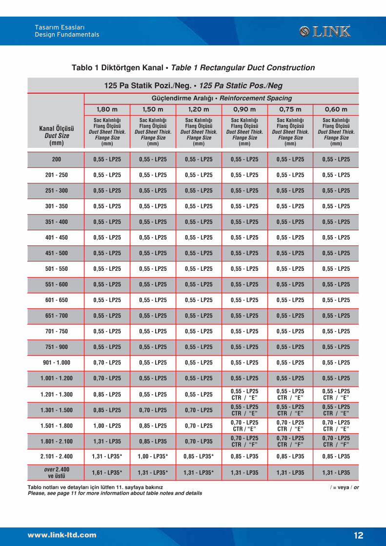
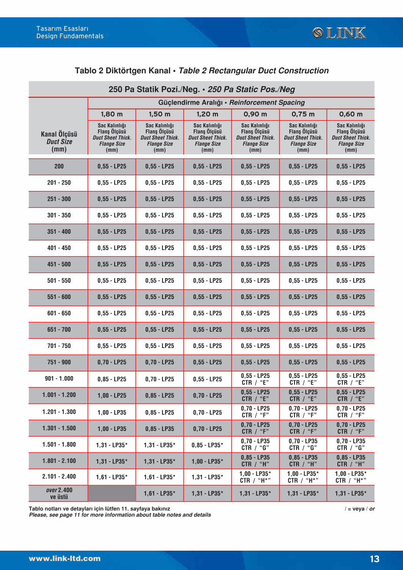
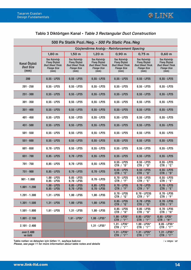
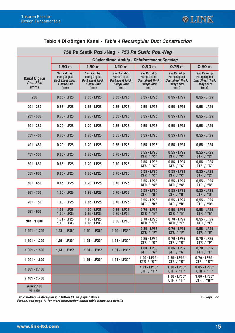
Tüm LINK Flanfl Profil sistemleri “SMACNA –HVAC DuctConstruction Standard” standartlarına göre TÜVtarafından sertifikalandırılmıfltır. SMACNA flartlarınagöre basınç sınıflarına göre Flanfl Seçim Tablosu takipeden sayfalarda, bu tablonun kullanım notları da afla¤ıdaverilmifltir.
Basınç Sınıflarına göre Flanfl Seçim Tablosu(Tablo 1-7)
Tablo Kullanım Notları1- LP 25 = LINK 25 mm Flanfl Profili Sistemi
LP 35 = LINK 35 mm Flanfl Profili Sistemi2- CTR = Kanal birlefltirme noktalarının
ortasına atılan ara ek ba¤lantı rotlarını ifade eder.
3- A,B,C, vb. SMACNA “Hava Kanalı ‹malat Standartı” Sertlik fiartnamelerinde belirtilen Flanfl ba¤lantı noktaları ortasındaki güçlendirme sınıflarını ifade eder.
4- (*) LINK Flanfl Profili üzerindeki veya orta güçlendirici üzerindeki ek ba¤lantı rotlarını ifade eder. (JTR)
5- Ölçüler Flanfl ba¤lantıları veya güçlendiriciler arası maksimum mesafeleri belirtir.
6- CTR’ler sadece pozitif basınç uygulamalarında kullanılmalıdır.
Örnek ;1800 x 300 mm 500 Pa basınçta bir kanal için uygulayıcıbirkaç seçene¤e sahiptir.0,85 mm kalınlıkta bir kanal sacından 1,8 m uzunlu¤undaiki ucunda LP-35 flanfl ve ortasında güçlendirme (CTRveya “H”) ile imal edebilir.veya0,85 mm kalınlıkta bir kanal sacından 0,9 m uzunlu¤undaiki ucunda LP-35 flanfl ile güçlendirmeye gerek olmadanimal edebilir.veya0,85 mm kalınlıkta bir kanal sacından 1,5 m uzunlu¤undaveya 0,70 mm kalınlıkta bir kanal sacından 1,2 muzunlu¤unda iki ucunda LP-35 flanfl sistemi ve ortasındagüçlendirme (CTR veya “H”) ile imal edebilir.ve son olarak0,85 mm kalınlıkta bir kanal sacından 0,75 m uzunlu¤undaveya 0,70 mm kalınlıkta bir kanal sacından 0,6 muzunlu¤unda iki ucunda LP-35 flanfl sistemi ve ortasındagüçlendirmeye gerek olmadan imal edebilir.
Tasar›m Esaslar›Design Fundamentals
Tasar›m Esaslar›Design Fundamentals
12
Tablo notlar› ve detaylar› için lütfen 11. sayfaya bak›n›zPlease, see page 11 for more information about table notes and details
Tablo 1 Diktörtgen Kanal • Table 1 Rectangular Duct Construction
Sac Kal›nl›¤›Flanfl Ölçüsü
Duct Sheet Thick.Flange Size
(mm)
Güçlendirme Aral›¤› • Reinforcement Spacing
125 Pa Statik Pozi./Neg. • 125 Pa Static Pos./Neg
1,50 m 1,20 m 0,90 m 0,75 m 0,60 m
Sac Kal›nl›¤›Flanfl Ölçüsü
Duct Sheet Thick.Flange Size
(mm)
Sac Kal›nl›¤›Flanfl Ölçüsü
Duct Sheet Thick.Flange Size
(mm)
Sac Kal›nl›¤›Flanfl Ölçüsü
Duct Sheet Thick.Flange Size
(mm)
Sac Kal›nl›¤›Flanfl Ölçüsü
Duct Sheet Thick.Flange Size
(mm)
Sac Kal›nl›¤›Flanfl Ölçüsü
Duct Sheet Thick.Flange Size
(mm)
1,80 m
0,55 - LP25 0,55 - LP25 0,55 - LP25 0,55 - LP25 0,55 - LP25 0,55 - LP25
0,55 - LP25 0,55 - LP25 0,55 - LP25 0,55 - LP25 0,55 - LP25 0,55 - LP25
0,55 - LP25 0,55 - LP25 0,55 - LP25 0,55 - LP25 0,55 - LP25 0,55 - LP25
0,55 - LP25 0,55 - LP25 0,55 - LP25 0,55 - LP25 0,55 - LP25 0,55 - LP25
0,55 - LP25 0,55 - LP25 0,55 - LP25 0,55 - LP25 0,55 - LP25 0,55 - LP25
0,55 - LP25 0,55 - LP25 0,55 - LP25 0,55 - LP25 0,55 - LP25 0,55 - LP25
0,55 - LP25 0,55 - LP25 0,55 - LP25 0,55 - LP25 0,55 - LP25 0,55 - LP25
0,55 - LP25 0,55 - LP25 0,55 - LP25 0,55 - LP25 0,55 - LP25 0,55 - LP25
0,55 - LP25 0,55 - LP25 0,55 - LP25 0,55 - LP25 0,55 - LP25 0,55 - LP25
0,55 - LP25 0,55 - LP25 0,55 - LP25 0,55 - LP25 0,55 - LP25 0,55 - LP25
0,55 - LP25 0,55 - LP25 0,55 - LP25 0,55 - LP25 0,55 - LP25 0,55 - LP25
0,55 - LP25 0,55 - LP25 0,55 - LP25 0,55 - LP25 0,55 - LP25 0,55 - LP25
0,70 - LP25 0,55 - LP25 0,55 - LP25 0,55 - LP25 0,55 - LP25 0,55 - LP25
0,55 - LP250,70 - LP25 0,55 - LP25 0,55 - LP25 0,55 - LP25 0,55 - LP25
1,31 - LP35* 1,00 - LP35* 0,85 - LP35* 0,85 - LP35 0,85 - LP35 0,85 - LP35
0,85 - LP25 0,70 - LP25 0,70 - LP25 0,55 - LP25CTR / “E”
0,55 - LP25CTR / “E”
0,55 - LP25CTR / “E”
1,00 - LP25 0,85 - LP25 0,70 - LP25CTR / “E”
0,70 - LP25CTR / “E”0,70 - LP25 0,70 - LP25
CTR / “E”
1,31 - LP35 0,85 - LP35 0,70 - LP25CTR / “F”0,70 - LP35 0,70 - LP25
CTR / “F”0,70 - LP25CTR / “F”
0,85 - LP25 0,55 - LP25 0,55 - LP25 0,55 - LP25CTR / “E”
0,55 - LP25CTR / “E”
0,55 - LP25CTR / “E”
0,55 - LP25 0,55 - LP25 0,55 - LP25 0,55 - LP25 0,55 - LP25 0,55 - LP25
Kanal ÖlçüsüDuct Size
(mm)
200
251 - 300
301 - 350
351 - 400
401 - 450
451 - 500
501 - 550
551 - 600
601 - 650
651 - 700
701 - 750
751 - 900
901 - 1.000
1.001 - 1.200
2.101 - 2.400
1.301 - 1.500
1.501 - 1.800
1.801 - 2.100
1.201 - 1.300
201 - 250
over 2.400ve üstü 1,61 - LP35* 1,31 - LP35* 1,31 - LP35* 1,31 - LP35 1,31 - LP35 1,31 - LP35
/ = veya / or
0,55 - LP25
0,55 - LP25
0,55 - LP25
0,55 - LP25
0,55 - LP25
0,55 - LP25
0,55 - LP25
0,55 - LP25
0,55 - LP25
0,55 - LP25
0,55 - LP25
0,55 - LP25
0,70 - LP25 0,70 - LP25
0,85 - LP25 0,70 - LP25
1,00 - LP25 0,85 - LP25
1,31 - LP35*
1,61 - LP35*
1,31 - LP35*
0,70 - LP25CTR / “F”
0,70 - LP35CTR / “G”
0,85 - LP35CTR / “H”
1,00 - LP35
1,31 - LP35*
1,61 - LP35*
0,55 - LP25
0,55 - LP25
0,85 - LP25
0,85 - LP35
1,31 - LP35*
0,55 - LP25
0,70 - LP25
0,70 - LP25
1,31 - LP35*
0,70 - LP25
0,55 - LP25CTR / “E”
0,55 - LP25CTR / “E”
0,70 - LP25CTR / “F”
1,00 - LP35*CTR / “H*”
1,31 - LP35* 1,31 - LP35*
0,55 - LP25
0,55 - LP25
0,55 - LP25
0,55 - LP25
0,55 - LP25
0,55 - LP25
0,55 - LP25
0,55 - LP25
0,55 - LP25
0,55 - LP25
0,55 - LP25
0,55 - LP25
0,55 - LP25
0,55 - LP25
0,55 - LP25
0,55 - LP25
0,55 - LP25
0,55 - LP25
0,55 - LP25
0,55 - LP25
0,55 - LP25
0,55 - LP25
0,55 - LP25
0,55 - LP25
0,55 - LP25
0,55 - LP25
0,55 - LP25
0,55 - LP25
0,55 - LP25
0,55 - LP25
0,55 - LP25
0,55 - LP25
0,55 - LP25
0,55 - LP25
0,55 - LP25
0,55 - LP25
0,55 - LP25
0,55 - LP25
0,55 - LP25
0,55 - LP25
0,55 - LP25
0,55 - LP25
0,55 - LP25
0,55 - LP25
0,55 - LP25
0,55 - LP25
0,55 - LP25
0,55 - LP25
0,55 - LP25
0,55 - LP25
0,55 - LP25
0,55 - LP25
0,55 - LP25
0,55 - LP25
0,55 - LP25
0,55 - LP25
0,55 - LP25
0,55 - LP25
0,55 - LP25
0,55 - LP25
0,55 - LP25
0,55 - LP25
0,55 - LP25CTR / “E”
0,55 - LP25CTR / “E”
0,55 - LP25CTR / “E”
0,55 - LP25CTR / “E”
1,00 - LP35*
0,85 - LP35*
1,31 - LP35*
1,00 - LP35
1,61 - LP35* 1,31 - LP35*
0,70 - LP25CTR / “F”
0,70 - LP35CTR / “G”
0,85 - LP35CTR / “H”
0,70 - LP25CTR / “F”
1,00 - LP35*CTR / “H*”
0,70 - LP25CTR / “F”
0,70 - LP35CTR / “G”
0,85 - LP35CTR / “H”
0,70 - LP25CTR / “F”
1,00 - LP35*CTR / “H*”
Tasar›m Esaslar›Design Fundamentals
13
Tablo notlar› ve detaylar› için lütfen 11. sayfaya bak›n›zPlease, see page 11 for more information about table notes and details
Tablo 2 Diktörtgen Kanal • Table 2 Rectangular Duct Construction
Sac Kal›nl›¤›Flanfl Ölçüsü
Duct Sheet Thick.Flange Size
(mm)
Güçlendirme Aral›¤› • Reinforcement Spacing
250 Pa Statik Pozi./Neg. • 250 Pa Static Pos./Neg
1,50 m 1,20 m 0,90 m 0,75 m 0,60 m
Sac Kal›nl›¤›Flanfl Ölçüsü
Duct Sheet Thick.Flange Size
(mm)
Sac Kal›nl›¤›Flanfl Ölçüsü
Duct Sheet Thick.Flange Size
(mm)
Sac Kal›nl›¤›Flanfl Ölçüsü
Duct Sheet Thick.Flange Size
(mm)
Sac Kal›nl›¤›Flanfl Ölçüsü
Duct Sheet Thick.Flange Size
(mm)
Sac Kal›nl›¤›Flanfl Ölçüsü
Duct Sheet Thick.Flange Size
(mm)
1,80 m
Kanal ÖlçüsüDuct Size
(mm)
200
251 - 300
301 - 350
351 - 400
401 - 450
451 - 500
501 - 550
551 - 600
601 - 650
651 - 700
701 - 750
751 - 900
901 - 1.000
1.001 - 1.200
2.101 - 2.400
1.301 - 1.500
1.501 - 1.800
1.801 - 2.100
1.201 - 1.300
201 - 250
over 2.400ve üstü
/ = veya / or
0,55 - LP25
0,55 - LP25
0,55 - LP25
0,55 - LP25
0,55 - LP25
0,55 - LP25
0,55 - LP25
0,55 - LP25
0,55 - LP25
0,70 - LP25
0,85 - LP25
0,85 - LP25
0,85 - LP25
0,55 - LP25
0,70 - LP25
0,70 - LP25
0,55 - LP25CTR / “E”
1,00 - LP35*CTR / “I*”
1,00 - LP250,85 - LP35
1,31 - LP35
1,61 - LP35
0,55 - LP25
0,55 - LP25
0,85 - LP250,70 - LP35
0,85 - LP250,70 - LP35
1,00 - LP35
0,55 - LP25
0,55 - LP25
0,70 - LP25
1,00 - LP35
1,31 - LP35*CTR / “I*”
1,00 - LP250,85 - LP35
1,31 - LP35
0,55 - LP25
1,00 - LP35
0,55 - LP25
0,55 - LP25CTR / “D”
0,70 - LP25CTR / “F”
0,70 - LP35CTR / “F”
0,70 - LP35CTR / “G”
0,85 - LP35CTR / “H”
1,31 - LP35*CTR / “I*”
0,85 - LP35CTR / “G”
0,70 - LP35CTR / “H”
0,55 - LP25
0,55 - LP25
0,55 - LP25
0,55 - LP25
0,55 - LP25
0,55 - LP25
0,55 - LP25
0,55 - LP25
0,55 - LP25
0,55 - LP25
0,55 - LP25
0,55 - LP25
0,55 - LP25
0,55 - LP25
0,55 - LP25
0,55 - LP25
0,55 - LP25
0,55 - LP25
0,55 - LP25
0,55 - LP25
0,55 - LP25
0,55 - LP25
0,55 - LP25
0,55 - LP25
0,55 - LP25
0,55 - LP25
0,55 - LP25
0,55 - LP25
0,55 - LP25
0,55 - LP25
0,55 - LP25
0,55 - LP25
0,55 - LP25
0,55 - LP25
0,55 - LP25
0,55 - LP25
0,55 - LP25
0,55 - LP25
0,55 - LP25
0,55 - LP25
0,55 - LP25
0,55 - LP25
0,55 - LP25
0,55 - LP25
0,55 - LP25
0,55 - LP25
0,85 - LP250,70 - LP35
1,00 - LP35
0,70 - LP25
1,00 - LP35
1,31 - LP35 0,85 - LP35CTR / “H”
0,55 - LP25CTR / “D”
0,55 - LP25CTR / “E”
0,70 - LP25CTR / “F”
0,70 - LP235CTR / “F”
0,70 - LP35CTR / “G”
0,85 - LP35*CTR / “I*”
1,00 - LP35*CTR / “I*”
1,31 - LP35*CTR / “I*”
0,55 - LP25
0,55 - LP25CTR / “D”
0,55 - LP25
0,55 - LP25CTR / “C”
0,55 - LP25CTR / “D”
0,55 - LP25CTR / “E”
0,70 - LP25CTR / “E”
0,70 - LP35CTR / “F”
0,70 - LP35CTR / “F”
0,85 - LP35*CTR / “I*”
1,31 - LP35*CTR / “I*”
0,70 - LP25
0,85 - LP35*CTR / “H*”1,61 - LP35* 1,00 - LP35*
1,31 - LP35*
Tasar›m Esaslar›Design Fundamentals
14
Tablo notlar› ve detaylar› için lütfen 11. sayfaya bak›n›zPlease, see page 11 for more information about table notes and details
Tablo 3 Diktörtgen Kanal • Table 3 Rectangular Duct Construction
Sac Kal›nl›¤›Flanfl Ölçüsü
Duct Sheet Thick.Flange Size
(mm)
Güçlendirme Aral›¤› • Reinforcement Spacing
500 Pa Statik Pozi./Neg. • 500 Pa Static Pos./Neg
1,50 m 1,20 m 0,90 m 0,75 m 0,60 m
Sac Kal›nl›¤›Flanfl Ölçüsü
Duct Sheet Thick.Flange Size
(mm)
Sac Kal›nl›¤›Flanfl Ölçüsü
Duct Sheet Thick.Flange Size
(mm)
Sac Kal›nl›¤›Flanfl Ölçüsü
Duct Sheet Thick.Flange Size
(mm)
Sac Kal›nl›¤›Flanfl Ölçüsü
Duct Sheet Thick.Flange Size
(mm)
Sac Kal›nl›¤›Flanfl Ölçüsü
Duct Sheet Thick.Flange Size
(mm)
1,80 m
Kanal ÖlçüsüDuct Size
(mm)
200
251 - 300
301 - 350
351 - 400
401 - 450
451 - 500
501 - 550
551 - 600
601 - 650
651 - 700
701 - 750
751 - 900
901 - 1.000
1.001 - 1.200
2.101 - 2.400
1.301 - 1.500
1.501 - 1.800
1.801 - 2.100
1.201 - 1.300
201 - 250
over 2.400ve üstü
1,61 - LP35* 1,00 - LP35*
1,31 - LP35*
/ = veya / or
0,55 - LP25
0,55 - LP25
0,70 - LP25
0,70 - LP25
0,70 - LP25
0,70 - LP25
0,85 - LP25
0,85 - LP25
0,85 - LP25
0,85 - LP25
1,00 - LP25
1,00 - LP25
1,31 - LP251,00 - LP35
1,61 - LP35*
1,61 - LP35*
1,31 - LP251,00 - LP35
1,31 - LP35*
0,70 - LP25
0,70 - LP25
1,00 - LP35*
1,31 - LP35*
1,31 - LP35*
0,85 - LP35
0,85 - LP250,70 - LP35
0,70 - LP25
0,70 - LP25
0,70 - LP25
0,70 - LP25
0,55 - LP25
0,55 - LP25
0,55 - LP25
0,55 - LP25
0,55 - LP25
0,55 - LP25
1,31 - LP35*
0,70 - LP25CTR / “E”
1,00 - LP35*CTR / “G”*
0,55 - LP25CTR / “D”
0,55 - LP25CTR / “D”
0,70 - LP25CTR / “E”
0,85 - LP35CTR / “F”
0,85 - LP35CTR / “G”
1,00 - LP35CTR / “G”
1,31 - LP35*CTR / “I”*
0,55 - LP25CTR / “C”
0,55 - LP25
0,55 - LP25
0,55 - LP25
0,55 - LP25
0,55 - LP25
0,55 - LP25
0,55 - LP25CTR / “C”
0,55 - LP25CTR / “C”
0,55 - LP25CTR / “C”
0,70 - LP25CTR / “F”
0,85 - LP35*CTR / “G”
1,00 - LP35*CTR / “I”*
1,00 - LP35*CTR / “I”*
0,70 - LP35CTR / “G”
0,85 - LP35CTR / “G”
0,55 - LP25CTR / “E”
0,55 - LP25CTR / “D”
0,55 - LP25CTR / “D”
0,70 - LP25CTR / “E”
0,55 - LP25
0,55 - LP25
0,55 - LP25
0,55 - LP25
0,55 - LP25
0,55 - LP25
0,55 - LP25CTR / “C”
0,55 - LP25CTR / “C”
0,55 - LP25CTR / “C”
0,55 - LP25CTR / “C”
0,70 - LP35*CTR / “G”*
0,85 - LP35*CTR / “I”*
0,70 - LP25CTR / “F”
0,70 - LP25CTR / “F”
1,00 - LP35*CTR / “H”*
0,55 - LP25CTR / “E”
0,55 - LP25CTR / “E”
0,55 - LP25CTR / “D”
0,55 - LP25CTR / “D”
0,55 - LP25CTR / “E”
0,55 - LP25
0,55 - LP25
0,55 - LP25
0,55 - LP25
0,55 - LP25
0,55 - LP25
0,55 - LP25CTR / “C”
0,55 - LP25CTR / “C”
0,55 - LP25CTR / “C”
0,55 - LP25CTR / “C”
Tasar›m Esaslar›Design Fundamentals
15
Tablo notlar› ve detaylar› için lütfen 11. sayfaya bak›n›zPlease, see page 11 for more information about table notes and details
Tablo 4 Diktörtgen Kanal • Table 4 Rectangular Duct Construction
Sac Kal›nl›¤›Flanfl Ölçüsü
Duct Sheet Thick.Flange Size
(mm)
Güçlendirme Aral›¤› • Reinforcement Spacing
750 Pa Statik Pozi./Neg. • 750 Pa Static Pos./Neg
1,50 m 1,20 m 0,90 m 0,75 m 0,60 m
Sac Kal›nl›¤›Flanfl Ölçüsü
Duct Sheet Thick.Flange Size
(mm)
Sac Kal›nl›¤›Flanfl Ölçüsü
Duct Sheet Thick.Flange Size
(mm)
Sac Kal›nl›¤›Flanfl Ölçüsü
Duct Sheet Thick.Flange Size
(mm)
Sac Kal›nl›¤›Flanfl Ölçüsü
Duct Sheet Thick.Flange Size
(mm)
Sac Kal›nl›¤›Flanfl Ölçüsü
Duct Sheet Thick.Flange Size
(mm)
1,80 m
Kanal ÖlçüsüDuct Size
(mm)
200
251 - 300
301 - 350
351 - 400
401 - 450
451 - 500
501 - 550
551 - 600
601 - 650
651 - 700
701 - 750
751 - 900
901 - 1.000
1.001 - 1.200
2.101 - 2.400
1.301 - 1.500
1.501 - 1.800
1.801 - 2.100
1.201 - 1.300
201 - 250
over 2.400ve üstü
1,31 - LP35* 1,00 - LP35*CTR / “G”*
1,31 - LP35*CTR / “I”*
0,85 - LP35*CTR / “G”
1,00 - LP35*CTR / “I”*
1,00 - LP35*CTR / “I”*
0,70 - LP35*CTR / “G”*
0,85 - LP35*CTR / “I”*
1,00 - LP35*CTR / “H”*
0,70 - LP25
0,85 - LP25
0,85 - LP25
0,70 - LP25
0,70 - LP25
1,00 - LP250,85 - LP35
1,00 - LP35*
0,70 - LP25
1,00 - LP250,85 - LP35
0,70 - LP25
0,70 - LP25
0,70 - LP25
0,55 - LP25
0,55 - LP25
0,70 - LP25
1,31 - LP35*
1,31 - LP35*
1,61 - LP35*
/ = veya / or
1,31 - LP35*CTR / “I”*
1,31 - LP35*CTR / “H*”
0,55 - LP25CTR / “D”
0,55 - LP25CTR / “D”
0,55 - LP25CTR / “D”
0,70 - LP35CTR / “E”
0,70 - LP25
0,70 - LP25
0,55 - LP25
0,55 - LP25
0,55 - LP25
0,70 - LP25
1,31 - LP35*CTR / “G*”
0,70 - LP25 0,70 - LP25
0,70 - LP25
0,70 - LP25
0,70 - LP25
0,70 - LP25
0,70 - LP25
0,55 - LP25CTR / “E”
0,70 - LP25CTR / “E”
0,85 - LP35*CTR / “F”*
0,85 - LP35*CTR / “G”*
0,85 - LP35*CTR / “H”*
1,31 - LP35*CTR / “H*”
0,70 - LP25
0,85 - LP25
0,85 - LP25
0,85 - LP25
0,85 - LP25
1,00 - LP25
1,31 - LP35
0,85 - LP35
1,00 - LP35
0,70 - LP25
0,55 - LP25
0,55 - LP25
0,55 - LP25
0,55 - LP25
0,55 - LP25
0,55 - LP25
0,55 - LP25
0,55 - LP25
0,55 - LP25
0,55 - LP25
0,55 - LP25
0,55 - LP25
0,55 - LP25
0,55 - LP25
0,55 - LP25
0,55 - LP25
0,55 - LP25
0,55 - LP25
0,55 - LP25
0,55 - LP25
0,55 - LP25
0,55 - LP25
0,55 - LP25CTR / “C”
0,55 - LP25CTR / “C”
0,55 - LP25CTR / “D”
1,00 - LP35*CTR / “H”*
1,00 - LP35*CTR / “H*”
0,55 - LP25CTR / “E”
0,55 - LP25CTR / “E”
0,70 - LP35CTR / “E”
0,70 - LP35*CTR / “F”*
0,70 - LP35*CTR / “H”*
0,70 - LP35*CTR / “G”*
1,00 - LP35*CTR / “G*”1,00 - LP35*CTR / “H*”
0,55 - LP25
0,55 - LP25CTR / “D”
0,55 - LP25CTR / “D”
0,70 - LP35*CTR / “F”*
0,70 - LP35*CTR / “G”*
0,70 - LP35*CTR / “H”*
0,85 - LP35*CTR / “I”*
0,55 - LP25CTR / “D”
0,55 - LP25CTR / “D”
0,55 - LP25CTR / “D”
0,55 - LP25CTR / “E”
0,55 - LP25CTR / “E”
0,55 - LP25CTR / “E”
1,00 - LP35*CTR / “H*”
1,00 - LP35*CTR / “G*”1,00 - LP35*CTR / “H*”
0,55 - LP25
0,70 - LP25
0,70 - LP25
0,85 - LP25
0,85 - LP25
0,85 - LP25
0,85 - LP25
1,00 - LP25
1,00 - LP25
1,00 - LP25
1,00 - LP35
1,31 - LP35
1,31 - LP35
1,61 - LP35
1,61 - LP35*
1,61 - LP35*
1,31 - LP35*
1,31 - LP35*
1,61 - LP35*
1,31 - LP35*
1,31 - LP35*
1,31 - LP35*
0,55 - LP25CTR / “C”
0,55 - LP25CTR / “C”
0,55 - LP25CTR / “C”
0,55 - LP25CTR / “C”
Tasar›m Esaslar›Design Fundamentals
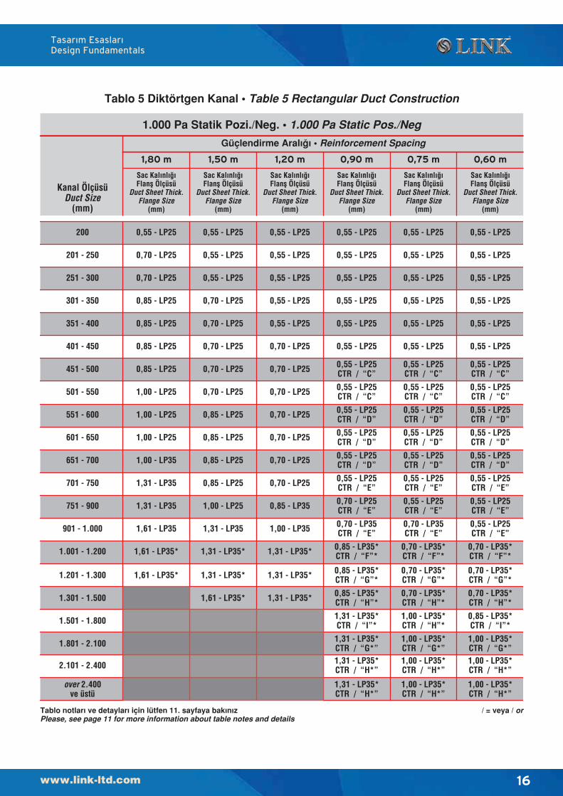
16
Tablo notlar› ve detaylar› için lütfen 11. sayfaya bak›n›zPlease, see page 11 for more information about table notes and details
Tablo 5 Diktörtgen Kanal • Table 5 Rectangular Duct Construction
Sac Kal›nl›¤›Flanfl Ölçüsü
Duct Sheet Thick.Flange Size
(mm)
Güçlendirme Aral›¤› • Reinforcement Spacing
1.000 Pa Statik Pozi./Neg. • 1.000 Pa Static Pos./Neg
1,50 m 1,20 m 0,90 m 0,75 m 0,60 m
Sac Kal›nl›¤›Flanfl Ölçüsü
Duct Sheet Thick.Flange Size
(mm)
Sac Kal›nl›¤›Flanfl Ölçüsü
Duct Sheet Thick.Flange Size
(mm)
Sac Kal›nl›¤›Flanfl Ölçüsü
Duct Sheet Thick.Flange Size
(mm)
Sac Kal›nl›¤›Flanfl Ölçüsü
Duct Sheet Thick.Flange Size
(mm)
Sac Kal›nl›¤›Flanfl Ölçüsü
Duct Sheet Thick.Flange Size
(mm)
1,80 m
Kanal ÖlçüsüDuct Size
(mm)
200
251 - 300
301 - 350
351 - 400
401 - 450
451 - 500
501 - 550
551 - 600
601 - 650
651 - 700
701 - 750
751 - 900
901 - 1.000
1.001 - 1.200
2.101 - 2.400
1.301 - 1.500
1.501 - 1.800
1.801 - 2.100
1.201 - 1.300
201 - 250
over 2.400ve üstü
1,61 - LP35* 1,31 - LP35*
/ = veya / or
Tasar›m Esaslar›Design Fundamentals
17
Sac Kal›nl›¤›Flanfl Ölçüsü
Duct Sheet Thick.Flange Size
(mm)
Sac Kal›nl›¤›Flanfl Ölçüsü
Duct Sheet Thick.Flange Size
(mm)
Sac Kal›nl›¤›Flanfl Ölçüsü
Duct Sheet Thick.Flange Size
(mm)
Sac Kal›nl›¤›Flanfl Ölçüsü
Duct Sheet Thick.Flange Size
(mm)
Sac Kal›nl›¤›Flanfl Ölçüsü
Duct Sheet Thick.Flange Size
(mm)
Sac Kal›nl›¤›Flanfl Ölçüsü
Duct Sheet Thick.Flange Size
(mm)
200
251 - 300
301 - 350
351 - 400
401 - 450
451 - 500
501 - 550
551 - 600
601 - 650
651 - 700
701 - 750
751 - 900
901 - 1.000
1.001 - 1.200
2.101 - 2.400
1.301 - 1.500
1.501 - 1.800
1.801 - 2.100
1.201 - 1.300
201 - 250
over 2.400ve üstü
0,70 - LP25
0,70 - LP25
0,85 - LP25
1,00 - LP25
1,00 - LP25
1,00 - LP25
1,00 - LP25
1,00 - LP25
1,00 - LP35
0,55 - LP25CTR / “B”
0,55 - LP25CTR / “C”
0,55 - LP25CTR / “C”
0,55 - LP25CTR / “E”
0,85 - LP25
1,31 - LP35
1,31 - LP35
1,31 - LP35
0,70 - LP25CTR / “E”
0,70 - LP25CTR / “E”
0,85 - LP35CTR / “F”
0,85 - LP35*CTR / “F”
1,31 - LP35*CTR / “J”*
1,31 - LP35
0,85 - LP25
0,85 - LP25
0,85 - LP35
1,00 - LP35
1,00 - LP35
1,31 - LP35
0,55 - LP25CTR / “C”
0,55 - LP25CTR / “C”
0,55 - LP25CTR / “C”
0,70 - LP25CTR / “D”
0,70 - LP25CTR / “D”
0,70 - LP25CTR / “E”
0,70 - LP25CTR / “E”
0,85 - LP35CTR / “F”
1,00 - LP35*CTR / “F”*
1,00 - LP35*CTR / “G”*
1,31 - LP35*CTR / “I”*
0,70 - LP25CTR / “F”
1,31 - LP35*CTR / “I”*
0,55 - LP25CTR / “C”
0,55 - LP25CTR / “D”
0,55 - LP25CTR / “D”
0,70 - LP25CTR / “E”
0,70 - LP25CTR / “F”
0,85 - LP35*CTR / “G”*
1,00 - LP35*CTR / “I”*
1,00 - LP35*CTR / “I”*
0,55 - LP25
0,70 - LP25
0,70 - LP25
0,85 - LP25
0,85 - LP25
0,55 - LP25CTR / “B”
0,55 - LP25CTR / “C”
0,55 - LP25CTR / “C”
0,55 - LP25CTR / “C”
0,55 - LP25CTR / “C”
0,55 - LP25
0,70 - LP25
0,70 - LP25
0,70 - LP25
0,70 - LP25
0,70 - LP25
1,00 - LP35
0,70 - LP25
0,70 - LP25
0,85 - LP25
0,85 - LP25
0,85 - LP35
0,85 - LP35
1,61 - LP35
1,61 - LP35* 1,61 - LP35*
1,61 - LP35*
1,31 - LP35*
1,31 - LP35*
1,61 - LP35*
1,61 - LP35*
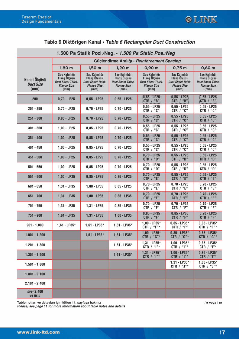
Tablo notlar› ve detaylar› için lütfen 11. sayfaya bak›n›zPlease, see page 11 for more information about table notes and details
Tablo 6 Diktörtgen Kanal • Table 6 Rectangular Duct Construction
Güçlendirme Aral›¤› • Reinforcement Spacing
1.500 Pa Statik Pozi./Neg. • 1.500 Pa Static Pos./Neg
1,50 m 1,20 m 0,90 m 0,75 m 0,60 m1,80 m
Kanal ÖlçüsüDuct Size
(mm)
0,70 - LP25CTR / “F”
0,85 - LP35*CTR / “F”*
0,85 - LP35*CTR / “G”*
0,85 - LP35*CTR / “I”*
0,85 - LP35*CTR / “I”*
0,55 - LP25CTR / “B”
0,55 - LP25CTR / “C”
0,55 - LP25CTR / “C”
0,55 - LP25CTR / “C”
0,55 - LP25CTR / “C”
0,55 - LP25CTR / “E”
0,70 - LP25CTR / “E”
0,55 - LP25CTR / “C”
0,55 - LP25CTR / “D”
0,55 - LP25CTR / “D”
0,70 - LP25CTR / “E”
0,70 - LP25CTR / “F”
1,00 - LP35*CTR / “J”*
/ = veya / or
1,31 - LP25
1,31 - LP35
1,31 - LP35
1,31 - LP35
1,61 - LP35
1,61 - LP35
1,61 - LP35
0,85 - LP35*“I”*
1,00 - LP25
1,00 - LP25
1,00 - LP25
1,00 - LP25
1,31 - LP25
1,31 - LP35
1,31 - LP35
1,31 - LP35
1,31 - LP35
1,31 - LP35
1,31 - LP35
0,55 - LP25“C”
0,55 - LP25“C”
0,55 - LP25“C”
0,70 - LP25“C”
0,70 - LP25“D”
0,70 - LP25“D”
0,85 - LP25“E”
0,85 - LP25“E”
0,85 - LP35“F”
0,85 - LP35“F”
0,85 - LP35“F”
0,85 - LP35“G”
1,00 - LP35*“H”*
1,31 - LP35*“I”*
1,31 - LP35*“I”*
1,31 - LP35*“I”*
0,55 - LP25“C”
0,55 - LP25“C”
0,55 - LP25“C”
0,55 - LP25“C”
0,70 - LP25“D”
0,70 - LP25 “D”
0,70 - LP25“E”
0,70 - LP25“E”
0,70 - LP25“F”
0,70 - LP25“F”
0,70 - LP35“F”
0,70 - LP35“G”
0,85 - LP35*“H”*
1,00 - LP35*“I”*
1,31 - LP35*“I”*
1,31 - LP35*“I”*
0,70 - LP35*“H”*
0,85 - LP35*“I”*
0,85 - LP35*“I”*
1,31 - LP25
1,00 - LP25
1,00 - LP25
1,00 - LP25
1,00 - LP25
1,00 - LP25
1,00 - LP25
1,00 - LP25
1,00 - LP25
1,00 - LP25
1,00 - LP25
1,00 - LP25
1,31 - LP25
1,31 - LP35
1,31 - LP35
1,31 - LP35
1,31 - LP35
1,31 - LP35
0,55 - LP25“C”
0,55 - LP25“C”
0,55 - LP25“C”
0,55 - LP25“C”
0,55 - LP25“D”
0,55 - LP25“D”
0,70 - LP25“E”
0,70 - LP25“E”
0,70 - LP25“F”
0,70 - LP25“F”
0,70 - LP25“F”
0,70 - LP35“G”
1,00 - LP35*“J”*
1,61 - LP35*
1,61 - LP35*
1,31 - LP35*
1,31 - LP35*
1,61 - LP35*
Sac Kal›nl›¤›Flanfl Ölçüsü
Duct Sheet Thick.Flange Size
(mm)
Sac Kal›nl›¤›Flanfl Ölçüsü
Duct Sheet Thick.Flange Size
(mm)
Sac Kal›nl›¤›Flanfl Ölçüsü
Duct Sheet Thick.Flange Size
(mm)
Sac Kal›nl›¤›Flanfl Ölçüsü
Duct Sheet Thick.Flange Size
(mm)
Sac Kal›nl›¤›Flanfl Ölçüsü
Duct Sheet Thick.Flange Size
(mm)
Sac Kal›nl›¤›Flanfl Ölçüsü
Duct Sheet Thick.Flange Size
(mm)
200
251 - 300
301 - 350
351 - 400
401 - 450
451 - 500
501 - 550
551 - 600
601 - 650
651 - 700
701 - 750
751 - 900
901 - 1.000
1.001 - 1.200
2.101 - 2.400
1.301 - 1.500
1.501 - 1.800
1.801 - 2.100
1.201 - 1.300
201 - 250
over 2.400ve üstü
Tasar›m Esaslar›Design Fundamentals
18
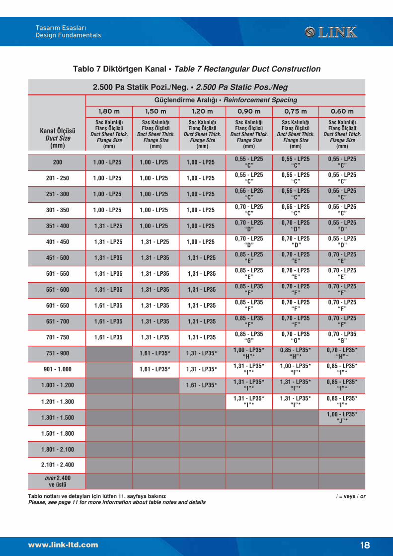
Tablo notlar› ve detaylar› için lütfen 11. sayfaya bak›n›zPlease, see page 11 for more information about table notes and details
Tablo 7 Diktörtgen Kanal • Table 7 Rectangular Duct Construction
Güçlendirme Aral›¤› • Reinforcement Spacing
2.500 Pa Statik Pozi./Neg. • 2.500 Pa Static Pos./Neg
1,50 m 1,20 m 0,90 m 0,75 m 0,60 m1,80 m
Kanal ÖlçüsüDuct Size
(mm)
0,85 - LP35*“I”*
1,00 - LP35*“H”*
1,31 - LP35*“I”*
1,31 - LP35*“I”*
1,31 - LP35*“I”*
0,85 - LP35*“H”*
1,00 - LP35*“I”*
1,31 - LP35*“I”*
1,31 - LP35*“I”*
0,70 - LP35*“H”*
0,85 - LP35*“I”*
0,85 - LP35*“I”*
1,00 - LP35*“J”*
1,61 - LP35*
1,61 - LP35*
1,31 - LP35*
1,31 - LP35*
1,61 - LP35*
/ = veya / or
19
Tasar›m Esaslar›Design Fundamentals
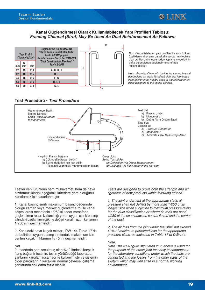
Testler yeni ürünlerin hem mukavemet, hem de havasızdırmazlıklarını afla¤ıdaki kriterlere göre oldu¤unukanıtlamak için tasarlanmıfltır:
1. Kanal basınç sınıfı maksimum basınç de¤erindeoldu¤u zaman veya merkez güçlendirme rot ile kanalköflesi arası mesafenin 1/250’si kadar mesafedegüçlendirme rotları kullanıldı¤ı yerde uygun statik basınçaltındaki ba¤lantının çökme de¤eri kanalın uzun kenarının1/250’sini geçmemelidir.
2. Kanaldaki hava kaçak miktarı, DW 144 Tablo 17’dede belirtilen uygun basınç sınıfındaki maksimum izinverilen kaçak miktarının % 40’ını geçmemelidir.
Not2. maddede flart koflulmufl olan %40 ifadesi, karflılıkflanfl ba¤lantı testinin, testin yürütüldü¤ü laboratuarflartlarını karflılaması amac› ile kullanılmıfltır ve sistemindi¤er parçalarının kaçakları normal çevresel çalıflmaflartlarında çok daha fazla olabilir.
Kanal Güçlendirmesi Olarak Kullan›labilecek Yap› Profilleri Tablosu:Framing Channel (Strut) May Be Used As Duct Reinforcement As Follows:
Test Prosedürü • Test Procedure
Karflılıklı Flanfllı Ba¤lantı(a) Çökme (Do¤rudan ölçüm)(b) Sızıntı de¤erleri için test edilir.
(Test seti üzerindeki manometreden ölçüm)
Cross JointBeing Tested For:
(a) Deflection (via Direct Measurement)(b) Leakage (via Flow meter in the test set)
GüçlendiricilerStiffeners
Manometreye StatikBas›nç DönüflüStatic Pressure returnto manometer
Test Setia) Bas›nç Üreticib) Manometrec) Do¤ru Ak›m Ölçüm Saati
Test Set:Consist of:
a) Pressure Genaratorb) Manometerc) Accurate Flow Measuring Meter
Tests are designed to prove both the strength and airtightness of new products within following criteria:
1. The joint under test at the appropriate static airpressure shall not deflect by more than 1/250 of itslongest side when subjected to maximum pressure ratingfor the duct classification or where tie rods are used1/250 of the span between central tie rod and the cornerof the duct.
2. The air loss from the joint under test shall not exceed40% of maximum permitted loss for the appropriatepressure class, as indicated in Table 17 of DW/144.
NoteNote The 40% figure stipulated in 2. above is used forthe purpose of the cross joint test only to compensatefor the laboratory conditions under which the tests areconducted and the losses from the other parts of thesystem which may well arise in a normal workingenvironment.
Not: Yanda listelenen yapı profilleri ile aynı fizikselözelliklere sahip, ama daha kalın sacdan imal edilmiflolan profiller daha ince sacdan yapılmıfl modellerininatıfta bulunuldu¤u güçlendirme sınıfındakullanılabilirler.
Note : Framing Channels having the same physicaldimensions as those listed left side, but fabricatedfrom thicker steel maybe used at the reinforcementclass assigned to the lighter version.
W
H
t
Yap› ProfiliChannel (Strut)
Güçlendirme S›n›f› SMACNA“Hava Kanal› ‹malat Standart›”
Tablo 2-29M’ye göreReinforcement Class Per SMACNA
“Duct Construction Standards”Table 2-29M
A, B, C, DD, EF, G
H, I, JK, L
2222456060
Hmm
4545454570
Wmm
2,02,52,52,53,0
tmm
20
Tasar›m Esaslar›Design Fundamentals
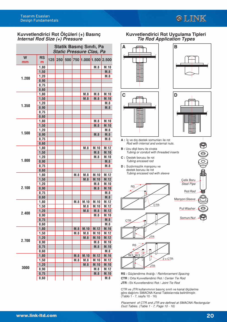
Kuvvetlendirici Rot Ölçüleri (+) Bas›nçInternal Rod Size (+) Pressure
Statik Bas›nç S›n›f›, PaStatic Pressure Clas, Pa
Wmm
RSm 125 250 500 750 1.000 1.500 2.500
1.200
1,801,501,200,900,750,601,801,501,200,900,750,601,801,501,200,900,750,601,801,501,200,900,750,601,801,501,200,900,750,601,801,501,200,900,750,601,801,501,200,900,750,601,801,501,200,900,750,60
1.350
1.500
1.800
2.100
2.400
2.700
3000
M.8
M.8
M.8M.8
M.8M.8
M.8M.8
M.8
M.8M.8
M.10M.8M.8
M.10M.8M.8
M.10M.8M.8
M.8
M.8M.8
M.8M.8
M.8
M.10M.8M.8
M.10M.10M.8M.8
M.10M.10M.8M.8
M.12M.10M.10M.8M.8
M.12M.10M.10M.8M.8
M.10M.8M.8
M.10M.10M.8M.8
M.10M.10M.8M.8M.8
M.12M.10M.10M.8M.8
M.12M.12M.10M.10M.8M.8M.12M.12M.12M.10M.8M.8M.16M.12M.12M.10M.10M.8M.16M.12M.10M.12M.10M.8
RS : Güçlendirme Aral›¤› / Reinforcement Spacing
CTR : Orta Kuvvetlendirici Rot / Center Tie Rod
JTR : Ek Kuvvetlendirici Rot / Joint Tie Rod
CTR ve JTR kullan›m›n›n bas›nç s›n›f› ve kanal ölçülerinegöre da¤›l›m› SMACNA Kanal Tablolar›nda belirtilmifltir.(Tablo 1 - 7, sayfa 10 - 16)
Placement of CTR and JTR are defined at SMACNA RectangularDuct Tables. (Table 1 - 7, Page 10 - 16)
RS
CTR
CTR
JTR
2 x CTR
JTR
RS
W/3 W/3
Kuvvetlendirici Rot Uygulama TipleriTie Rod Application Types
A : ‹ç ve d›fl destek somunlar› ile rotRod with internal and external nuts.
B : Ucu diflli boru ile civataTubing or conduit with threaded inserts
C : Destek borusu ile rotTubing encased rod
D : S›zd›rmazl›k manflonu vedestek borusu ile rotTubing encased rod with sleeve
BA
DC
Pul/Washer
Somun/Nut
Manflon/Sleeve
Çelik BoruSteel Pipe
Rot/Rod
21
tasar›m esaslar›design fundamentals
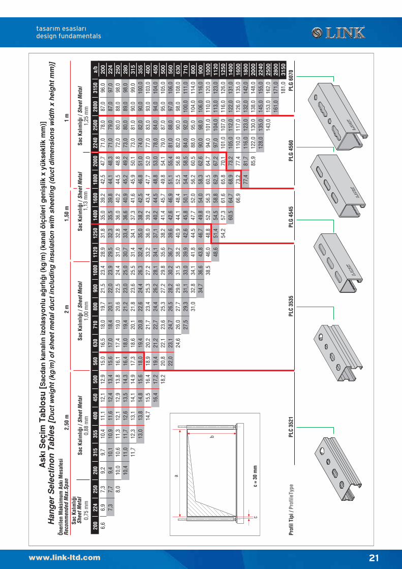
Ask
› Seç
im T
ablo
su [
Sac
dan
kan
al›n
izo
lasy
on
lu a
¤›r
l›¤› (
kg/m
) (k
anal
ölç
üle
ri g
enifl
lik x
yü
ksek
lik m
m)]
Han
ger
Sel
ecti
no
n T
able
s [D
uct
wei
gh
t (k
g/m
) o
f sh
eet
met
al d
uct
incl
ud
ing
insu
lati
on
wit
h s
hee
tin
g (
du
ct d
imen
sio
ns
wid
th x
hei
gh
t m
m)]
200
6,6
224
6,9
7,3
250
7,3
7,7
8,0
280
9,2
9,4
10,0
10,4
315
9,7
10,1
10,6
11,0
11,7
355
10,4
10,9
11,3
11,7
12,3
13,0
400
11,1
11,6
12,1
12,6
13,1
13,8
14,7
450
12,1
12,4
12,9
13,5
14,1
14,8
15,5
16,4
500
12,9
13,4
13,8
14,3
14,9
15,6
16,4
17,2
18,2
560
15,0
15,6
16,1
16,4
17,3
18,0
18,9
19,4
20,8
22,0
630
16,5
17,0
17,4
18,0
18,6
19,4
20,2
21,2
22,1
23,1
24,6
710
18,0
18,4
19,0
19,4
20,1
20,8
21,7
22,7
23,6
24,7
26,0
27,5
800
19,7
20,1
20,6
21,2
21,8
22,6
23,4
24,4
25,3
26,5
27,7
29,3
31,0
900
21,5
22,0
22,5
23,0
23,6
24,4
25,3
26,2
27,2
28,2
29,6
31,1
32,8
34,7
1000
23,4
23,9
24,4
25,0
25,5
26,3
27,2
28,1
29,8
30,2
31,5
33,0
34,1
36,6
38,5
1120
28,9
29,5
31,0
30,7
31,4
32,4
33,2
34,1
35,6
36,7
38,2
39,9
41,8
43,8
46,0
48,6
1250
31,8
32,3
32,8
33,4
34,1
35,0
36,0
37,1
38,2
39,6
40,9
42,6
44,5
46,7
48,8
51,4
54,2
1400
35,0
35,5
36,0
36,6
37,3
38,2
39,2
40,2
41,4
42,6
44,1
45,8
47,7
49,8
52,0
54,5
57,3
60,5
1600
39,2
39,8
40,2
40,9
41,6
42,5
43,4
44,5
45,7
46,9
48,4
50,1
52,0
54,0
56,3
58,8
61,6
64,7
66,9
1800
42,5
44,1
44,5
45,2
45,9
46,8
47,7
48,8
49,8
51,1
52,5
54,4
56,2
58,3
60,5
62,9
65,8
68,9
73,2
77,4
2000
47,7
48,3
48,8
49,2
50,1
51,0
52,0
53,0
54,1
55,4
56,8
58,5
60,5
62,6
64,7
67,2
70,1
73,2
77,4
81,7
85,9
2240
71,0
71,0
72,0
73,0
73,0
74,0
77,0
78,0
79,0
81,0
82,0
84,0
88,0
90,0
94,0
97,0
101,
010
5,0
110,
011
6,0
122,
012
8,0
2500
78,0
79,0
80,0
80,0
81,0
82,0
83,0
84,0
87,0
88,0
90,0
92,0
95,0
98,0
101,
010
4,0
107,
011
2,0
117,
012
3,0
130,
013
5,0
143,
0
2800
87,0
87,0
88,0
89,0
90,0
90,0
93,0
94,0
95,0
97,0
98,0
100,
010
4,0
106,
011
0,0
113,
011
6,0
122,
012
6,0
132,
013
8,0
145,
015
3,0
161,
0
3150
96,0
97,0
98,0
98,0
99,0
100,
010
3,0
104,
010
5,0
106,
010
8,0
111,
011
4,0
116,
012
0,0
123,
012
6,0
131,
013
5,0
142,
014
8,0
155,
016
2,0
171,
018
1,0
0,75
mm
Sac
Kal›n
l›¤›
Shee
t Met
alSa
c Ka
l›nl›¤
› / S
heet
Met
al0,
88 m
mSa
c Ka
l›nl›¤
› / S
heet
Met
al 1
,13
mm
PLC
3521
PLC
3535
PLG
454
5
2,50
m2
mÖ
neri
len
Mak
sim
um A
sk› M
esaf
esi
Reco
mm
ende
d M
ax.S
pan
Prof
il Ti
pi /
Prof
ileTy
pe
c
a
b
1,50
m1
m
PLG
456
0PL
G 6
070a/
b20
022
425
028
031
535
540
045
050
056
063
071
080
090
010
0011
2012
5014
0016
0018
0020
0022
4025
0028
0031
50
Sac
Kal›n
l›¤› /
She
et M
etal
1,25
mm
c =
30 m
m
Sac
Kal›n
l›¤› /
She
et M
etal
1,00
mm
22
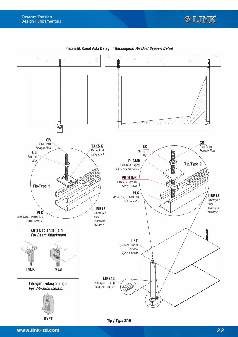
Prizmatik Kanal Ask› Detay› / Rectangular Air Duct Support Detail
Tip / Type SDH
LSTÇekmeli Dübel
ScrewType Anchor
CSSomun
Nut
PLGMKKare Kilit Kapa¤›
Easy Lock Nut Cover
PROLINKTAKS-G Somun
TAKS-G Nut
PLG45x45x2,5 PROLINK
Profil /Profile
CRAsk› RotuHanger Rod
LIRB13VibrasyonAl›c›VibrationIsolator
LIRB12‹zolasyon Lasti¤iIsolation Rubber
INUK MLB
Kirifl Ba¤lant›s› içinFor Beam Attachment
HYET
Titreflim ‹zolasyonu içinFor Vibration Isolator
CSSomun
Nut
CRAsk› Rotu
Hanger Rod
PLC35x35x0,9 PROLINK
Profil /Profile
TAKS CKolay KilitEasy Lock
Tip/Type-1
Tip/Type-2
Tip / Type SDV
Tasar›m Esaslar›Design Fundamentals
LIRB13VibrasyonAl›c›VibrationIsolator
23
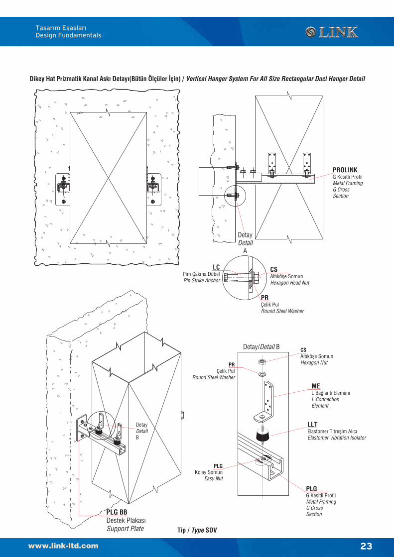
Dikey Hat Prizmatik Kanal Ask› Detay›(Bütün Ölçüler ‹çin) / Vertical Hanger System For All Size Rectangular Duct Hanger Detail
PLG BBDestek Plakas›Support Plate
CSAlt›köfle SomunHexagon Head Nut
LCPim Çakma DübelPin Strike Anchor
PRÇelik PulRound Steel Washer
DetayDetail
A
PROLINKG Kesitli ProfilMetal FramingG CrossSection
DetayDetailB
Tip / Type SDV
MEL Ba¤lant› Eleman›L ConnectionElement
CSAlt›köfle SomunHexagon NutPR
Çelik PulRound Steel Washer
Detay/Detail B
PLGG Kesitli ProfilMetal FramingG CrossSection
PLGKolay Somun
Easy Nut
LLTElastomer Titreflim Al›c›Elastomer Vibration Isolator
Tasar›m Esaslar›Design Fundamentals
24
Bu sayfa bilinçli olarak bofl b›rak›lm›flt›r.This pages intentionally left blank
25
Hava Kanal› Ba¤lant› SistemleriAir Duct Connection System
ürünlerproducts
26
Hava Kanal› Ba¤lant› SistemleriAir Duct Connection System
Bu sayfa bilinçli olarak bofl b›rak›lm›flt›r.This pages intentionally left blank
27
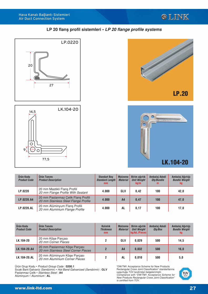
LP 20 flanfl profil sistemleri • LP 20 flange profile systems
LP.20
LK.104-20
LP.0220
LK.104-2014,5
9
77,5
Hava Kanal› Ba¤lant› SistemleriAir Duct Connection System
Ürün KoduProduct Code
Ürün Tan›m›Product Description
Standart BoyStandard Length
mm
MalzemeMaterial
Birim a¤›rl›kUnit Weight
kg/m
Ambalaj AdediQty/Bundle
m
Ambalaj A¤›rl›¤›Bundle Weight
kg
LP.0220
LP.0220.A4
LP.0220.AL
20 mm Mastikli Flanfl Profili20 mm Flange Profile With Sealant
20 mm Paslanmaz Çelik Flanfl Profili20 mm Stainless Steel Flange Profile
20 mm Alüminyum Flanfl Profili20 mm Aluminium Flange Profile
4.000
4.000
4.000
GLV
A4
AL
0,42
0,47
0,17
100
100
100
42,0
47,0
17,0
Ürün Grup Kodu • Product Group Code : 0200.1S›cak Bant Galvaniz (Sendzimir) • Hot Band Galvanized (Sendzimir) : GLVPaslanmaz Çelik • Stainless Steel : A4Alüminyum • Aluminium : AL
20 mm Köfle Parças›20 mm Corner Pieces
20 mm Paslanmaz Köfle Parças›20 mm Stainless Steel Corner Pieces
20 mm Alüminyum Köfle Parças›20 mm Aluminium Corner Pieces
2
2
2
GLV
A4
AL
0,029
0,032
0,010
500
500
500
14,5
16,0
5,0
LK.104-20
LK.104-20.A4
LK.104-20.AL
Ürün KoduProduct Code
Ürün Tan›m›Product Description
Kal›nl›kThickness
mm
MalzemeMaterial
Birim a¤›rl›kUnit Weight
kg/Ad./Pieces
Ambalaj AdediQty/Box
Ambalaj A¤›rl›¤›Bundle Weight
kg
27
20
“DW/TM1 Acceptance Scheme for New ProductsRectangular Cross Joint Classification” standartlar›nauygunlu¤u TÜV taraf›ndan belgelenmifltir.Compliance with “DW/TM1 Acceptance Scheme forNew Products Rectangular Cross Joint Classification”is certified from TÜV.
28
LP.30
LK.104-30
LP.0230
LK.104-30
101,5
24,4
12,5
Hava Kanal› Ba¤lant› SistemleriAir Duct Connection System
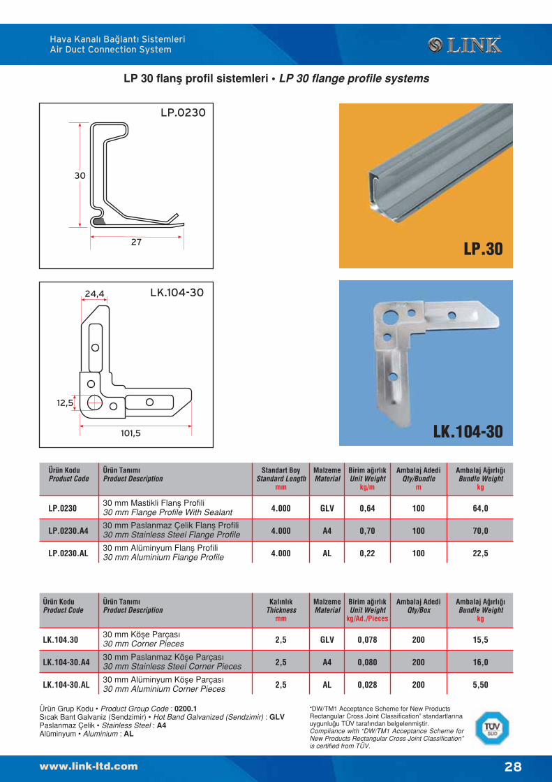
LP 30 flanfl profil sistemleri • LP 30 flange profile systems
Ürün KoduProduct Code
Ürün Tan›m›Product Description
Standart BoyStandard Length
mm
MalzemeMaterial
Birim a¤›rl›kUnit Weight
kg/m
Ambalaj AdediQty/Bundle
m
Ambalaj A¤›rl›¤›Bundle Weight
kg
LP.0230
LP.0230.A4
LP.0230.AL
30 mm Mastikli Flanfl Profili30 mm Flange Profile With Sealant
30 mm Paslanmaz Çelik Flanfl Profili30 mm Stainless Steel Flange Profile
30 mm Alüminyum Flanfl Profili30 mm Aluminium Flange Profile
4.000
4.000
4.000
GLV
A4
AL
0,64
0,70
0,22
100
100
100
64,0
70,0
22,5
Ürün Grup Kodu • Product Group Code : 0200.1S›cak Bant Galvaniz (Sendzimir) • Hot Band Galvanized (Sendzimir) : GLVPaslanmaz Çelik • Stainless Steel : A4Alüminyum • Aluminium : AL
30 mm Köfle Parças›30 mm Corner Pieces
30 mm Paslanmaz Köfle Parças›30 mm Stainless Steel Corner Pieces
30 mm Alüminyum Köfle Parças›30 mm Aluminium Corner Pieces
2,5
2,5
2,5
GLV
A4
AL
0,078
0,080
0,028
200
200
200
15,5
16,0
5,50
LK.104.30
LK.104-30.A4
LK.104-30.AL
Ürün KoduProduct Code
Ürün Tan›m›Product Description
Kal›nl›kThickness
mm
MalzemeMaterial
Birim a¤›rl›kUnit Weight
kg/Ad./Pieces
Ambalaj AdediQty/Box
Ambalaj A¤›rl›¤›Bundle Weight
kg
30
27
“DW/TM1 Acceptance Scheme for New ProductsRectangular Cross Joint Classification” standartlar›nauygunlu¤u TÜV taraf›ndan belgelenmifltir.Compliance with “DW/TM1 Acceptance Scheme forNew Products Rectangular Cross Joint Classification”is certified from TÜV.
29
LP.40
LK.104-40
LP.0240
40
25
LK.104-40
120
34
13 x 21
Hava Kanal› Ba¤lant› SistemleriAir Duct Connection System
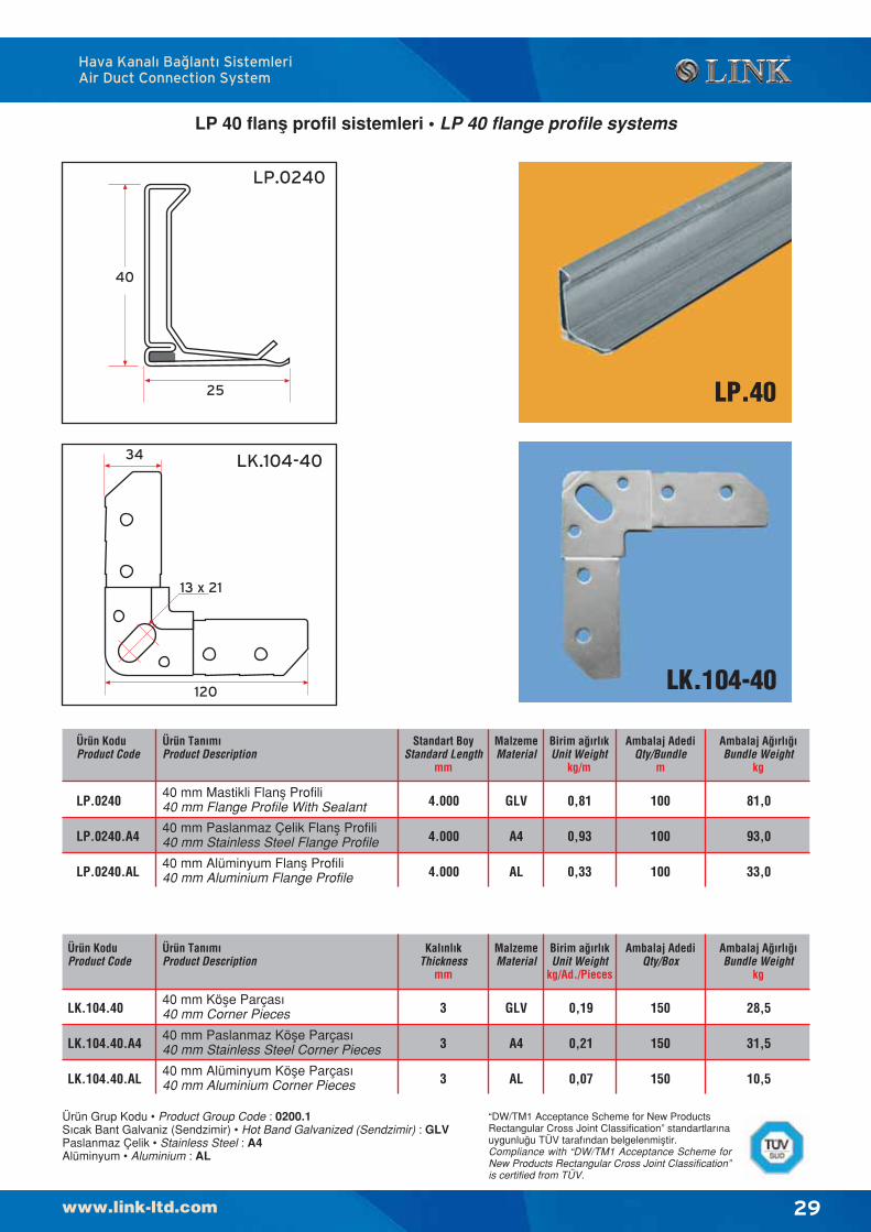
LP 40 flanfl profil sistemleri • LP 40 flange profile systems
Ürün KoduProduct Code
Ürün Tan›m›Product Description
Standart BoyStandard Length
mm
MalzemeMaterial
Birim a¤›rl›kUnit Weight
kg/m
Ambalaj AdediQty/Bundle
m
Ambalaj A¤›rl›¤›Bundle Weight
kg
LP.0240
LP.0240.A4
LP.0240.AL
40 mm Mastikli Flanfl Profili40 mm Flange Profile With Sealant
40 mm Paslanmaz Çelik Flanfl Profili40 mm Stainless Steel Flange Profile
40 mm Alüminyum Flanfl Profili40 mm Aluminium Flange Profile
4.000
4.000
4.000
GLV
A4
AL
0,81
0,93
0,33
100
100
100
81,0
93,0
33,0
Ürün Grup Kodu • Product Group Code : 0200.1S›cak Bant Galvaniz (Sendzimir) • Hot Band Galvanized (Sendzimir) : GLVPaslanmaz Çelik • Stainless Steel : A4Alüminyum • Aluminium : AL
40 mm Köfle Parças›40 mm Corner Pieces
40 mm Paslanmaz Köfle Parças›40 mm Stainless Steel Corner Pieces
40 mm Alüminyum Köfle Parças›40 mm Aluminium Corner Pieces
3
3
3
GLV
A4
AL
0,19
0,21
0,07
150
150
150
28,5
31,5
10,5
LK.104.40
LK.104.40.A4
LK.104.40.AL
Ürün KoduProduct Code
Ürün Tan›m›Product Description
Kal›nl›kThickness
mm
MalzemeMaterial
Birim a¤›rl›kUnit Weight
kg/Ad./Pieces
Ambalaj AdediQty/Box
Ambalaj A¤›rl›¤›Bundle Weight
kg
“DW/TM1 Acceptance Scheme for New ProductsRectangular Cross Joint Classification” standartlar›nauygunlu¤u TÜV taraf›ndan belgelenmifltir.Compliance with “DW/TM1 Acceptance Scheme forNew Products Rectangular Cross Joint Classification”is certified from TÜV.
30
LP.0225
LK.104-25
25
25
81
20
9
LK.204-25
82,4
20
9
LK.104-25
LK.204-25
LP.25
Hava Kanal› Ba¤lant› SistemleriAir Duct Connection System
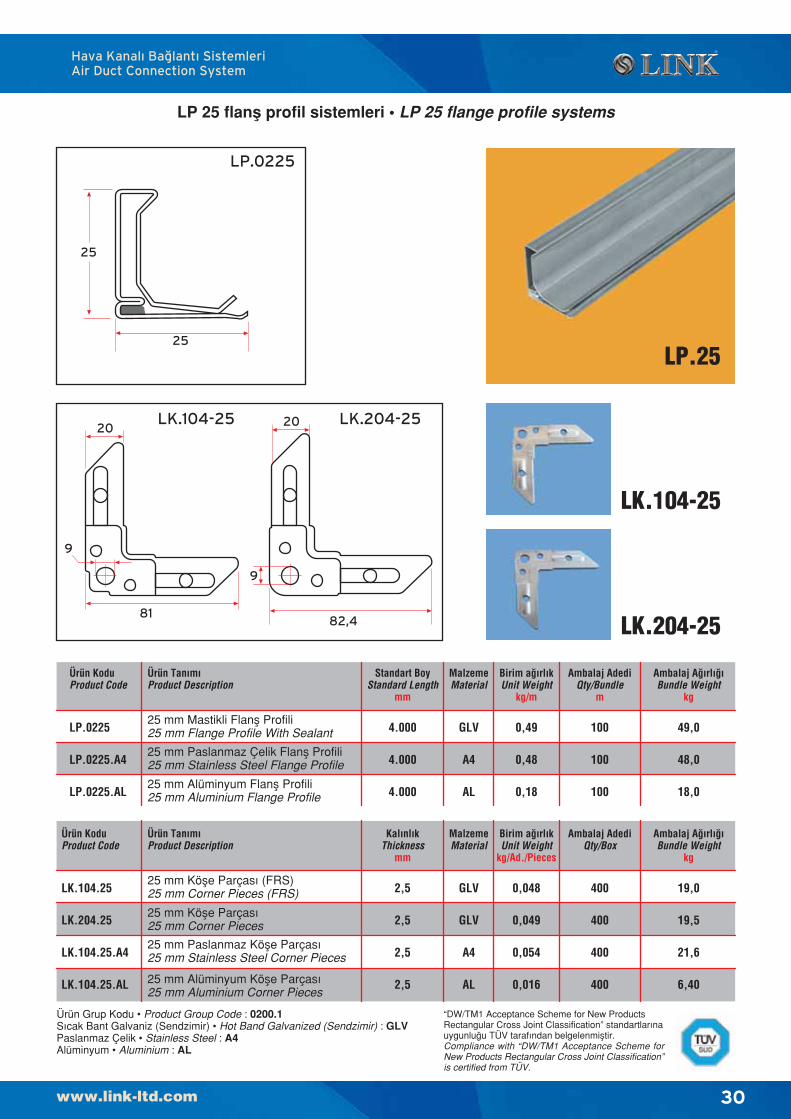
LP 25 flanfl profil sistemleri • LP 25 flange profile systems
Ürün KoduProduct Code
Ürün Tan›m›Product Description
Standart BoyStandard Length
mm
MalzemeMaterial
Birim a¤›rl›kUnit Weight
kg/m
Ambalaj AdediQty/Bundle
m
Ambalaj A¤›rl›¤›Bundle Weight
kg
LP.0225
LP.0225.A4
LP.0225.AL
25 mm Mastikli Flanfl Profili25 mm Flange Profile With Sealant
25 mm Paslanmaz Çelik Flanfl Profili25 mm Stainless Steel Flange Profile
25 mm Alüminyum Flanfl Profili25 mm Aluminium Flange Profile
4.000
4.000
4.000
GLV
A4
AL
0,49
0,48
0,18
100
100
100
49,0
48,0
18,0
Ürün Grup Kodu • Product Group Code : 0200.1S›cak Bant Galvaniz (Sendzimir) • Hot Band Galvanized (Sendzimir) : GLVPaslanmaz Çelik • Stainless Steel : A4Alüminyum • Aluminium : AL
25 mm Köfle Parças› (FRS)25 mm Corner Pieces (FRS)
25 mm Köfle Parças›25 mm Corner Pieces
25 mm Alüminyum Köfle Parças›25 mm Aluminium Corner Pieces
2,5
2,5
2,5
2,5
GLV
GLV
A4
AL
0,048
0,049
0,054
0,016
400
400
400
400
19,0
19,5
21,6
6,40
LK.104.25
LK.204.25
LK.104.25.A4
LK.104.25.AL
25 mm Paslanmaz Köfle Parças›25 mm Stainless Steel Corner Pieces
Ürün KoduProduct Code
Ürün Tan›m›Product Description
Kal›nl›kThickness
mm
MalzemeMaterial
Birim a¤›rl›kUnit Weight
kg/Ad./Pieces
Ambalaj AdediQty/Box
Ambalaj A¤›rl›¤›Bundle Weight
kg
“DW/TM1 Acceptance Scheme for New ProductsRectangular Cross Joint Classification” standartlar›nauygunlu¤u TÜV taraf›ndan belgelenmifltir.Compliance with “DW/TM1 Acceptance Scheme forNew Products Rectangular Cross Joint Classification”is certified from TÜV.
31
LP.35
LK.104-35
LK.204-35
LP.0235
LK.104-35
35
25
LK.204-35
110
30
12
110
30
18 x 12
Hava Kanal› Ba¤lant› SistemleriAir Duct Connection System
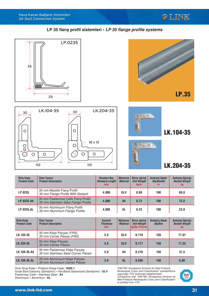
LP 35 flanfl profil sistemleri • LP 35 flange profile systems
Ürün KoduProduct Code
Ürün Tan›m›Product Description
Standart BoyStandard Length
mm
MalzemeMaterial
Birim a¤›rl›kUnit Weight
kg/m
Ambalaj AdediQty/Bundle
m
Ambalaj A¤›rl›¤›Bundle Weight
kg
LP.0235
LP.0235.A4
LP.0235.AL
35 mm Mastikli Flanfl Profili35 mm Flange Profile With Sealant
35 mm Paslanmaz Çelik Flanfl Profili35 mm Stainless Steel Flange Profile
35 mm Alüminyum Flanfl Profili35 mm Aluminium Flange Profile
4.000
4.000
4.000
GLV
A4
AL
0,69
0,72
0,23
100
100
100
69,0
72,0
23,0
Ürün Grup Kodu • Product Group Code : 0200.1S›cak Bant Galvaniz (Sendzimir) • Hot Band Galvanized (Sendzimir) : GLVPaslanmaz Çelik • Stainless Steel : A4Alüminyum • Aluminium : AL
Ürün KoduProduct Code
Ürün Tan›m›Product Description
Kal›nl›kThickness
mm
MalzemeMaterial
Birim a¤›rl›kUnit Weight
kg/Ad./Pieces
Ambalaj AdediQty/Box
Ambalaj A¤›rl›¤›Bundle Weight
kg
35 mm Köfle Parças› (FRS)35 mm Corner Pieces (FRS)
35 mm Köfle Parças›35 mm Corner Pieces
35 mm Alüminyum Köfle Parças›35 mm Aluminium Corner Pieces
3,0
3,0
3,0
3,0
GLV
GLV
A4
AL
0,119
0,117
0,210
0,040
150
150
150
150
17,91
17,53
31,5
6,00
LK.104-35
LK.204-35
LK.104-35.A4
LK.104-35.AL
35 mm Paslanmaz Köfle Parças›35 mm Stainless Steel Corner Pieces
“DW/TM1 Acceptance Scheme for New ProductsRectangular Cross Joint Classification” standartlar›nauygunlu¤u TÜV taraf›ndan belgelenmifltir.Compliance with “DW/TM1 Acceptance Scheme forNew Products Rectangular Cross Joint Classification”is certified from TÜV.
32
LKL.250
LKL.350
LKL.250
M 8x20
23M.8 x 20
30
LKL.350
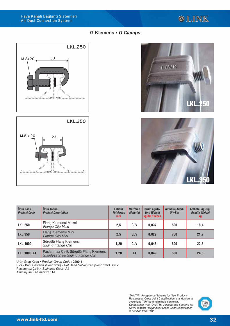
G Klemens • G Clamps
Hava Kanal› Ba¤lant› SistemleriAir Duct Connection System
Ürün Grup Kodu • Product Group Code : 0200.1S›cak Bant Galvaniz (Sendzimir) • Hot Band Galvanized (Sendzimir) : GLVPaslanmaz Çelik • Stainless Steel : A4Alüminyum • Aluminium : AL
Ürün KoduProduct Code
Ürün Tan›m›Product Description
Kal›nl›kThickness
mm
MalzemeMaterial
Birim a¤›rl›kUnit Weight
kg/Ad./Pieces
Ambalaj AdediQty/Box
Ambalaj A¤›rl›¤›Bundle Weight
kg
Flanfl Klemensi MaksiFlange Clip Maxi
Flanfl Klemensi MiniFlange Clip Mini
Paslanmaz Çelik Sürgülü Flanfl KlemensiStainless Steel Sliding Flange Clip
2,5
2,5
1,20
1,20
GLV
GLV
GLV
A4
0,037
0,029
0,045
0,049
500
750
500
500
18,4
21,7
22,5
24,5
LKL.250
LKL.350
LKL.1000
LKL.1000.A4
Sürgülü Flanfl KlemensiSliding Flange Clip
“DW/TM1 Acceptance Scheme for New ProductsRectangular Cross Joint Classification” standartlar›nauygunlu¤u TÜV taraf›ndan belgelenmifltir.Compliance with “DW/TM1 Acceptance Scheme forNew Products Rectangular Cross Joint Classification”is certified from TÜV.
33
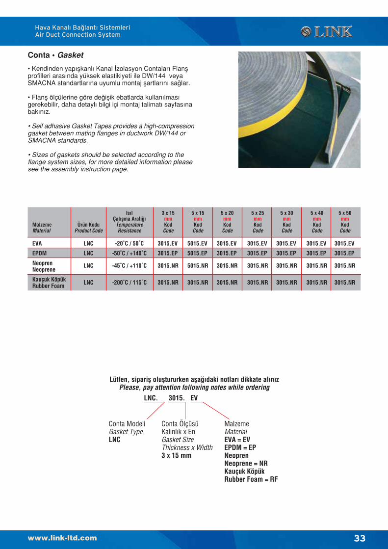
Conta • Gasket
MalzemeMaterial
EVA
EPDM
NeoprenNeoprene
Kauçuk KöpükRubber Foam
Is›lÇal›flma Aral›¤›
TemperatureResistance
3 x 15mmKodCode
3015.EV
3015.EP
3015.NR
5 x 15mmKodCode
5015.EV
5015.EP
5015.NR
5 x 20mmKodCode
3015.EV
3015.EP
3015.NR
5 x 25mmKodCode
3015.EV
3015.EP
3015.NR
5 x 30mmKodCode
3015.EV
3015.EP
3015.NR
5 x 40mmKodCode
3015.EV
3015.EP
3015.NR
5 x 50mmKodCode
3015.EV
3015.EP
3015.NR
-20˚C / 50˚C
-50˚C / +140˚C
-45˚C / +110˚C
LNC
LNC
LNC
Ürün KoduProduct Code
LNC -200˚C / 115˚C 3015.NR 3015.NR 3015.NR 3015.NR 3015.NR 3015.NR 3015.NR
• Kendinden yap›flkanl› Kanal ‹zolasyon Contalar› Flanflprofilleri aras›nda yüksek elastikiyeti ile DW/144 veyaSMACNA standartlar›na uyumlu montaj flartlar›n› sa¤lar.
• Flanfl ölçülerine göre de¤iflik ebatlarda kullan›lmas›gerekebilir, daha detayl› bilgi içi montaj talimat› sayfas›nabak›n›z.
• Self adhasive Gasket Tapes provides a high-compressiongasket between mating flanges in ductwork DW/144 orSMACNA standards.
• Sizes of gaskets should be selected according to theflange system sizes, for more detailed information pleasesee the assembly instruction page.
Lütfen, siparifl olufltururken afla¤›daki notlar› dikkate al›n›zPlease, pay attention following notes while ordering
LNC. 3015. EV
Conta ModeliGasket TypeLNC
Conta ÖlçüsüKal›nl›k x EnGasket SizeThickness x Width3 x 15 mm
MalzemeMaterialEVA = EVEPDM = EPNeoprenNeoprene = NRKauçuk KöpükRubber Foam = RF
Hava Kanal› Ba¤lant› SistemleriAir Duct Connection System

34
Mastik • SealantTan›m›666 Montaj Masti¤i akrilik polimer esasl›, yüzeyekuvvetle yap›flan, elastikiyetini kaybetmeyen, bir fugas›zd›rmazl›k malzemesidir. HVCA - DW/144 – DW/TM1ve Amerikan SMACNA standartlarına uyumludur.
Teknik ÖzelliklerKopma Kuvveti Mpa : ≥0, 2 (DIN 53504)Elastikiyet,% : > 100 (DIN 53504)Sertlik, Shore A : 20-40 (DIN 53505)Yo¤unluk, gr/cm3 : 1.65 ± 0.02Kurumada Hacim Kayb› : 18-20 (DIN 52451)Fugadaki Genleflme Oran› : ort. %10S›cakl›k Dayan›m› : -20°C ila +70°CÇal›flma S›cakl›¤› : +5°C ila +40°CYüzey Kuruma : ort. 1 saatRenkler: Beyaz, GriBilefliminde sa¤l›¤a zararl›, zehirli ve cildi tahrifl eden maddeler bulunmaz.Yafllanmaya ve UV ›fl›nlar›na dayan›kl›d›r.Antibakteriyaldir.
Uygulama• Uygulama yüzeyleri kuru, ya¤s›z ve tozsuz olmal›d›r.• Kartuflun a¤z› fugaya göre kesilip, tabancaya tak›l›r.• 666 Montaj Masti¤i s›k›ld›ktan sonra yüzeyi spatula
veya ›slak sünger ile düzeltilir.• 666 Montaj Masti¤i tatbik edilecek genifllik ve
derinlikler en az 5 mm, maksimum 10 mm olmal›d›r.• Fuga içine malzemeden tasarruf ve uygun tatbikat
fleklini sa¤lamak için PE - fitil veya yumuflak tiphortum yerlefltirilmelidir.
• Yap›flmay› artt›rmak için Primer S veya TS’de kullan›labilir.
Dikkat Edilecek Hususlar• Ya¤›fll› havada d›fl mekanlarda uygulama yap›lmaz.• Uygulama s›ras›nda 666 Montaj Masti¤i bulaflan yerler
ve kullan›lan aletler, malzeme kurumadan su ile temizlenir.• Uygulama ortam›nda s›cakl›¤›n yükselmesi (maks. 80°C)
ve hava neminin düflmesi reaksiyonu h›zland›raca¤› gibi,s›cakl›¤›n düflmesi reaksiyonu yavafllat›r.
• +15°C’nin alt›ndaki s›cakl›klarda kuruma süresi uzar.
Ambalaj fiekli310 ml'lik vidas›z plastik kartufllarda ve 20 adetlikkarton kolilerde ambalajlanm›flt›r.
Depolama+5˚C ila +30˚C aras›ndaki depolama flartlar›nda veorijinal kapal› ambalajda dolum tarihinden itibaren 2y›l süre ile depolan›r.
Fuga Geniflli¤iJoint Width
mm
Fuga Derinli¤iJoint Depth
mm
1 m’deki SarfiyatWastage/1 m
ml
SarfiyatWastage
gr/m
5
10
20
5
10
12
25
100
240
41,25
165,00
396,00
DescriptionA high quality solvent-release sealent made from ablend of acyrilic polymers. 666 Sealant is a plasticsealant as defined in SMACNA-HVAC DuctConstruction and DW/144 Standard.
PerformanceThe following information assumes good joint design.Movement accommodation: +/- 10% 666 Sealant isdesigned for use in bedding and lap jointsAdhesion: Good to metal, wood, brick, concrete,glass and plastics.UV Light Resistance: GoodService Temperature Range: -20°C to +70°CExpected Life: 15 years dependant on joint size andservice temperature, longer if protected from UVLights.Shelf Life: 6 MonthsSuitability: Not suitable for surfaces which can beaffected by white spirit, a.g. bitumen.
ApplicationSurface Preparation: All surfaces should be clean,dry and free from frost, Grease and loose material.Priming: Primers are not required for adhesion tometal, wood, brick and glass.Details: Cut nozzle to correct diameter for joint size.Apply with skeleton gun or powered gun into jointensuring good contact with surfaces.Tooling: Can be carried out a wet spatula within 10minutes of application.Application Temperature Range: +5°C to +40°C
PackagingPackaged into 310ml cartridges with screw-on nozzle.20 cartridges per carton.
KodCode
RenkColour
MST.1000
MST.2000
Beyaz / White
Gri / Gray
Hava Kanal› Ba¤lant› SistemleriAir Duct Connection System
35
Hava Kanal› Ba¤lant› SistemleriAir Duct Connection System
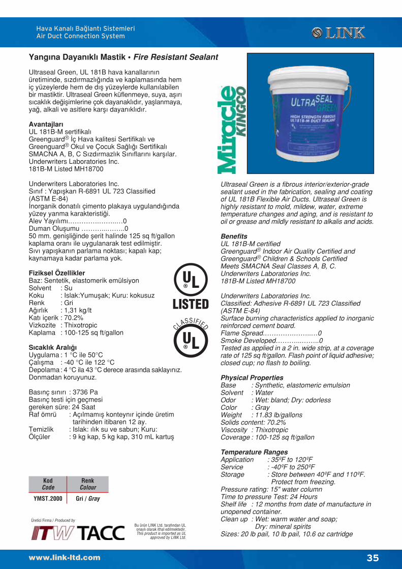
Yang›na Dayan›kl› Mastik • Fire Resistant Sealant
Ultraseal Green, UL 181B hava kanallar›n›nüretiminde, s›zd›rmazl›¤›nda ve kaplamas›nda hemiç yüzeylerde hem de d›fl yüzeylerde kullan›labilenbir mastiktir. Ultraseal Green küflenmeye, suya, afl›r›s›cakl›k de¤iflimlerine çok dayanakl›d›r, yafllanmaya,ya¤, alkali ve asitlere karfl› dayan›kl›d›r.
Avantajlar›UL 181B-M sertifikal›Greenguard® ‹ç Hava kalitesi Sertifikal› veGreenguard® Okul ve Çocuk Sa¤l›¤› Sertifikal›SMACNA A, B, C S›zd›rmazl›k S›n›flar›n› karfl›lar.Underwriters Laboratories Inc.181B-M Listed MH18700
Underwriters Laboratories Inc.S›n›f : Yap›flkan R-6891 UL 723 Classified(ASTM E-84)‹norganik donat›l› çimento plakaya uyguland›¤›ndayüzey yanma karakteristi¤i.Alev Yay›l›m›.………….……..…0Duman Oluflumu ………...……..050 mm. geniflli¤inde flerit halinde 125 sq ft/gallonkaplama oran› ile uygulanarak test edilmifltir.S›v› yap›flkan›n parlama noktas›; kapal› kap;kaynamaya kadar parlama yok.
Fiziksel ÖzelliklerBaz: Sentetik, elastomerik emülsiyonSolvent : SuKoku : Islak:Yumuflak; Kuru: kokusuzRenk : GriA¤›rl›k : 1,31 kg/ltKat› içerik : 70.2%Vizkozite : ThixotropicKaplama : 100-125 sq ft/gallon
S›cakl›k Aral›¤›Uygulama : 1 °C ile 50°CÇal›flma : -40 °C ile 122 °CDepolama: 4 °C ila 43 °C derece aras›nda saklay›n›z.Donmadan koruyunuz.
Bas›nç s›n›r› : 3736 PaBas›nç testi için geçmesigereken süre: 24 SaatRaf ömrü : Aç›lmam›fl konteyn›r içinde üretim
tarihinden itibaren 12 ay.Temizlik : Islak: ›l›k su ve sabun; Kuru:Ölçüler : 9 kg kap, 5 kg kap, 310 mL kartufl
Bu ürün LINK Ltd. taraf›ndan ULonayl› olarak ithal edilmektedir.This product is imported as UL
approved by LINK Ltd.
Ultraseal Green is a fibrous interior/exterior-gradesealant used in the fabrication, sealing and coatingof UL 181B Flexible Air Ducts. Ultraseal Green ishighly resistant to mold, mildew, water, extremetemperature changes and aging, and is resistant tooil or grease and mildly resistant to alkalis and acids.
BenefitsUL 181B-M certifiedGreenguard® Indoor Air Quality Certified andGreenguard® Children & Schools CertifiedMeets SMACNA Seal Classes A, B, C.Underwriters Laboratories Inc.181B-M Listed MH18700
Underwriters Laboratories Inc.Classified: Adhesive R-6891 UL 723 Classified(ASTM E-84)Surface burning characteristics applied to inorganicreinforced cement board.Flame Spread.………….……..…0Smoke Developed………...……..0Tested as applied in a 2 in. wide strip, at a coveragerate of 125 sq ft/gallon. Flash point of liquid adhesive;closed cup; no flash to boiling.
Physical PropertiesBase : Synthetic, elastomeric emulsionSolvent : WaterOdor : Wet: bland; Dry: odorlessColor : GrayWeight : 11.83 lb/gallonsSolids content: 70.2%Viscosity : ThixotropicCoverage : 100-125 sq ft/gallon
Temperature RangesApplication : 35ºF to 120ºFService : -40ºF to 250ºFStorage : Store between 40ºF and 110ºF.
Protect from freezing.Pressure rating: 15" water columnTime to pressure Test: 24 HoursShelf life : 12 months from date of manufacture inunopened container.Clean up : Wet: warm water and soap;
Dry: mineral spiritsSizes: 20 lb pail, 10 lb pail, 10.6 oz cartridge
Üretici Firma / Produced by
KodCode
RenkColour
YMST.2000 Gri / Gray
CLASSIFIED
36
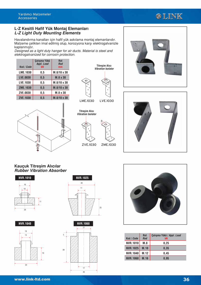
Havaland›rma kanallar› için hafif yük ask›lama montaj elemanlar›d›r.Malzeme çelikten imal edilmifl olup, korozyona karfl› elektrogalvanizlekaplanm›flt›r.Designed as a light duty hanger for air ducts. Material is steel andelektrogalvanized for corrosin protection.
Kod / Code
Çal›flma YüküAppl. Load
kN
LME.1030
LVE.0830
LVE.1030
ZME.1030
ZVE.0830
ZVE.1030
0,5
0,5
0,5
0,5
0,5
0,5
RotRodmm
M.8/10 x 30
M.8 x 30
M.8/10 x 30
M.8/10 x 30
M.8 x 30
M.8/10 x 30LME.1030 LVE.1030
Titreflim Al›c›Vibration Isolator
L-Z Kesitli Hafif Yük Montaj Elemanlar›L-Z Light Duty Mounting Elements
Yard›mc› MalzemelerAccessories
ZVE.1030 ZME.1030
R
Titreflim Al›c›Vibration Isolator
NVR.1010
NVR.1025
NVR.1040
NVR.1060
M.8
M.10
M.12
M.16
Kod / CodeÇal›flma Yükü / Appl. Load
kNRotRod
0,25
0,35
0,45
0,95
11
25
40
13
19
19
34
17
40
39
5
21
10
16
11
29
Kauçuk Titreflim Al›c›larRubber Vibration Absorber
NVR.1010 NVR.1025
NVR.1040 NVR.1060
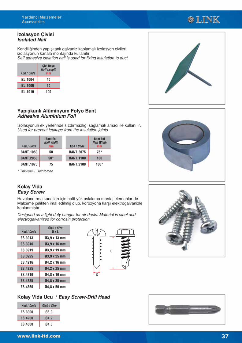
37
Kolay VidaEasy ScrewHavaland›rma kanallar› için hafif yük ask›lama montaj elemanlar›d›r.Malzeme çelikten imal edilmifl olup, korozyona karfl› elektrogalvanizlekaplanm›flt›r.
Designed as a light duty hanger for air ducts. Material is steel andelectrogalvanized for corrosin protection.
‹zolasyon ÇivisiIsolated Nail
Kendili¤inden yap›flkanl› galvaniz kaplamal› izolasyon çivileri,izolasyonun kanala montaj›nda kullan›l›r.Self adhesive isolation nail is used for fixing insulation to duct.
Yap›flkanl› Alüminyum Folyo BantAdhesive Aluminium Foil
‹zolasyonun ek yerlerinde s›zd›rmazl›¤› sa¤lamak amac› ile kullan›l›r.Used for prevent leakage from the insulation joints
Yard›mc› MalzemelerAccessories
Kod / Code
Çivi BoyuNail Length
mm
IZL.1004
IZL.1006
IZL.1010
40
60
100
Kod / Code
Bant EniNail Width
mm
BANT.1050
BANT.2050
BANT.1075
50
50*
75
Kod / Code
Bant EniNail Width
mm
BANT.2075
BANT.1100
BANT.2100
75*
100
100*
* Takviyeli / Reinforced
Kod / Code
ES.3913
ES.3916
ES.3919
ES.3925
ES.4216
ES.4225
ES.4816
ES.4835
ES.4850
Ø3,9 x 13 mm
Ø3,9 x 16 mm
Ø3,9 x 19 mm
Ø3,9 x 25 mm
Ø4,2 x 16 mm
Ø4,2 x 25 mm
Ø4,8 x 16 mm
Ø4,8 x 35 mm
Ø4,8 x 50 mm
Ölçü / SizeQ x L
L
Q
Kolay Vida Ucu / Easy Screw-Drill Head
Kod / Code
ES.3900
ES.4200
ES.4800
Ø3,9
Ø4,2
Ø4,8
Ölçü / Size
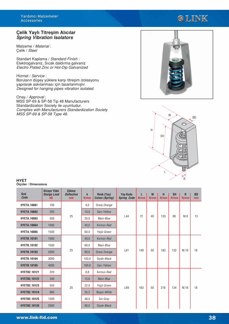
38
Çelik Yayl› Titreflim Al›c›larSpring Vibration Isolators
Malzeme / Material :Çelik / Steel
Standart Kaplama / Standard Finish :Elektrogalvaniz, S›cak dald›rma galvanizElectro Plated Zinc or Hot-Dip Galvanized
Hizmet / Service :Borular›n düfley yüklere karfl› titreflim izolasyonuyap›larak ask›lanmas› için tasarlanm›flt›r.Designed for hanging pipes vibration isolated.
Onay / Approval :MSS SP-69 & SP-58 Tip 48 ManufacturersStandardization Society ile uyumludur.Complies with Manufacturers Standardization SocietyMSS SP-69 & SP-58 Type 48.
Yard›mc› MalzemelerAccessories
HYETÖlçüler / Dimensions
KodCode
kN/mm
Renk (Yay)Colour (Spring)
HYETA.10081
HYETA.10082
HYETA.10083
HYETA.10084
HYETA.10085
HYETB.10101
HYETB.10102
HYETB.10103
HYETB.10104
HYETB.10105
HYETB2.10121
HYETB2.10122
HYETB2.10123
HYETB2.10124
HYETB2.10125
HYETB2.10126
Dizayn YüküDesign Load
kN
100
250
500
1000
1500
1000
1500
2000
3000
4000
220
340
550
880
1200
2000
ÇökmeDeflection
mm
25
25
25
4,0
10,0
20,0
40,0
60,0
40,0
60,0
80,0
120,0
160,0
8,8
13,6
22,0
35,2
48,0
80,0
Oranj-Orange
Sar›-Yellow
Mavi-Blue
K›rm›z›-Red
Yeflil-Green
K›rm›z›-Red
Mavi-Blue
Oranj-Orange
Siyah-Black
Sar›-Yellow
K›rm›z›-Red
Mavi-Blue
Yeflil-Green
Beyaz-White
Gri-Gray
Siyah-Black
Yay KoduSpring Code
L44
L61
L69
LN/mm
72
149
163
WN/mm
40
50
50
HN/mm
133
183
216
SHN/mm
90
132
134
RN/mm
M.8
M.10
M.16
ØDmm
13
18
18
H
SH
L
WØD
R
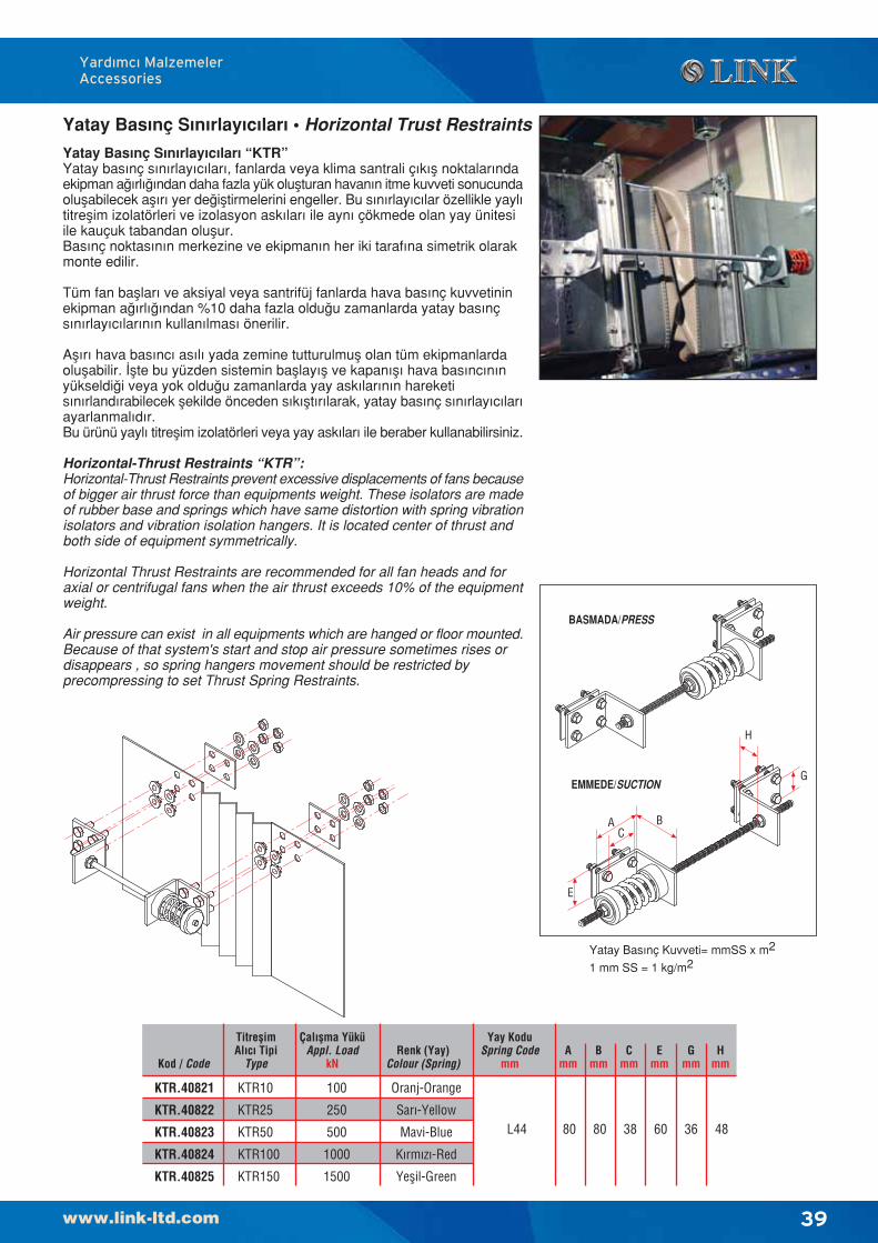
39
Yatay Bas›nç S›n›rlay›c›lar› “KTR”Yatay bas›nç s›n›rlay›c›lar›, fanlarda veya klima santrali ç›k›fl noktalar›ndaekipman a¤›rl›¤›ndan daha fazla yük oluflturan havan›n itme kuvveti sonucundaoluflabilecek afl›r› yer de¤ifltirmelerini engeller. Bu s›n›rlay›c›lar özellikle yayl›titreflim izolatörleri ve izolasyon ask›lar› ile ayn› çökmede olan yay ünitesiile kauçuk tabandan oluflur.Bas›nç noktas›n›n merkezine ve ekipman›n her iki taraf›na simetrik olarakmonte edilir.
Tüm fan bafllar› ve aksiyal veya santrifüj fanlarda hava bas›nç kuvvetininekipman a¤›rl›¤›ndan %10 daha fazla oldu¤u zamanlarda yatay bas›nçs›n›rlay›c›lar›n›n kullan›lmas› önerilir.
Afl›r› hava bas›nc› as›l› yada zemine tutturulmufl olan tüm ekipmanlardaoluflabilir. ‹flte bu yüzden sistemin bafllay›fl ve kapan›fl› hava bas›nc›n›nyükseldi¤i veya yok oldu¤u zamanlarda yay ask›lar›n›n hareketis›n›rland›rabilecek flekilde önceden s›k›flt›r›larak, yatay bas›nç s›n›rlay›c›lar›ayarlanmal›d›r.Bu ürünü yayl› titreflim izolatörleri veya yay ask›lar› ile beraber kullanabilirsiniz.
Horizontal-Thrust Restraints “KTR”:Horizontal-Thrust Restraints prevent excessive displacements of fans becauseof bigger air thrust force than equipments weight. These isolators are madeof rubber base and springs which have same distortion with spring vibrationisolators and vibration isolation hangers. It is located center of thrust andboth side of equipment symmetrically.
Horizontal Thrust Restraints are recommended for all fan heads and foraxial or centrifugal fans when the air thrust exceeds 10% of the equipmentweight.
Air pressure can exist in all equipments which are hanged or floor mounted.Because of that system's start and stop air pressure sometimes rises ordisappears , so spring hangers movement should be restricted byprecompressing to set Thrust Spring Restraints.
Yard›mc› MalzemelerAccessories
Yatay Bas›nç S›n›rlay›c›lar› • Horizontal Trust Restraints
Kod / Code
TitreflimAl›c› Tipi
Type
KTR.40821
KTR.40822
KTR.40823
KTR.40824
KTR.40825
KTR10
KTR25
KTR50
KTR100
KTR150
Çal›flma YüküAppl. Load
kN
100
250
500
1000
1500
Renk (Yay)Colour (Spring)
Yay KoduSpring Code
mmA
mmB
mmC
mmE
mmG
mmH
mm
Oranj-Orange
Sar›-Yellow
Mavi-Blue
K›rm›z›-Red
Yeflil-Green
L44 80 80 38 60 36 48
Yatay Bas›nç Kuvveti= mmSS x m2
1 mm SS = 1 kg/m2
AC
G
E
H
B
BASMADA/PRESS
EMMEDE/SUCTION
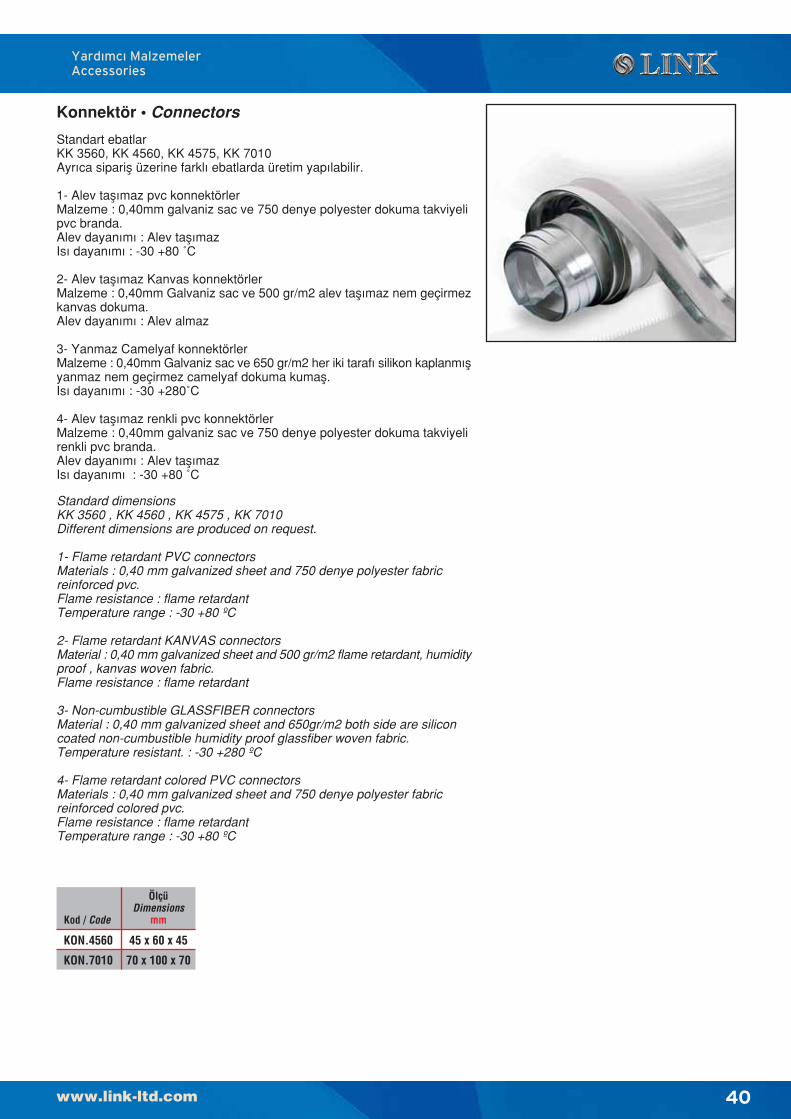
40
Yard›mc› MalzemelerAccessories
Konnektör • Connectors
Standart ebatlarKK 3560, KK 4560, KK 4575, KK 7010Ayr›ca siparifl üzerine farkl› ebatlarda üretim yap›labilir.
1- Alev tafl›maz pvc konnektörlerMalzeme : 0,40mm galvaniz sac ve 750 denye polyester dokuma takviyelipvc branda.Alev dayan›m› : Alev tafl›mazIs› dayan›m› : -30 +80 ˚C
2- Alev tafl›maz Kanvas konnektörlerMalzeme : 0,40mm Galvaniz sac ve 500 gr/m2 alev tafl›maz nem geçirmezkanvas dokuma.Alev dayan›m› : Alev almaz
3- Yanmaz Camelyaf konnektörlerMalzeme : 0,40mm Galvaniz sac ve 650 gr/m2 her iki taraf› silikon kaplanm›flyanmaz nem geçirmez camelyaf dokuma kumafl.Is› dayan›m› : -30 +280˚C
4- Alev tafl›maz renkli pvc konnektörlerMalzeme : 0,40mm galvaniz sac ve 750 denye polyester dokuma takviyelirenkli pvc branda.Alev dayan›m› : Alev tafl›mazIs› dayan›m› : -30 +80 ˚C
Standard dimensionsKK 3560 , KK 4560 , KK 4575 , KK 7010Different dimensions are produced on request.
1- Flame retardant PVC connectorsMaterials : 0,40 mm galvanized sheet and 750 denye polyester fabricreinforced pvc.Flame resistance : flame retardantTemperature range : -30 +80 ºC
2- Flame retardant KANVAS connectorsMaterial : 0,40 mm galvanized sheet and 500 gr/m2 flame retardant, humidityproof , kanvas woven fabric.Flame resistance : flame retardant
3- Non-cumbustible GLASSFIBER connectorsMaterial : 0,40 mm galvanized sheet and 650gr/m2 both side are siliconcoated non-cumbustible humidity proof glassfiber woven fabric.Temperature resistant. : -30 +280 ºC
4- Flame retardant colored PVC connectorsMaterials : 0,40 mm galvanized sheet and 750 denye polyester fabricreinforced colored pvc.Flame resistance : flame retardantTemperature range : -30 +80 ºC
Kod / Code
ÖlçüDimensions
mm
KON.4560
KON.7010
45 x 60 x 45
70 x 100 x 70
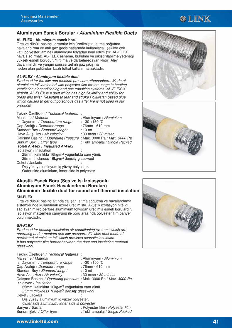
41
Yard›mc› MalzemelerAccessories
Aluminyum Esnek Borular • Aluminium Flexible Ducts
SN-FLEXOrta ve düflük basınç altında çalıflan ısıtma so¤utma ve havalandırmasistemlerinde kullanılmak üzere üretilmifltir. Akustik izolasyon niteli¤isa¤layan mikro perfore aluminyum folyodan üretilmifl esnek borulardır.‹zolasyon malzemesi camyünü ile boru arasında polyester film bariyerbulunmaktadır.
SN-FLEXProduced for heating ventilation air conditioning systems which areoperating under medium and low pressure. Flexible duct made ofperforated aluminium foil which provides acoustic insulation.It has polyester film barrier between the duct and insulation materialglasswool.
Teknik Özellikleri / Technical features :Malzeme / Material : Aluminyum / AluminiumIs› Dayan›m› / Temperature range : -30 +150 ˚CÇap Aral›¤› / Diameter range : 76mm - 610 mmStandart Boy / Standard lenght : 10 mtHava Ak›fl H›z› / Air velocity : 30 m/sn / 30 m/sec.Çal›flma Bas›nc› / Operating pressure : Mak. 3000 Pa / Max. 3000 Pa‹zolasyon / Insulation :
25mm. kal›nl›kta 16kg/m3 yo¤unlukta cam yünü.25mm thickness 16kg/m3 density glasswool
Ceket / Jackets :D›fl yüzey aluminyum iç yüzey polyester.Outer side aluminium, inner side is polyester
Bariyer / Barrier : Polyester film / Polyester filmSunum fiekli / Offer type : Tekli ambalaj / Single Packed
Akustik Esnek Boru (Ses ve Is› ‹zolasyonluAluminyum Esnek Havaland›rma Borular›)Aluminium flexible duct for sound and thermal insulation
AL-FLEX : Aluminyum esnek boruOrta ve düflük bas›nçl› ortamlar için üretilmifltir. Is›tma-so¤utmahavaland›rma ve at›k gaz geçifl hatlar›nda kullan›lacak flekilde çokkatl› polyester lamineli aluminyum folyadan imal edilmifltir. AL-FLEXhava s›zd›rmaz. AL-FLEX esneme, bükülme ve s›k›flt›r›labilme yetene¤iyüksek esnek borudur. Y›rt›lma ve darbeleredayan›kl›d›r. Alevdayan›ml›d›r ve yang›n sonras› zehirli gaz ç›k›fl›naneden olan poliüretan bazl› tutkal kullan›lmamaktad›r.
AL-FLEX : Aluminyum flexible ductProduced for the low and medium pressure athmosphere. Made ofaluminium foil laminated with polyester film for the usage in heatingventilation air conditioning and gas transition systems. AL-FLEX isairtight. AL-FLEX is a duct which has high flexibility and ability forpress and twist. Resistant to tear and stroke Poliuretan based gluewhich causes to get out poisonous gas after fire is not used in ourproducts
Teknik Özellikleri / Technical features :Malzeme / Material : Aluminyum / AluminiumIs› Dayan›m› / Temperature range : -30 +150 ˚CÇap Aral›¤› / Diameter range : 76mm - 610 mmStandart Boy / Standard lenght : 10 mtHava Ak›fl H›z› / Air velocity : 30 m/sn / 30 m/sec.Çal›flma Bas›nc› / Operating Pressure : Mak. 3000 Pa / Max. 3000 PaSunum fiekli / Offer type : Tekli ambalaj / Single Packed‹zoleli Al-Flex / Insulated Al-Flex‹zolasyon / Insulation :
25mm. kal›nl›kta 16kg/m3 yo¤unlukta cam yünü.25mm thickness 16kg/m3 density glasswool
Ceket / Jackets :D›fl yüzey aluminyum iç yüzey polyester.Outer side aluminium, inner side is polyester
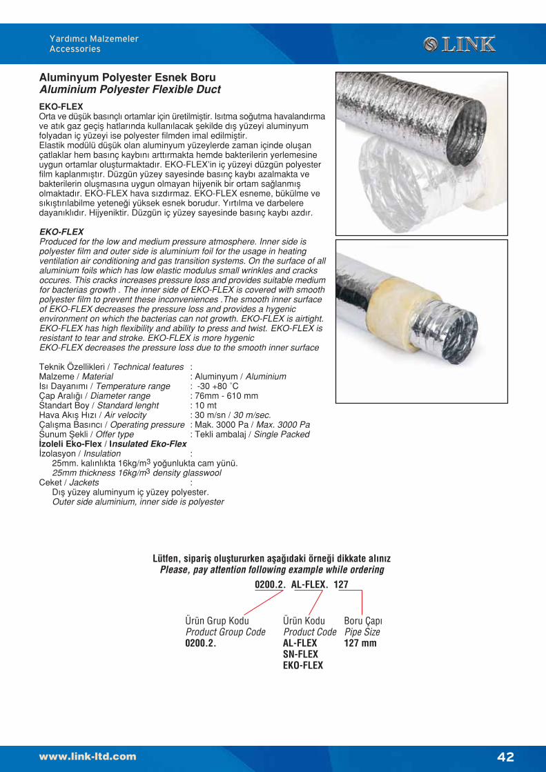
42
Yard›mc› MalzemelerAccessories
EKO-FLEXOrta ve düflük basınçlı ortamlar için üretilmifltir. Isıtma so¤utma havalandırmave atık gaz geçifl hatlarında kullanılacak flekilde dıfl yüzeyi aluminyumfolyadan iç yüzeyi ise polyester filmden imal edilmifltir.Elastik modülü düflük olan aluminyum yüzeylerde zaman içinde oluflançatlaklar hem basınç kaybını arttırmakta hemde bakterilerin yerlemesineuygun ortamlar oluflturmaktadır. EKO-FLEX’in iç yüzeyi düzgün polyesterfilm kaplanmıfltır. Düzgün yüzey sayesinde basınç kaybı azalmakta vebakterilerin oluflmasına uygun olmayan hijyenik bir ortam sa¤lanmıflolmaktadır. EKO-FLEX hava sızdırmaz. EKO-FLEX esneme, bükülme vesıkıfltırılabilme yetene¤i yüksek esnek borudur. Yırtılma ve darbeleredayanıklıdır. Hijyeniktir. Düzgün iç yüzey sayesinde basınç kaybı azdır.
EKO-FLEXProduced for the low and medium pressure atmosphere. Inner side ispolyester film and outer side is aluminium foil for the usage in heatingventilation air conditioning and gas transition systems. On the surface of allaluminium foils which has low elastic modulus small wrinkles and cracksoccures. This cracks increases pressure loss and provides suitable mediumfor bacterias growth . The inner side of EKO-FLEX is covered with smoothpolyester film to prevent these inconveniences .The smooth inner surfaceof EKO-FLEX decreases the pressure loss and provides a hygenicenvironment on which the bacterias can not growth. EKO-FLEX is airtight.EKO-FLEX has high flexibility and ability to press and twist. EKO-FLEX isresistant to tear and stroke. EKO-FLEX is more hygenicEKO-FLEX decreases the pressure loss due to the smooth inner surface
Teknik Özellikleri / Technical features :Malzeme / Material : Aluminyum / AluminiumIs› Dayan›m› / Temperature range : -30 +80 ˚CÇap Aral›¤› / Diameter range : 76mm - 610 mmStandart Boy / Standard lenght : 10 mtHava Ak›fl H›z› / Air velocity : 30 m/sn / 30 m/sec.Çal›flma Bas›nc› / Operating pressure : Mak. 3000 Pa / Max. 3000 PaSunum fiekli / Offer type : Tekli ambalaj / Single Packed‹zoleli Eko-Flex / Insulated Eko-Flex ‹zolasyon / Insulation :
25mm. kal›nl›kta 16kg/m3 yo¤unlukta cam yünü.25mm thickness 16kg/m3 density glasswool
Ceket / Jackets :D›fl yüzey aluminyum iç yüzey polyester.Outer side aluminium, inner side is polyester
Aluminyum Polyester Esnek BoruAluminium Polyester Flexible Duct
Lütfen, siparifl olufltururken afla¤›daki örne¤i dikkate al›n›zPlease, pay attention following example while ordering
0200.2. AL-FLEX. 127
Ürün KoduProduct CodeAL-FLEXSN-FLEXEKO-FLEX
Boru Çap›Pipe Size127 mm
Ürün Grup KoduProduct Group Code0200.2.
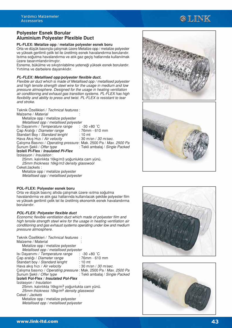
43
Yard›mc› MalzemelerAccessories
Polyester Esnek BorularAluminium Polyester Plexible DuctPL-FLEX: Metalize opp / metalize polyester esnek boruOrta ve düflük bas›nçta çal›flmak üzere Metalize opp / metalize polyesterve yüksek gerilimli çelik tel ile üretilmifl esnek havaland›rma borular›d›r.Is›tma so¤utma havaland›rma ve at›k gaz geçifl hatlar›nda kullan›lmaküzere tasarımlandırılmıfltır.Esneme, bükülme ve sıkıfltırılabilme yetene¤i yüksek esnek borulardır.Yırtılma ve darbelere dayanıklıdır.
PL-FLEX: Metallised opp/polyester flexible duct.Flexible air duct which is made of Metallised opp / metallised polyesterand high tensile strength steel wire for the usage in medium and lowpressure atmosphere. Designed for the usage in heating ventilationair conditioning and exhaust gas transition systems. PL-FLEX has highflexibility and ability to press and twist. PL-FLEX is resistant to tearand stroke.
Teknik Özellikleri / Technical features :Malzeme / Material :
Metalize opp / metalize polyesterMetallised opp / metallised polyester
Is› Dayan›m› / Temperature range : -30 +80 ˚CÇap Aral›¤› / Diameter range : 76mm - 610 mmStandart Boy / Standard lenght : 10 mtHava Ak›fl H›z› / Air velocity : 30 m/sn / 30 m/sec.Çal›flma Bas›nc› / Operating pressure : Mak. 2500 Pa / Max. 2500 PaSunum fiekli / Offer type : Tekli ambalaj / Single Packed‹zoleli Pl-Flex / Insulated Pl-Flex ‹zolasyon / Insulation :
25mm. kal›nl›kta 16kg/m3 yo¤unlukta cam yünü.25mm thickness 16kg/m3 density glasswool
Ceket/Jackets :Metalize opp / metalize polyesterMetallised opp / metallised polyester
POL-FLEX: Polyester esnek boruOrta ve düflük basınç altıda çalıflmak üzere ısıtma so¤utmahavalandırma ve atık gaz hatlarında kullanılacak flekilde polyester filmve yüksek gerilimli çelik tel ile üretilmifl ekonomik esnek havalandırmaborularıdır.
POL-FLEX: Polyester flexible ductEconomic flexible ventilation duct which made of polyester film andhigh tensile strength steel wire for the usage in heating ventilation airconditioning and gas exhaust systems operating under low and mediumpressure atmosphere.
Teknik Özellikleri / Technical features :Malzeme / Material :
Metalize opp / metalize polyesterMetallised opp / metallised polyester
Is› Dayan›m› / Temperature range : -30 +80 ˚CÇap aral›¤› / Diameter range : 76mm - 610 mmStandart boy / Standard lenght : 10 mtHava ak›fl h›z› / Air velocity : 30 m/sn / 30 m/sec.Çal›flma bas›nc› / Operating pressure : Mak. 2500 Pa / Max. 2500 PaSunum fiekli / Offer type : Tekli ambalaj / Single Packed‹zoleli Pol-Flex / Insulated Pol-Flex‹zolasyon / Insulation :
25mm. kal›nl›kta 16kg/m3 yo¤unlukta cam yünü.25mm thickness 16kg/m3 density glasswool
Ceket / Jackets :Metalize opp / metalize polyesterMetallised opp / metallised polyester
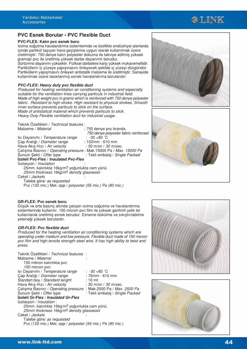
44
Yard›mc› MalzemelerAccessories
PVC Esnek Borular • PVC Flexible DuctPVC-FLEX: Kalın pvc esnek boruIsıtma so¤utma havalandırma sistemlerinde ve özellikle endüstriyel alanlardaiçinde partikül taflıyan hava geçifllerine uygun olarak kullanılmak üzereüretilmifltir. 750 denye kalın polyester dokuma ile takviye edilmifl yüksekgramajlı pvc ile üretilmifl yüksek darbe dayanımlı borudur.Sürtünme dayanımı yüksektir. Fiziksel darbelere karflı yüksek mukavemetlidir.Partiküllerin iç yüzeye yapıflmasını önleyecek flekilde iç yüzeyi düzgündür.Partiküllerin yapıflmasını önleyen antistatik malzeme ile üretilmifltir. Sanayidekullanılmak üzere tasarlanmıfl esnek havalandırma borularıdır.
PVC-FLEX: Heavy duty pvc flexible ductProduced for heating ventilation air conditioning systems and especiallysuitable for the ventilation lines carrying particuls in industrial field.Made of high weight pvc in grams which is reinforced with 750 denye polyesterfabric . Resistant to high stroke. High resistant to physical strokes. Smoothinner surface prevents particuls to stick on the surface.Made of antistatical material which prevents particuls to stick.Heavy Duty Flexible ventilation duct for industrial usage.
Teknik Özellikleri / Technical features :Malzeme / Material : 750 denye pvc branda
750 denye polyester fabric reinforcedIs› Dayan›m› / Temperature range : -30 +80 ˚CÇap Aral›¤› / Diameter range : 102mm - 610 mmHava Ak›fl H›z› / Air velocity : 30 m/sn / 30 m/sec.Çal›flma Bas›nc› / Operating pressure : Mak.15000 Pa / Max. 15000 PaSunum fiekli / Offer type : Tekli ambalaj / Single Packed‹zoleli Pvc-Flex / Insulated Pvc-Flex‹zolasyon / Insulation :
25mm. kal›nl›kta 16kg/m3 yo¤unlukta cam yünü.25mm thickness 16kg/m3 density glasswool
Ceket / Jackets :Talebe göre/ as requestedPvc (120 mic.) Met. opp / polyester (55 mic.) Pe (80 mic.)
GR-FLEX: Pvc esnek boruDüflük ve orta basınç altında çalıflan ısıtma so¤utma ve havalandırmasistemlerinde kullanılır. 150 micron pvc film ile yüksek gerilimli çelik telkullanılarak üretilmifl esnek borudur. Esneme bükülme ve sıkıfltırılabilmeyetene¤i yüksek borulardır.
GR-FLEX: Pvc flexible ductProduced for the heating ventilation air conditioning systems which areoperating under medium and low pressure. Flexible duct made of 150 micronpvc film and high tensile strength steel wire. It has high ability to twist andpress.
Teknik Özellikleri / Technical features :Malzeme / Material :
150 mikron kal›nl›kta pvc150 micron pvc
Is› Dayan›m› / Temperature range : -30 +80 ˚CÇap Aral›¤› / Diameter range : 76mm - 610 mmStandart boy / Standard lenght : 10 mtHava Ak›fl H›z› / Air velocity : 30 m/sn / 30 m/sec.Çal›flma Bas›nc› / Operating pressure : Mak.2500 Pa / Max. 2500 PaSunum fiekli / Offer type : Tekli ambalaj / Single Packed‹zoleli Gr-Flex / Insulated Gr-Flex ‹zolasyon / Insulation :
25mm. kal›nl›kta 16kg/m3 yo¤unlukta cam yünü.25mm thickness 16kg/m3 density glasswool
Ceket / Jackets :Talebe göre/ as requestedPvc (120 mic.) Met. opp / polyester (55 mic.) Pe (80 mic.)
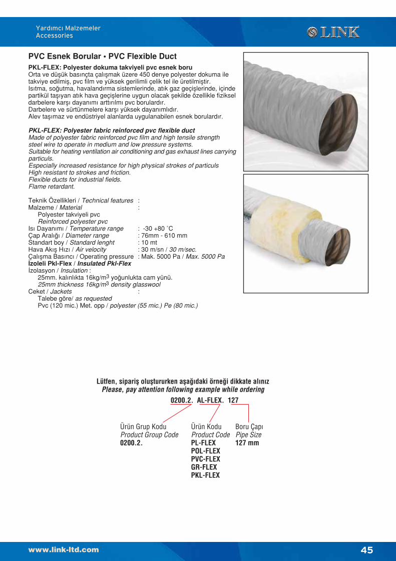
45
Yard›mc› MalzemelerAccessories
PVC Esnek Borular • PVC Flexible DuctPKL-FLEX: Polyester dokuma takviyeli pvc esnek boruOrta ve düflük basınçta çalıflmak üzere 450 denye polyester dokuma iletakviye edilmifl, pvc film ve yüksek gerilimli çelik tel ile üretilmifltir.Isıtma, so¤utma, havalandırma sistemlerinde, atık gaz geçifllerinde, içindepartikül taflıyan atık hava geçifllerine uygun olacak flekilde özellikle fizikseldarbelere karflı dayanımı arttırılmı pvc borulardır.Darbelere ve sürtünmelere karflı yüksek dayanımlıdır.Alev taflımaz ve endüstriyel alanlarda uygulanabilen esnek borulardır.
PKL-FLEX: Polyester fabric reinforced pvc flexible ductMade of polyester fabric reinforced pvc film and high tensile strengthsteel wire to operate in medium and low pressure systems.Suitable for heating ventilation air conditioning and gas exhaust lines carryingparticuls.Especially increased resistance for high physical strokes of particulsHigh resistant to strokes and friction.Flexible ducts for industrial fields.Flame retardant.
Teknik Özellikleri / Technical features :Malzeme / Material :
Polyester takviyeli pvcReinforced polyester pvc
Is› Dayan›m› / Temperature range : -30 +80 ˚CÇap Aral›¤› / Diameter range : 76mm - 610 mmStandart boy / Standard lenght : 10 mtHava Ak›fl H›z› / Air velocity : 30 m/sn / 30 m/sec.Çal›flma Bas›nc› / Operating pressure : Mak. 5000 Pa / Max. 5000 Pa‹zoleli Pkl-Flex / Insulated Pkl-Flex‹zolasyon / Insulation :
25mm. kal›nl›kta 16kg/m3 yo¤unlukta cam yünü.25mm thickness 16kg/m3 density glasswool
Ceket / Jackets : Talebe göre/ as requestedPvc (120 mic.) Met. opp / polyester (55 mic.) Pe (80 mic.)
Lütfen, siparifl olufltururken afla¤›daki örne¤i dikkate al›n›zPlease, pay attention following example while ordering
0200.2. AL-FLEX. 127
Ürün KoduProduct CodePL-FLEXPOL-FLEXPVC-FLEXGR-FLEXPKL-FLEX
Boru Çap›Pipe Size127 mm
Ürün Grup KoduProduct Group Code0200.2.
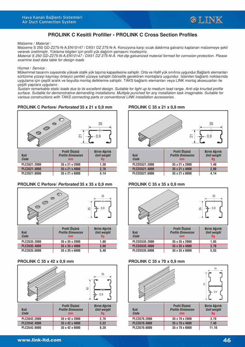
46
Hava Kanal› Ba¤lant› SistemleriAir Duct Connection System
PROLINK C Kesitli Profiller • PROLINK C Cross Section Profiles
Malzeme / Material :Malzeme S 250 GD-Z275-N-A,EN10147 / DX51 DZ 275-N-A. Korozyona karfl› s›cak dald›rma galvaniz kaplanan malzemeye flekilvererek üretilmifltir. Yükleme bilgileri için profil yük da¤›l›m flemas›n› inceleyiniz.Material S 250 GD-Z275-N-A,EN10147 / DX51 DZ 275-N-A. Hot-dip galvanized material formed for corrosion protection. Pleaseexamine load data table for design loads
Hizmet / Service :Mükemmel tasar›m› sayesinde yüksek statik yük tafl›ma kapasitesine sahiptir. Orta ve Hafif yük s›n›f›na uygundur.Ba¤lant› elemanlar›sürtünme yüzeyi kaymay› önleyici çentikli yüzeye sahiptir.Görsellik gerektiren montajlara uygundur. ‹stenilen ba¤lant› noktas›ndauygulama için çeflitli aral›k ve boyutta montaj deliklerine sahiptir. TAKS ba¤lant› elemanlar› veya LINK montaj aksesuarlar› ileçeflitli yap›lara uygulan›r.Sustain remarkable static loads due to its excellent design. Suitable for light up to medium load range. Anti-slip knurled profilesurface. Suitable for demonstrative demanding installations. Multiple punched for any installation task imaginable. Suitable forvarious constructions with TAKS connecting parts or conventional LINK installation accessories.
0,9
35
35
0,9
35
42
0,9
3535
0,9
35
70
0,9
35
21
PROLINK C Perfore/ Perforated 35 x 21 x 0,9 mm
0,9
35
21
KodCode
Profil ÖlçüsüProfile Dimension
mm
35 x 21 x 200035 x 21 x 400035 x 21 x 6000
PLC3521.2000PLC3521.4000PLC3521.6000
Birim A¤›rl›kUnit weight
Kg
1,382,764,14
KodCode
Profil ÖlçüsüProfile Dimension
mm
35 x 21 x 200035 x 21 x 400035 x 21 x 6000
PLCD3521.2000PLCD3521.4000PLCD3521.6000
Birim A¤›rl›kUnit weight
Kg
1,402,804,14
KodCode
Profil ÖlçüsüProfile Dimension
mm
35 x 35 x 200035 x 35 x 400035 x 35 x 6000
PLC3535.2000PLC3535.4000PLC3535.6000
Birim A¤›rl›kUnit weight
Kg
1,803,605,40
KodCode
Profil ÖlçüsüProfile Dimension
mm
35 x 35 x 200035 x 35 x 400035 x 35 x 6000
PLCD3535.2000PLCD3535.4000PLCD3535.6000
Birim A¤›rl›kUnit weight
Kg
1,853,705,55
KodCode
Profil ÖlçüsüProfile Dimension
mm
35 x 42 x 200035 x 42 x 400035 x 42 x 6000
PLC3542.2000PLC3542.4000PLC3542.6000
Birim A¤›rl›kUnit weight
Kg
2,765,528,28
KodCode
Profil ÖlçüsüProfile Dimension
mm
35 x 70 x 200035 x 70 x 400035 x 70 x 6000
PLC3570.2000PLC3570.4000PLC3570.6000
Birim A¤›rl›kUnit weight
Kg
3,707,4011,10
PROLINK C 35 x 21 x 0,9 mm
PROLINK C Perfore/ Perforated 35 x 35 x 0,9 mm PROLINK C 35 x 35 x 0,9 mm
PROLINK C 35 x 42 x 0,9 mm PROLINK C 35 x 70 x 0,9 mm
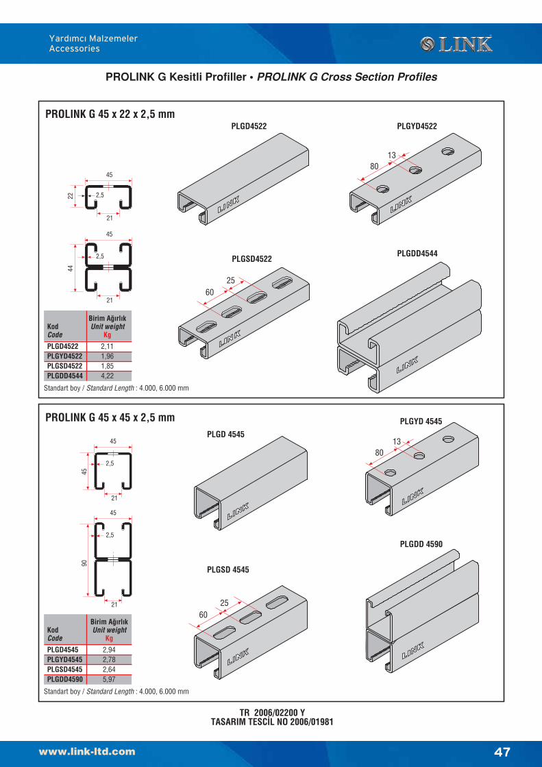
47
Yard›mc› MalzemelerAccessories
PROLINK G 45 x 22 x 2,5 mm
2,5
45
22
21
2,5
45
44
21
PLGD4522 PLGYD4522
PLGSD4522PLGDD4544
6025
8013
TR 2006/02200 YTASARIM TESC‹L NO 2006/01981
PROLINK G 45 x 45 x 2,5 mm
2,5
45
45
21
2,5
90
45
21
PLGD 4545
PLGYD 4545
PLGSD 4545
PLGDD 4590
8013
6025
Standart boy / Standard Length : 4.000, 6.000 mm
KodCode
PLGD4522PLGYD4522PLGSD4522PLGDD4544
Birim A¤›rl›kUnit weight
Kg
2,111,961,854,22
Standart boy / Standard Length : 4.000, 6.000 mm
KodCode
PLGD4545PLGYD4545PLGSD4545PLGDD4590
Birim A¤›rl›kUnit weight
Kg
2,942,782,645,97
PROLINK G Kesitli Profiller • PROLINK G Cross Section Profiles
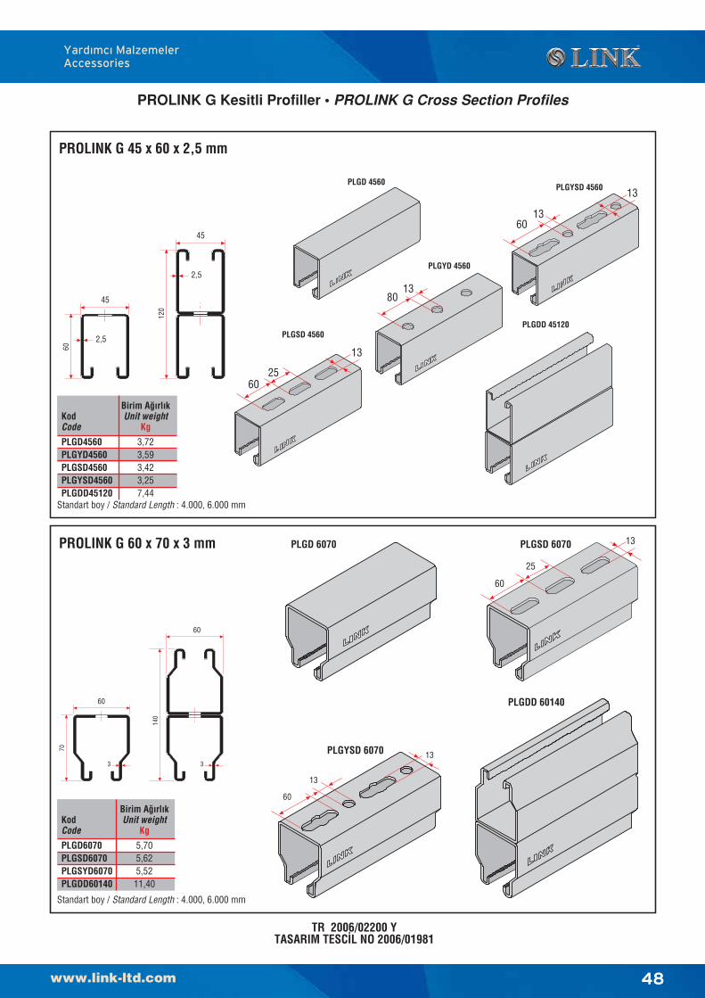
48
Yard›mc› MalzemelerAccessories
PROLINK G 45 x 60 x 2,5 mm
TR 2006/02200 YTASARIM TESC‹L NO 2006/01981
PROLINK G 60 x 70 x 3 mm
Standart boy / Standard Length : 4.000, 6.000 mm
Standart boy / Standard Length : 4.000, 6.000 mm
KodCode
PLGD6070PLGSD6070PLGSYD6070PLGDD60140
Birim A¤›rl›kUnit weight
Kg
5,705,625,5211,40
45
2,5
60
2,5
120
45
60
70
3
140
3
60
60
25
13
60
13
13
PLGD 6070 PLGSD 6070
PLGYSD 6070
PLGDD 60140
PLGYD 4560
PLGSD 4560PLGDD 45120
PLGYSD 4560PLGD 4560
KodCode
PLGD4560PLGYD4560PLGSD4560PLGYSD4560PLGDD45120
Birim A¤›rl›kUnit weight
Kg
3,723,593,423,257,44
1380
2560
13
1360
13
PROLINK G Kesitli Profiller • PROLINK G Cross Section Profiles
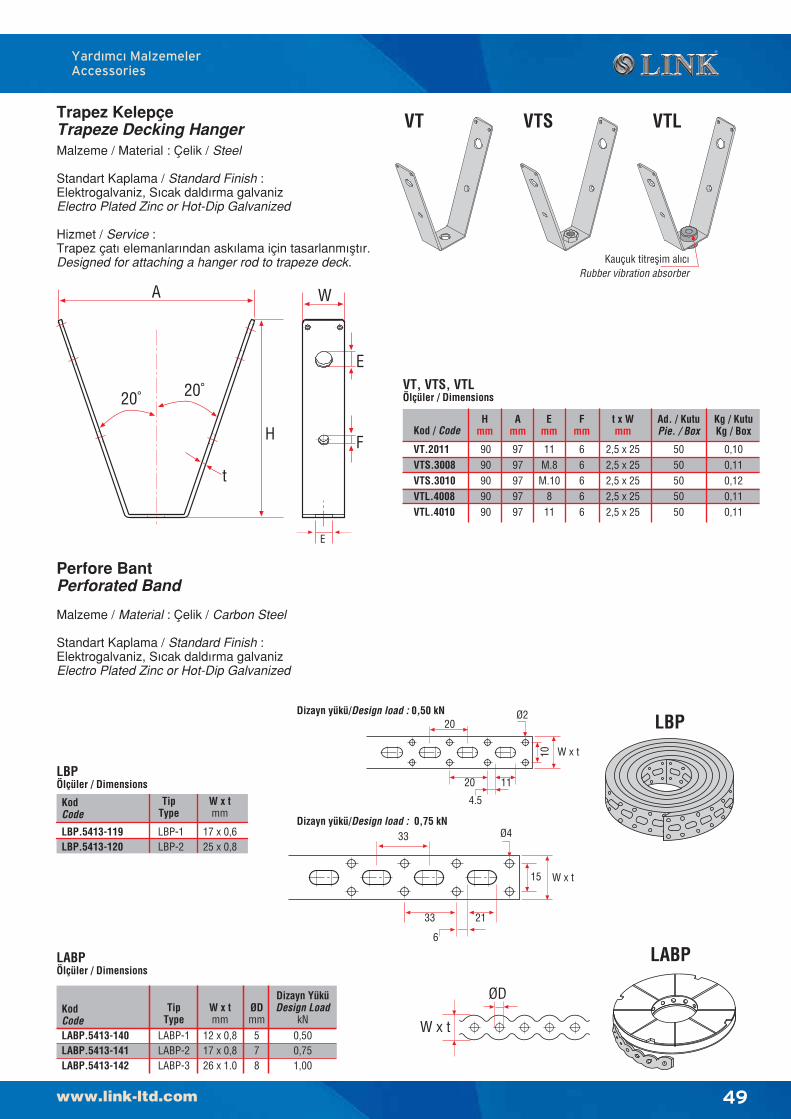
KodCode
W x tmm
17 x 0,625 x 0,8
LBP-1LBP-2
TipType
LBP.5413-119LBP.5413-120
49
Yard›mc› MalzemelerAccessories
Trapez KelepçeTrapeze Decking Hanger
Perfore BantPerforated Band
Malzeme / Material : Çelik / Carbon Steel
Standart Kaplama / Standard Finish :Elektrogalvaniz, S›cak dald›rma galvanizElectro Plated Zinc or Hot-Dip Galvanized
LBPÖlçüler / Dimensions
LABPLABPÖlçüler / Dimensions
ØD
W x t
21
Dizayn yükü/Design load : 0,50 kN20
10
20 11
4.5
Dizayn yükü/Design load : 0,75 kN33
15
33
6
Ø4
Ø2 LBP
W x t
W x t
Malzeme / Material : Çelik / Steel
Standart Kaplama / Standard Finish :Elektrogalvaniz, S›cak dald›rma galvanizElectro Plated Zinc or Hot-Dip Galvanized
Hizmet / Service :Trapez çat› elemanlar›ndan ask›lama için tasarlanm›flt›r.Designed for attaching a hanger rod to trapeze deck.
VT.2011VTS.3008VTS.3010VTL.4008VTL.4010
Hmm
9090909090
Amm
0,100,110,120,110,11
Kg / KutuKg / Box
9797979797
Ad. / KutuPie. / Box
5050505050
Kod / CodeE
mm
11M.8M.10
811
Fmm
66666
t x Wmm
2,5 x 252,5 x 252,5 x 252,5 x 252,5 x 25
E
W
E
F
VTS
Kauçuk titreflim al›c›Rubber vibration absorber
VT VTL
H
t
A
20˚ 20˚ VT, VTS, VTLÖlçüler / Dimensions
KodCode
W x tmm
TipType
ØDmm
Dizayn YüküDesign Load
kN12 x 0,817 x 0,826 x 1.0
LABP-1LABP-2LABP-3
LABP.5413-140LABP.5413-141LABP.5413-142
578
0,500,751,00
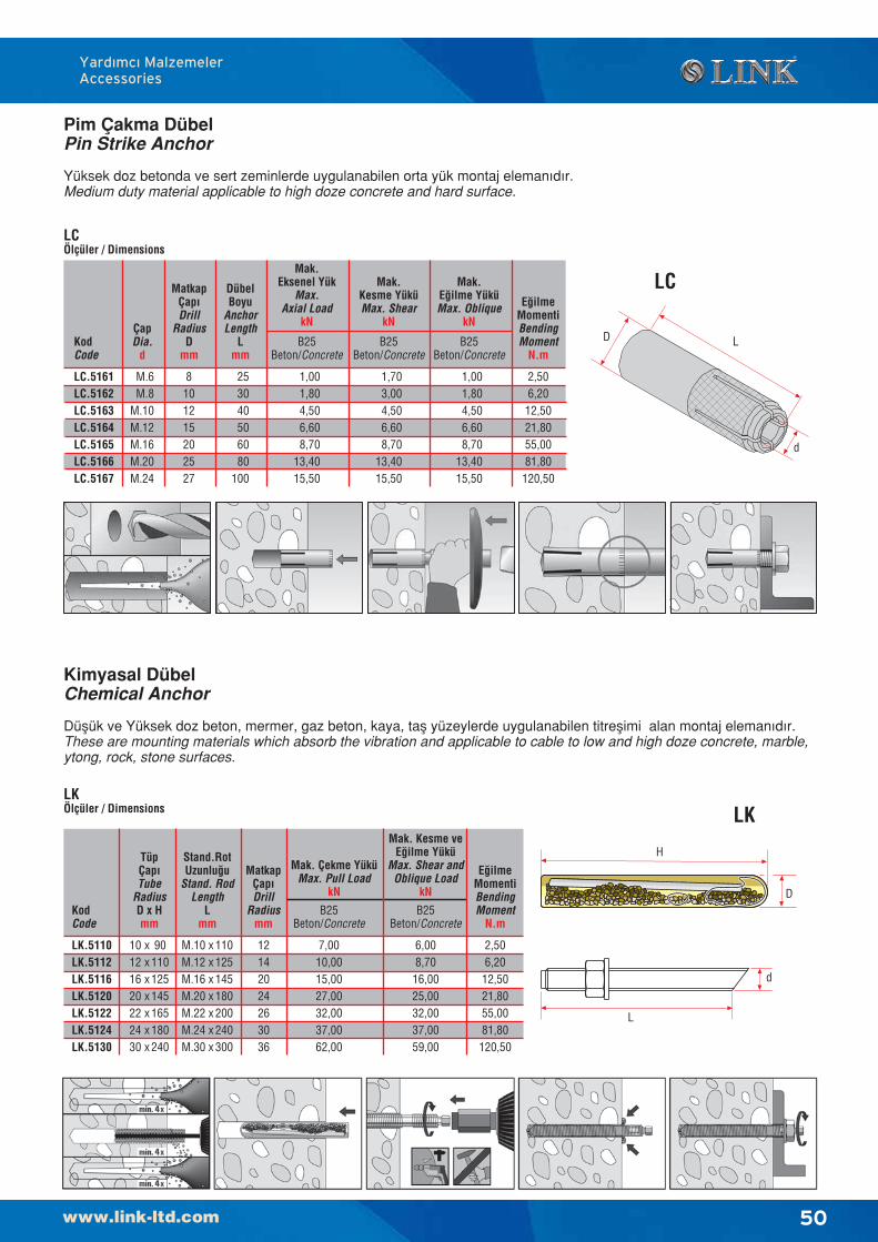
50
Yard›mc› MalzemelerAccessories
LK
Kimyasal DübelChemical Anchor
Düflük ve Yüksek doz beton, mermer, gaz beton, kaya, tafl yüzeylerde uygulanabilen titreflimi alan montaj eleman›d›r.These are mounting materials which absorb the vibration and applicable to cable to low and high doze concrete, marble,ytong, rock, stone surfaces.
LKÖlçüler / Dimensions
KodCode
LK.5110LK.5112LK.5116LK.5120LK.5122LK.5124LK.5130
2,506,2012,5021,8055,0081,80120,50
E¤ilmeMomentiBendingMoment
N.m
Mak. Kesme veE¤ilme Yükü
Max. Shear andOblique Load
kN
B25Beton/Concrete
6,008,7016,0025,0032,0037,0059,00
Mak. Çekme YüküMax. Pull Load
kN
B25Beton/Concrete
7,0010,0015,0027,0032,0037,0062,00
TüpÇap›Tube
RadiusD x Hmm
Stand.RotUzunlu¤u
Stand. RodLength
Lmm
10121620222430
xxxxxxx
90110125145165180240
M.10M.12M.16M.20M.22M.24M.30
xxxxxxx
110125145180200240300
MatkapÇap›Drill
Radiusmm
12142024263036
Pim Çakma DübelPin Strike Anchor
Yüksek doz betonda ve sert zeminlerde uygulanabilen orta yük montaj eleman›d›r.Medium duty material applicable to high doze concrete and hard surface.
LC
LCÖlçüler / Dimensions
KodCode
LC.5161LC.5162LC.5163LC.5164LC.5165LC.5166LC.5167
2,506,2012,5021,8055,0081,80120,50
E¤ilmeMomentiBendingMoment
N.m
Mak.Kesme YüküMax. Shear
kN
B25Beton/Concrete
1,703,004,506,608,70
13,4015,50
Mak.Eksenel Yük
Max.Axial Load
kN
B25Beton/Concrete
1,001,804,506,608,70
13,4015,50
Mak.E¤ilme YüküMax. Oblique
kN
B25Beton/Concrete
1,001,804,506,608,70
13,4015,50
ÇapDia.
d
M.6M.8
M.10M.12M.16M.20M.24
MatkapÇap›Drill
RadiusD
mm
8101215202527
253040506080
100
DübelBoyu
AnchorLength
Lmm
D L
d
d
L
D
H
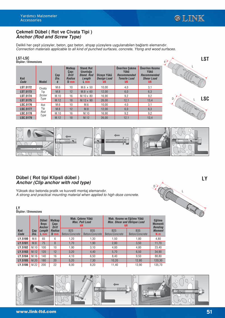
51
Dübel ( Rot tipi Klipsli dübel )Anchor (Clip anchor with rod type)
Yüksek doz betonda pratik ve kuvvetli montaj eleman›d›r.A strong and practical mounting material when applied to high doze concrete.
LY
LYÖlçüler / Dimensions
KodCode
ÇapDia.
M.6M.8M.10M.12M.16M.20M.22
DübelBoyu
AnchorLengthL mm
MatkapÇap›Drill
RadiusD mm
681012162022
LY.5180LY.5181LY.5182LY.5183LY.5184LY.5185LY.5186
Mak. Çekme YüküMax. Pull Load
kN
B35Beton/Concrete
1,301,903,104,406,507,308,20
E¤ilmeMomentiBendingMoment
N.m
4,8011,7023,4034,9088,80120,30135,70
Mak. Kesme ve E¤ilme YüküMax. Shear and Oblique Load
kN
6575100120140180200
B25Beton/Concrete
1,201,701,903,204,105,206,00
B35Beton/Concrete
1,803,504,806,509,5012,8013,90
B25Beton/Concrete
1,502,804,005,708,4010,2011,40
L
D
Çekmeli Dübel ( Rot ve Civata Tipi )Anchor (Rod and Screw Type)
Delikli her çeflit yüzeyler, beton, gaz beton, ahflap yüzeylere uygulanabilen ba¤lant› eleman›d›r.Connection materials applicable to all kind of punched surfaces, concrete, Ytong and wood surfaces.
LST
LSC
L
d
LD
LST-LSCÖlçüler / Dimensions
KodCode
ÇapDia.
d
M.6M.8M.10M.12M.6M.8M.10M.12
Stand.RotUzunlu¤u
Stand. RodLengthL mm
10,0012,0016,9026,0010,0012,0016,9026,00
Dizayn YüküDesign Load
kN
MatkapÇap›Drill
Radius D mm
1012161810121618
Model
CivataTip
ScrewType
RotTipRodType
M.6M.8M.10M.12
M.6M.8M.10M.12
xxxx
50608090
LST.5172LST.5173LST.5174LST.5175LSC.5176LSC.5177LSC.5178LSC.5179
4,06,09,212,14,06,09,212,1
Önerilen ÇekmeYükü
RecommendedTensile Load
kN
3,16,39,213,43,16,39,213,4
Önerilen KesmeYükü
RecommendedShear Load
kN
Yard›mc› MalzemelerAccessories
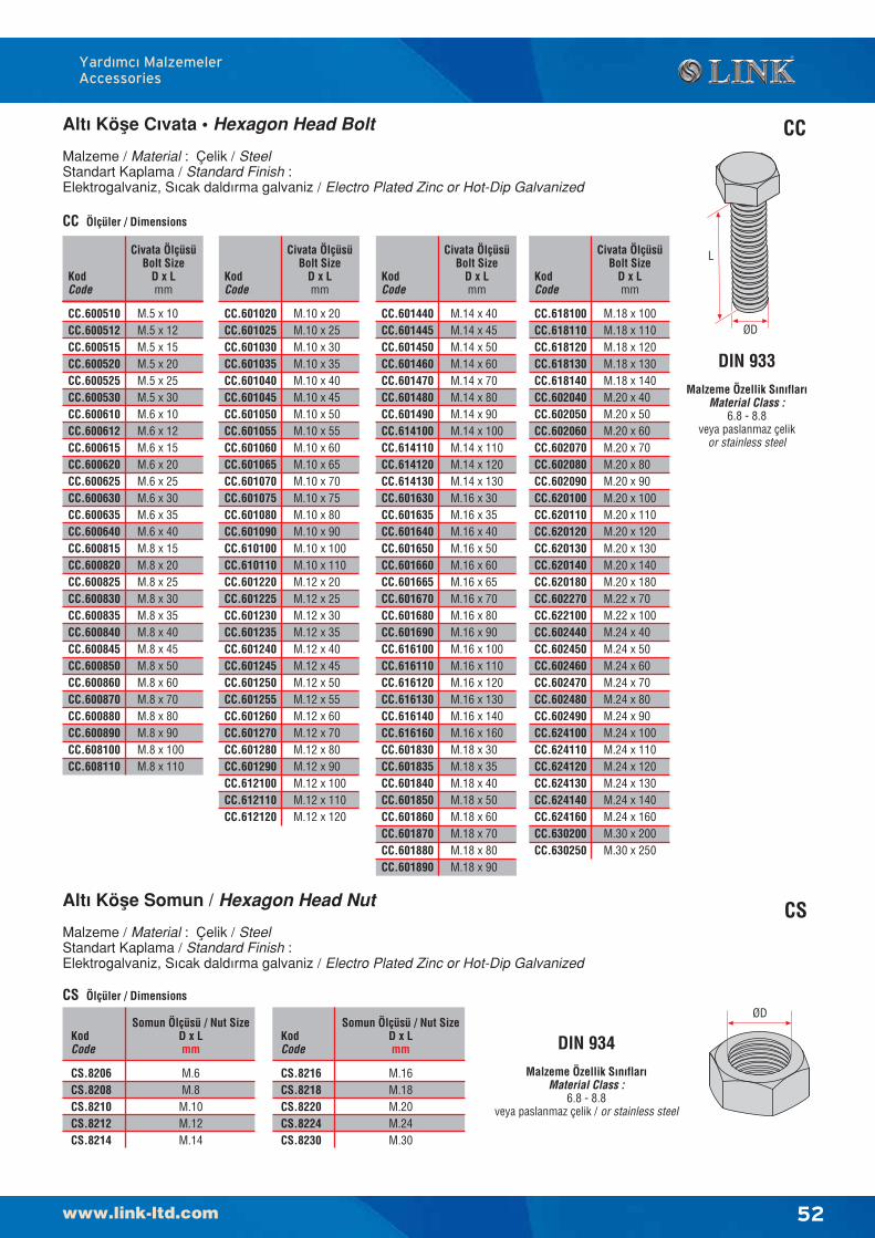
52
Yard›mc› MalzemelerAccessories
Alt› Köfle C›vata • Hexagon Head Bolt
Malzeme / Material : Çelik / SteelStandart Kaplama / Standard Finish :Elektrogalvaniz, S›cak dald›rma galvaniz / Electro Plated Zinc or Hot-Dip Galvanized
CC
ØD
L
DIN 933Malzeme Özellik S›n›flar›
Material Class :6.8 - 8.8
veya paslanmaz çelikor stainless steel
Alt› Köfle Somun / Hexagon Head Nut
Malzeme / Material : Çelik / SteelStandart Kaplama / Standard Finish :Elektrogalvaniz, S›cak dald›rma galvaniz / Electro Plated Zinc or Hot-Dip Galvanized
DIN 934Malzeme Özellik S›n›flar›
Material Class :6.8 - 8.8
veya paslanmaz çelik / or stainless steel
CC Ölçüler / Dimensions
KodCode
Civata ÖlçüsüBolt Size
D x Lmm
M.5 x 10M.5 x 12M.5 x 15M.5 x 20M.5 x 25M.5 x 30M.6 x 10M.6 x 12M.6 x 15M.6 x 20M.6 x 25M.6 x 30M.6 x 35M.6 x 40M.8 x 15M.8 x 20M.8 x 25M.8 x 30M.8 x 35M.8 x 40M.8 x 45M.8 x 50M.8 x 60M.8 x 70M.8 x 80M.8 x 90M.8 x 100M.8 x 110
CC.600510CC.600512CC.600515CC.600520CC.600525CC.600530CC.600610CC.600612CC.600615CC.600620CC.600625CC.600630CC.600635CC.600640CC.600815CC.600820CC.600825CC.600830CC.600835CC.600840CC.600845CC.600850CC.600860CC.600870CC.600880CC.600890CC.608100CC.608110
KodCode
Civata ÖlçüsüBolt Size
D x Lmm
M.10 x 20M.10 x 25M.10 x 30M.10 x 35M.10 x 40M.10 x 45M.10 x 50M.10 x 55M.10 x 60M.10 x 65M.10 x 70M.10 x 75M.10 x 80M.10 x 90M.10 x 100M.10 x 110M.12 x 20M.12 x 25M.12 x 30M.12 x 35M.12 x 40M.12 x 45M.12 x 50M.12 x 55M.12 x 60M.12 x 70M.12 x 80M.12 x 90M.12 x 100M.12 x 110M.12 x 120
CC.601020CC.601025CC.601030CC.601035CC.601040CC.601045CC.601050CC.601055CC.601060CC.601065CC.601070CC.601075CC.601080CC.601090CC.610100CC.610110CC.601220CC.601225CC.601230CC.601235CC.601240CC.601245CC.601250CC.601255CC.601260CC.601270CC.601280CC.601290CC.612100CC.612110CC.612120
KodCode
Civata ÖlçüsüBolt Size
D x Lmm
M.14 x 40M.14 x 45M.14 x 50M.14 x 60M.14 x 70M.14 x 80M.14 x 90M.14 x 100M.14 x 110M.14 x 120M.14 x 130M.16 x 30M.16 x 35M.16 x 40M.16 x 50M.16 x 60M.16 x 65M.16 x 70M.16 x 80M.16 x 90M.16 x 100M.16 x 110M.16 x 120M.16 x 130M.16 x 140M.16 x 160M.18 x 30M.18 x 35M.18 x 40M.18 x 50M.18 x 60M.18 x 70M.18 x 80M.18 x 90
CC.601440CC.601445CC.601450CC.601460CC.601470CC.601480CC.601490CC.614100CC.614110CC.614120CC.614130CC.601630CC.601635CC.601640CC.601650CC.601660CC.601665CC.601670CC.601680CC.601690CC.616100CC.616110CC.616120CC.616130CC.616140CC.616160CC.601830CC.601835CC.601840CC.601850CC.601860CC.601870CC.601880CC.601890
KodCode
Civata ÖlçüsüBolt Size
D x Lmm
M.18 x 100M.18 x 110M.18 x 120M.18 x 130M.18 x 140M.20 x 40M.20 x 50M.20 x 60M.20 x 70M.20 x 80M.20 x 90M.20 x 100M.20 x 110M.20 x 120M.20 x 130M.20 x 140M.20 x 180M.22 x 70M.22 x 100M.24 x 40M.24 x 50M.24 x 60M.24 x 70M.24 x 80M.24 x 90M.24 x 100M.24 x 110M.24 x 120M.24 x 130M.24 x 140M.24 x 160M.30 x 200M.30 x 250
CC.618100CC.618110CC.618120CC.618130CC.618140CC.602040CC.602050CC.602060CC.602070CC.602080CC.602090CC.620100CC.620110CC.620120CC.620130CC.620140CC.620180CC.602270CC.622100CC.602440CC.602450CC.602460CC.602470CC.602480CC.602490CC.624100CC.624110CC.624120CC.624130CC.624140CC.624160CC.630200CC.630250
CS
ØD
KodCode
Somun Ölçüsü / Nut SizeD x Lmm
M.6M.8M.10M.12M.14
CS.8206CS.8208CS.8210CS.8212CS.8214
KodCode
Somun Ölçüsü / Nut SizeD x Lmm
M.16M.18M.20M.24M.30
CS.8216CS.8218CS.8220CS.8224CS.8230
CS Ölçüler / Dimensions
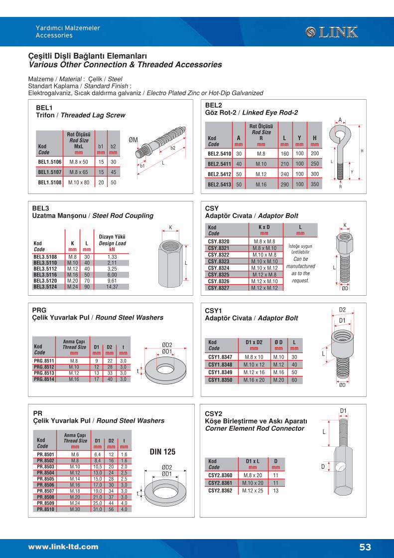
53
Yard›mc› MalzemelerAccessories
Çeflitli Diflli Ba¤lant› Elemanlar›Various Other Connection & Threaded Accessories
Malzeme / Material : Çelik / SteelStandart Kaplama / Standard Finish :Elektrogalvaniz, S›cak dald›rma galvaniz / Electro Plated Zinc or Hot-Dip Galvanized
BEL3Uzatma Manflonu / Steel Rod Coupling
KodCode
Lmm
KmmM.8M.10M.12M.16M.20M.24
304040507090
Dizayn YüküDesign Load
kN1,332,113,256,009,6114,37
BEL3.5108BEL3.5110BEL3.5112BEL3.5116BEL3.5120BEL3.5124
K
L
CSYAdaptör C›vata / Adaptor Bolt
KodCode
K x Dmm
M.8 x M.8M.8 x M.10M.10 x M.8M.10 x M.10M.10 x M.12M.12 x M.8M.12 x M.10M.12 x M.12
Lmm
‹ste¤e uygunüretilebilir
Can bemanufactured
as to therequest.
CSY.8320CSY.8321CSY.8322CSY.8323CSY.8324CSY.8325CSY.8326CSY.8327
BEL1Trifon / Threaded Lag Screw
KodCode
b1mm
Rot ÖlçüsüRod Size
MxLmm
M.8 x 50
M.8 x 65
M.10 x 80
15
15
20
b2mm
30
45
50
BEL1.5106
BEL1.5107
BEL1.5108
b2
b1L
ØM
BEL2Göz Rot-2 / Linked Eye Rod-2
KodCode
Lmm
Rot ÖlçüsüRod Size
Rmm
M.8
M.10
M.12
M.16
160
210
240
290
Ymm
100
100
100
100
Hmm
200
250
300
350
Amm
30
40
50
50
BEL2.5410
BEL2.5411
BEL2.5412
BEL2.5413
L
H
Y
A
R
CSY1Adaptör Civata / Adaptor Bolt
KodCode
D1 x D2mm
M.8 x 10M.10 x 12M.12 x 16M.16 x 20
Lmm
30405060
CSY1.8347CSY1.8348CSY1.8349CSY1.8350
D2
Ø Dmm
M.10M.12M.16M.20
PRGÇelik Yuvarlak Pul / Round Steel Washers
t
ØD1ØD2Kod
Code
Anma Çap›Thread Size
mmM.8M.10M.12M.16
D1mm
9121317
D2mm22283340
tmm3,03,03,03,0
PRG.8511PRG.8512PRG.8513PRG.8514
PRÇelik Yuvarlak Pul / Round Steel Washers
t
ØD1ØD2
DIN 125
KodCode
Anma Çap›Thread Size
mmM.6M.8M.10M.12M.14M.16M.18M.20M.24M.30
D1mm6,48,410,513,015,017,019,021,025,031,0
D2mm12162024283034374456
tmm1,61.62,02,52.53,03,03.04,04.0
PR.8501PR.8502PR.8503PR.8504PR.8505PR.8506PR.8507PR.8508PR.8509PR.8510
L
K
ØD
L
D1
ØD
CSY2Köfle Birlefltirme ve Ask› Aparat›Corner Element Rod Connector
KodCode
D1 x Lmm
M.8 x 20M.10 x 20M.12 x 25
Dmm
111113
CSY2.8360CSY2.8361CSY2.8362
D1
D
L
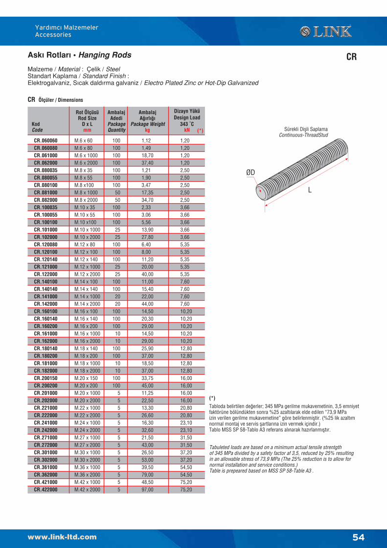
54
Yard›mc› MalzemelerAccessories
Ask› Rotlar› • Hanging Rods
Malzeme / Material : Çelik / SteelStandart Kaplama / Standard Finish :Elektrogalvaniz, S›cak dald›rma galvaniz / Electro Plated Zinc or Hot-Dip Galvanized
CR
CR Ölçüler / Dimensions
KodCode
Rot ÖlçüsüRod Size
D x Lmm
AmbalajAdedi
PackageQuantity
M.6 x 60M.6 x 80M.6 x 1000M.6 x 2000M.8 x 35M.8 x 55M.8 x100M.8 x 1000M.8 x 2000M.10 x 35M.10 x 55M.10 x100M.10 x 1000M.10 x 2000M.12 x 80M.12 x 100M.12 x 140M.12 x 1000M.12 x 2000M.14 x 100M.14 x 140M.14 x 1000M.14 x 2000M.16 x 100M.16 x 140M.16 x 200M.16 x 1000M.16 x 2000M.18 x 140M.18 x 200M.18 x 1000M.18 x 2000M.20 x 150M.20 x 200M.20 x 1000M.20 x 2000M.22 x 1000M.22 x 2000M.24 x 1000M.24 x 2000M.27 x 1000M.27 x 2000M.30 x 1000M.30 x 2000M.36 x 1000M.36 x 2000M.42 x 1000M.42 x 2000
1001001001001001001005050
1001001002525
1001001002525
1001002020
1001001001010
1001001010
100100
55555555555555
CR.060060CR.060080CR.061000CR.062000CR.080035CR.080055CR.080100CR.081000CR.082000CR.100035CR.100055CR.100100CR.101000CR.102000CR.120080CR.120100CR.120140CR.121000CR.122000CR.140100CR.140140CR.141000CR.142000CR.160100CR.160140CR.160200CR.161000CR.162000CR.180140CR.180200CR.181000CR.182000CR.200150CR.200200CR.201000CR.202000CR.221000CR.222000CR.241000CR.242000CR.271000CR.272000CR.301000CR.302000CR.361000CR.362000CR.421000CR.422000
AmbalajA¤›rl›¤›
Package Weightkg
1,121,4918,7037,401,211,903,4717,3534,702,333,065,5613,9027,806,408,0011,2020,0040,0011,0015,4022,0044,0014,5020,3029,0014,5029,0025,9037,0018,5037,0033,7545,0011,2522,5013,3026,6016,3032,6021,5043,0026,5053,0039,5079,0048,5097,00
Dizayn YüküDesign Load
343 ˚CkN
1,201,201,201,202,502,502,502,502,503,663,663,663,663,665,355,355,355,355,357,607,607,607,6010,2010,2010,2010,2010,2012,8012,8012,8012,8016,0016,0016,0016,0020,8020,8023,1023,1031,5031,5037,2037,2054,5054,5075,2075,20
Sürekli Diflli SaplamaContinuous-ThreadStud
ØD
L
(*)
Tabloda belirtilen de¤erler; 345 MPa gerilme mukavemetinin, 3,5 emniyetfaktörüne bölündükten sonra %25 azalt›larak elde edilen “73,9 MPaizin verilen gerilme mukavemetine” göre belirlenmifltir. (%25 lik azalt›mnormal montaj ve servis flartlar›na izin vermek içindir.)Tablo MSS SP 58-Tablo A3 referans al›narak haz›rlanm›flt›r.
Tabuleted loads are based on a minimum actual tensile strentgthof 345 MPa divided by a safety factor af 3,5, reduced by 25% resultingin an allowable stress of 73,9 MPa (The 25% reduction is to allow fornormal installation and service conditions.)Table is prepeared based on MSS SP 58-Table A3 .
(*)
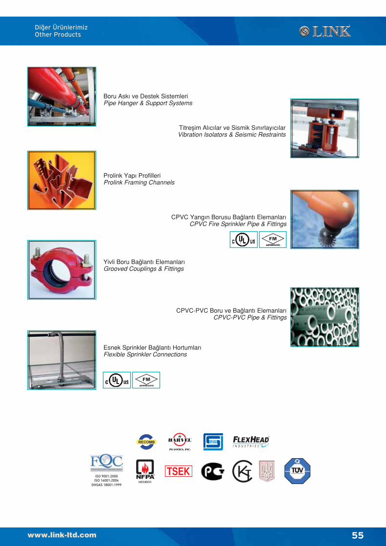
55
Di¤er ÜrünlerimizOther Products
Boru Ask› ve Destek SistemleriPipe Hanger & Support Systems
Prolink Yap› ProfilleriProlink Framing Channels
Yivli Boru Ba¤lant› Elemanlar›Grooved Couplings & Fittings
Esnek Sprinkler Ba¤lant› Hortumlar›Flexible Sprinkler Connections
Titreflim Al›c›lar ve Sismik S›n›rlay›c›larVibration Isolators & Seismic Restraints
CPVC-PVC Boru ve Ba¤lant› Elemanlar›CPVC-PVC Pipe & Fittings
CPVC Yang›n Borusu Ba¤lant› Elemanlar›CPVC Fire Sprinkler Pipe & Fittings
56
Bu sayfa bilinçli olarak bofl b›rak›lm›flt›r.This pages intentionally left blank