1 FLASHING LIQUID EXPANDERS FOR LNG LIQUEFACTION TRAINS Kevin Kaupert Lance Hays Energent Corporation Satish Gandhi Carlos Kaehler ConocoPhillips Company ABSTRACT This paper reports on an axial impulse style of flashing liquid expander that has been designed for the high pressure LNG flash in the ConocoPhillips Optimized Cascade ® process. The flashing liquid expander produces about 2 MW of electric power from the flashing LNG. Removal of this energy from the process increased the amount of LNG leaving the flash by about 3%. Experience with axial impulse expanders in flashing hydrocarbon liquids is reported. The consequences of using conventional radial inflow expanders with flashing liquid flows are also referenced in this paper. Test results and numerical predictions are presented for a scale model axial impulse expander using flashing liquid nitrogen. INTRODUCTION Improvement of the efficiency in LNG liquefaction processes by replacement of the liquid flow Joule- Thomson (“J-T”) valves with liquid expanders is now standard practice in LNG liquefaction trains. The expanders for these liquid flow LNG liquefaction trains are based on conventional well established radial inflow centrifugal expander technology which cannot tolerate flashing liquid flow with high vapor fractions. The formation of flashing flow in radial inflow expanders is documented to result in performance losses [e.g., Gülich 1981, 2001 & Apfelbacher et al. 1989]. Radial inflow turbines are also known to suffer from erosion on the blades by high velocity liquid droplet impact when handling flashing flow [e.g., Schuller 2011]. The ConocoPhillips Optimized Cascade ® LNG Process has several flashing liquid J-T valves which are different than the above mentioned liquid only J-T valves. Replacement of these flashing liquid J-T valves with flashing liquid expanders can increase the LNG liquefaction train output by 2-5%. However, the several flashes in this process would all result in flashing liquid flow inside any conventional radial inflow expander which is not acceptable. ConocoPhillips commissioned an engineering design study with Energent to investigate the use of axial impulse style expanders in flashing LNG. Axial impulse units have been successfully applied to commercial refrigeration systems where the flashing vapor to liquid volume ratios within the expander has reached up to 95% vapor volume fraction [Hays & Brasz 1998]. Axial impulse style units have also been successfully applied to oil and gas flashing flows and high temperature geothermal flashing flows [Hays 1999]. [® Optimized Cascade is a registered trademark of ConocoPhillips Company in the United States.]
Transcript
1
FLASHING LIQUID EXPANDERS FOR LNG LIQUEFACTION TRAINS
Kevin Kaupert Lance Hays
Energent Corporation
Satish Gandhi Carlos Kaehler
ConocoPhillips Company ABSTRACT
This paper reports on an axial impulse style of flashing liquid expander that has been designed for the high pressure LNG flash in the ConocoPhillips Optimized Cascade® process. The flashing liquid expander produces about 2 MW of electric power from the flashing LNG. Removal of this energy from the process increased the amount of LNG leaving the flash by about 3%.
Experience with axial impulse expanders in flashing hydrocarbon liquids is reported. The consequences of using conventional radial inflow expanders with flashing liquid flows are also referenced in this paper. Test results and numerical predictions are presented for a scale model axial impulse expander using flashing liquid nitrogen.
INTRODUCTION
Improvement of the efficiency in LNG liquefaction processes by replacement of the liquid flow Joule-Thomson (“J-T”) valves with liquid expanders is now standard practice in LNG liquefaction trains. The expanders for these liquid flow LNG liquefaction trains are based on conventional well established radial inflow centrifugal expander technology which cannot tolerate flashing liquid flow with high vapor fractions. The formation of flashing flow in radial inflow expanders is documented to result in performance losses [e.g., Gülich 1981, 2001 & Apfelbacher et al. 1989]. Radial inflow turbines are also known to suffer from erosion on the blades by high velocity liquid droplet impact when handling flashing flow [e.g., Schuller 2011].
The ConocoPhillips Optimized Cascade® LNG Process has several flashing liquid J-T valves which are different than the above mentioned liquid only J-T valves. Replacement of these flashing liquid J-T valves with flashing liquid expanders can increase the LNG liquefaction train output by 2-5%. However, the several flashes in this process would all result in flashing liquid flow inside any conventional radial inflow expander which is not acceptable.
ConocoPhillips commissioned an engineering design study with Energent to investigate the use of axial impulse style expanders in flashing LNG. Axial impulse units have been successfully applied to commercial refrigeration systems where the flashing vapor to liquid volume ratios within the expander has reached up to 95% vapor volume fraction [Hays & Brasz 1998]. Axial impulse style units have also been successfully applied to oil and gas flashing flows and high temperature geothermal flashing flows [Hays 1999].
[® Optimized Cascade is a registered trademark of ConocoPhillips Company in the United States.]
2
HISTORICAL DEVELOPMENT OF FLASHING LIQUID EXPANDERS
The most obvious path for the development of a flashing liquid expander is to try and adapt existing thermal and hydraulic expanders to handle a flashing liquid. This was attempted initially by NASA in the 1960s using radial inflow centrifugal expanders with unsatisfactory results in terms of efficiency and vibrations. Later in the 1980s several companies again tried the radial inflow centrifugal expander for handling flashing liquids [Gülich 1981 & 2010, Apfelbacher et al. 1989]. Again they found poor efficiency as the vapor volume fraction throughout the expander increased. In the work of Gülich the liquid wasn’t actually flashing, rather air was added to water in controlled measured amounts. The expander was a 3 stage centrifugal pump run in reverse. The work of Gülich showed as the mass vapor fraction reaches 0.002 (a vapor volume fraction of near 30%) the turbine efficiency dropped by more than 20 points. The efficiency degradation is well summarized in the work of Gülich as a function of the vapor volume fraction in the liquid. In the work of Apfelbacher an 8 stage centrifugal pump was run in reverse and a hydrocarbon mixture was flashing through the machine. The expander outlet fluid had 35% vapor volume. The work of Apfelbacher measured an efficiency 5 points lower than found with a single phase non-flashing liquid.
Due to the documented performance deteriorations the radial inflow centrifugal expander was abandoned by the turbomachinery community for use with flashing liquids. It was correctly reasoned that the centrifugal field, which is the functioning basis for radial inflow expanders, acts as a centrifugal separator between liquid and vapor and hence leads to poor efficiency as the vapor volume fraction increases at the impeller inlet. In effect an upper limit of near 0 is set on the amount of vapor that can be flashed before the flow enters the centrifugal impeller. From a design perspective this can be reviewed in the example P vs h diagram of Figure 1. [Ed. note: Figures appear at the end of the text, beginning with page 6.] In the example, a degree of reaction of 0.5 is assumed for the centrifugal expander although this could easily be lower for more enthalpy drop in the nozzles. Vapor will form (52% vapor volume) at the nozzle outlet before the impeller adversely impacting efficiency and vibrations of the unit. This result is due to the centrifugal separator effect as the vapor and liquid have different densities and the radial pressure gradient acts on each phase with dP/dr= ρVθ
2/r where P is the pressure, r is the radius, ρ is the density, and Vθ is the tangential velocity. Taking a simple example in LNG, letting Vθ=100m/s, r=0.2m, and for the vapor ρv=3 kg/m3 gives (dP/dr)v=150 kPa/m while for a liquid with ρl=350 kg/m3, we have (dP/dr)l=17 500 kPa/m. The ratio between these vapor and liquid centrifugal fields is,
(dP/dr)l / (dP/dr)v = ρl / ρv =350 / 3 =116.67
This large difference in the centrifugal field discourages the use of radial inflow centrifugal style turbomachines for flashing flows since the centrifugal field strongly separates the phases in the liquid-vapor mixture. In fact, it is this centrifugal effect that is advantageously used to separate such liquid-vapor mixtures in commercial centrifugal separators in the oil & gas industries.
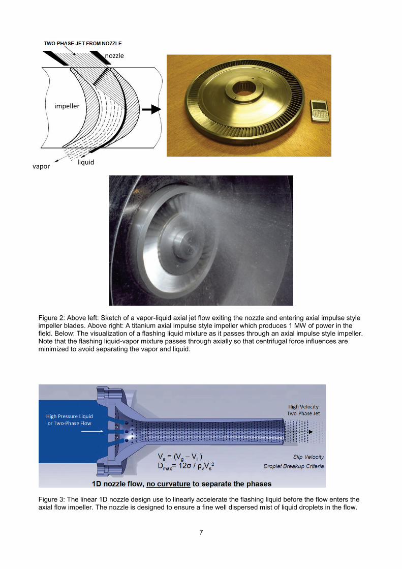
The poor performance and high vibrations caused by flashing liquids in radial inflow centrifugal expanders were motivation for NASA and the Jet Propulsion Laboratory (JPL) to embark on a program to develop a new means of expanding flashing liquids. The driving application was a magnetohydrodynamic power system project [Elliott et al., 1966 & 1968]. The flashing liquid expander methodology applied at JPL was a linear nozzle expansion of the flashing liquid flow, avoiding curvature and ensuring close coupling between the expanding vapor and liquid droplets. This method proved successful, producing a good conversion of the available enthalpy drop to nozzle outlet kinetic energy. The successful nozzle design was applied to an axial impulse expander impeller. The new style of expander seen in Figure 2 [Elliott 1982] was an axial impulse style expander, similar to an axial cross-flow expander or even similar to a Pelton style impulse turbine.
3
AXIAL IMPULSE EXPANDER
An axial impulse expander design that uses linear nozzles to flash a liquid to vapor has the advantages of:
1. Avoiding a centrifugal field that acts counter to the main flow direction and separates the flashing liquid and vapor phases,
2. A zero reaction (impulse expander) so there is no enthalpy (pressure) change in the impeller, only the conversion of flow kinetic energy to shaft power, and
3. No curvature of the flashing flow in the nozzles which again avoids separating the phases.
An example of a linear nozzle is seen in Figure 3. In the axial impulse style expander the inlet liquid undergoes a controlled linear expansion in the nozzle to form a flashing liquid and vapor mixture. The controlled expansion forms a fine mist of droplets which has a low slip velocity and hence high efficiency nozzle. These findings were verified by NASA, JPL, and Caltech by experimental testing and development [Elliott 1982]. In the axial impulse expander the impeller is an impulse style so there is no pressure or enthalpy drop across the impeller, only across the nozzles. The impeller can be manufactured from hard, light weight titanium which together with impact velocities being well below the erosion threshold, eliminates any erosion that droplet impact could cause. Titanium impellers are commonplace in the turboexpander industry with a long history of operational success.
EXISTING AXIAL IMPULSE EXPANDER DESIGNS
Over 100 axial impulse style flashing liquid expanders have been in service for 30 years. They are found for example in refrigeration chillers [Hays & Brasz 1998]. The power levels in these chillers are however only in the range of 20 kW to 55 kW. Larger axial impulse style flashing liquid expanders are found operating in geothermal applications including units at 800kW and 1.6 MW power levels [Hays 1999]. Some 10 other axial impulse style expanders for flashing liquids are found in the oil & gas industry in the size range from 20 kW to 100 kW [Hays 1999]. From a new construction point of view, Figure 4a and Figure 4b show a new 1.0 MW axial impulse expander for a flashing hydrocarbon liquid application that was recently commissioned. The design features an axial impulse style impeller with ten nozzles to flash a liquid hydrocarbon. The generator is of the external air cooled type. The single stage design keeps the unit axially compact to ensure stable rotor dynamics and low vibrations.
AXIAL IMPULSE EXPANDERS FOR LNG
A flashing liquid expander has been designed for the high pressure LNG flash in the ConocoPhillips Optimized Cascade® process [Hays & Welch 2011]. The expander design produces 2 MW of electric power from the flashing LNG and is of the submerged generator type. Removal of this energy from the process increases the amount of liquid LNG leaving the flash by about 3% [Hahn et al. 2007].
The flashing liquid expander designed is shown in the solid model of Figure 5. It has not yet been manufactured. High pressure LNG liquid or flashing liquid enters the inlet flange, 1, filling a plenum. The LNG enters the flashing liquid nozzles, 2, wherein the flashing is a near isentropic expansion. The resulting flashing flow in the nozzle jets drive an axial impulse impeller, 3, turning the impeller at the generator synchronous speed. The low pressure combined liquid and vapor LNG stream leaves the impeller, and exits 4, in the axial downward direction. The impeller drives a shaft, 12, supported by deep groove anti friction ball bearings, 8 and 11. The induction generator rotor, 13, is mounted on the shaft. The rotation of the generator rotor produces power in the stator, 14, which is removed from the assembly and the process through a high voltage hermetic feed through (not shown) of the type commonly used in submerged LNG pumps.
With regard to cooling the generator and balancing the axial thrust, a side stream of LNG is introduced to the assembly through a port, 5. The LNG flows, 6, to the upper end of the assembly between the generator support and the containment casing. At the upper end the LNG reverses direction and flows through a hole,
4
7, into the gap between the rotor and stator, providing generator cooling. The LNG also flows through the upper bearing, 8, providing cooling for the bearing. After leaving the bearing the LNG flows through a balance piston, 9, providing lift on the turbine–generator rotating assembly. The balance piston provides lift and the LNG flow rate is controlled by a variable orifice, 10, that moves axially until the axial thrust is totally balanced. The balance piston design is similar to that used on submerged LNG pumps, of which hundreds have been successfully deployed and are operating. After throttling, the LNG flows through a return line to rejoin the main flow. The flow through the generator rotor-stator gap flows through the lower bearing, 11, and leaves through a port, 15, to be rejoined with the main flow.
The expander assembly shown is hermetic with no external rotating seals. The mechanical design is similar to that found in submerged LNG pumps, but simpler due to the single stage impulse impeller as contrasted to a multistage pump rotor. The hermetic generator design is simpler than an external generator design in that it eliminates the need for a lube oil system, dry gas seals, and seal gas support system. Furthermore, the hermetic generator has the advantage of size reduction compared to an external generator. However, it must also be mentioned that the hermetic generator has the disadvantage of heat input into the cryogenic fluid due to generator inefficiency as well as windage losses of the generator rotating in a liquid as opposed to an external generator rotating in air. Another limitation on the submerged style generator is the power output which is limited to roughly 3 MW. This is not due to any technical limitation but rather by current manufacturing methods and tooling available for construction. So in general if the power output of the generator is to exceed 3 MW then the design will require an external style generator.
TEST RESULTS IN LN2
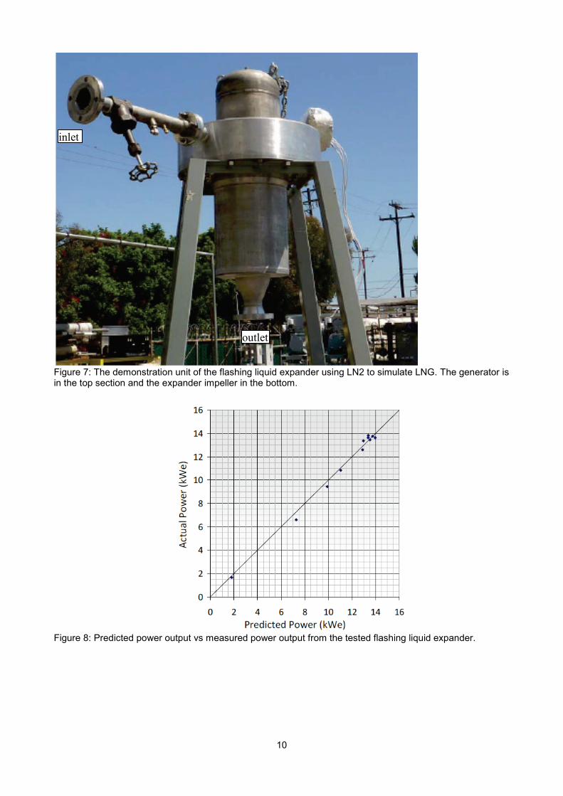
A set of qualification tests were made in a cryogenic environment for LNG with a hermetic sealed flashing liquid expander using a submerged generator. The prototype was designed with four flashing liquid nozzles. Liquid nitrogen was used at the Energent test facility, pressurized to a condition of 15 bar and -164 °C. The maximum flow rate at this pressure was 6.8 kg/s. The liquid nitrogen was flashed through the flashing liquid expander to a pressure of 1.5 bar and -192 °C. At the exit the vapor quality was 21%. At the pressure and temperature conditions of the high pressure tank and at the maximum flow rate, the predicted power was 14 kW. Figure 6 is a picture of the axial impeller during machining. The blade profiles are designed to minimize losses from impinging liquid. The material of construction for the prototype unit rotor was aluminum. The full size LNG impeller will be constructed from titanium alloy. The demonstration unit is shown in Figure 7. The unit is oriented such that the submerged generator is on top with a downward discharge of the flashing liquid flow. This is to ensure that heavier liquid falls with gravity and that lighter vapor buffers the impeller to reduce windage losses on the rotating impeller. Operation of the expander was smooth with low vibrations less than 1 mm/s as measured near the bearing, and performance was controlled with an inlet control globe valve. A variable frequency drive was used to vary the impeller speed. The turbine was operated with saturated liquid nitrogen and with flashing liquid flow at the inlet that contained up to 100% vapor quality at the expander inlet. This operation with flashing flow at the expander inlet demonstrated the expander’s ability to operate with process cases that contain vapor in the flashing liquid as well as during plant upsets without damage or tripping of the expander.
Figure 8 is a graph of the measured power versus predicted using numerical codes that Energent has developed specifically for flashing liquid expander design. The numerical code includes modeling of both the nozzles and the impeller flow fields. These codes require the use of supersonic compressible flow relations since the speed of sound in a flow falls rapidly as a liquid begins to flash with vapor formation. The data for the graph were taken for a range of inlet vapor quality from 18% to 0%. Inlet temperature ranged from -164 °C to -174 °C. Inlet pressure ranged from 6 bar to 13 bar. Exhaust pressure was 1.3 to 1.9 bar. Flow rate was 4 660 kg/hr to 11 930 kg/hr. As can be seen the measured power agrees reasonably with predicted over the wide range of variables tested and with flashing liquid flow at the expander inlet.
5
CONCLUSIONS
A long history of testing has shown that radial inflow style expanders are less suitable for handling flashing liquid flows, mainly, due to the presence of a strong centrifugal field separating the heavier liquid from the lighter vapor. Contrarily, axial impulse style expanders that avoid the strong centrifugal field have proven themselves in several flashing liquid expander applications such a chiller systems, waste heat recovery, geothermal power generation, and the oil & gas industry. The flashing liquid expander design presented in this paper is a natural extension of these previous designs. It has been successfully tested with both a hermetic generator and an external generator. The numerically predicted power output from the flashing liquid expander agreed reasonably well with that measured on the test stand.
REFERENCES
Apfelbacher, R., Hamkins, C., Jeske, H., & Schuster, O., (1989) Kreiselpumpen in Turbinenbetrieb bei Zweiphasen-Strömungen, KSB Technishe Berichte 26, pp20-28.
Elliott, D.G., Ceromo, D.J., & Weinberg, E., (1966) Liquid-Metal MHD Power Conversion, Space Power Systems Engineering, Academic Press Inc., pp1275-1297.
Elliott, D.G., & Weinberg, E., (1968) Acceleration of Liquid in Two-Phase Nozzles, JPL Publication 32-987, Jet Propulsion Laboratory, Pasadena, California.
Elliott, D.G., (1982) Theory and Tests of Two-Phase Turbines, JPL Publication 81-105 (DOE/ER-10614-1), Jet Propulsion Laboratory, Pasadena, California.
Gülich J., (1981), Energierückgewinnung mit Pumpen in Turbinenbetrieb bei Expansion von Zweiphasengemischen, Sulzer Technical Review, Vol 3, pp87-91.
Gülich J., (2010), Kreiselpumpen: Handbuch für Entwicklung, Anlagenplanung und Betrieb, Springer Verlag, Heidelberg.
Hahn, P., Huang, S., Kaehler, C., Baer, M., Cook, D., Meher-Homji, C., & Ojeda, A., (2007), Application of a Flashing Liquid Expander to Enhance LNG Production, LNG-15 Conference Poster Presentation, Barcelona, April.
Hays, L.G., (1999) History and Overview of Two-Phase Flow Turbines, C542/082/99, IMechE International Conference on Compressors and their Systems, 13-15 September, City University, London, UK, pp159-168.
Hays, L.G., & Brasz. J.J., (1998) Two-Phase Flow Turbines as Stand-Alone Throttle Replacement Units in Large 2000-5000 Ton Centrifugal Chiller Installations, Proceedings of the 1998 International Compressor Engineering Conference, Purdue, USA, Vol II, pp 797-802
Hays, L.G., & Welch, P., (2011) An Axial Flow Hermetic Turbine for Flashing LNG Applications, AICHE Spring Meeting, 11th Topical Conference on Gas Utilization. LNG Equipment and Technology, March 13-17, Chicago, USA.
Schuller, S., (2011) Best Exergy Point for ORC, Geothermal Resources Council (GRC) Conference Transactions, Oct 23-26, San Diego, USA, Vol. 35, pp1343-1350.
6
Example P vs h Diagram for a Single Stage Radial Inflow Centrifugal Turbine Flashing a Hydrocarbon Liquid
T1 T2 T3 T4 T5 T6
Enthalpy
Pres
sure
Nozzle Inlet
Nozzle Outlet
Impeller Inlet
Impeller Outlet
0.00 xv
0.00 φv
0.16 xv
0.52 φv
0.29 xv
0.83 φv
xv = Vapor Mass Fractionφv = Vapor Volume Fraction
Figure 1: Typical P vs h diagram for a single stage radial inflow centrifugal turbine during a liquid to vapor, flashing expansion with a hydrocarbon liquid (degree of reaction conservatively selected was 0.5). Note the presence of vapor at the impeller inlet where the centrifugal field is strongest which separates the mixture like a centrifugal separator.
Nozzle Inlet
Nozzle Outlet / Impeller Inlet
Impeller Outlet
7
Figure 2: Above left: Sketch of a vapor-liquid axial jet flow exiting the nozzle and entering axial impulse style impeller blades. Above right: A titanium axial impulse style impeller which produces 1 MW of power in the field. Below: The visualization of a flashing liquid mixture as it passes through an axial impulse style impeller. Note that the flashing liquid-vapor mixture passes through axially so that centrifugal force influences are minimized to avoid separating the vapor and liquid.
Figure 3: The linear 1D nozzle design use to linearly accelerate the flashing liquid before the flow enters the axial flow impeller. The nozzle is designed to ensure a fine well dispersed mist of liquid droplets in the flow.
vapor liquid
nozzle
impeller
8
Figure 4a: A 1 MW flashing liquid expander system used for geothermal power generation where a hydrocarbon liquid is flashed through the expander.
Figure 4b: Detailed view of the 1 MW flashing liquid expander currently in operation.
expander generator
expander generator
9
Figure 5: A solid model rendering section of the flashing liquid expander designed using a hermetic generator. The numbers are described in the text.
Figure 6: Manufacturing of the axial impeller for the tested flashing liquid expander.
10
Figure 7: The demonstration unit of the flashing liquid expander using LN2 to simulate LNG. The generator is in the top section and the expander impeller in the bottom.
Figure 8: Predicted power output vs measured power output from the tested flashing liquid expander.