LONDON," HIS MAJESTY'S S T A T I O N E R Y O F F i C ~
~95~ P&xc~. 4s 5d N~.'r
' !}7.,; + %:" .?> I~ i+, ,% ~i
The Prevention of Binary Flutter by Damping
By
R . A . FRAZF.R, B.A., D.Sc.,
of the Aerodynamics Division, N .P .L .
Artificial
Reports ancl Memor nd No. 2 5 5 2
x6tA February , i 9 4 4
Summary. - -Range of InvesEgation.--Formulae are obtained which provide an estimate of the amount of artificial control needed to prevent binary flutter. Results are expressed in terms of a 'minimum damping multiplier ' R, defined as the ratio of the least direct damping coefficient required for absolute flutter prevention to the ' n a t u r a l ' direct aerodynamic damping coefficient of the control surface concerned. Numerical results are obtained for five different types of aircraft.
ComIusioas.--The main conclusions are as follows : - - (i) R varies with the type of flutter and increases markedly with l~eight.
(ii) Large values of R are to be expected with high structural density or mass-underbalance of the control surfaces. (iii) Maximum height should (in general) be assumed in the estimation of artificial damping. (iv) With artificial damping of conventional type servo-operated controls and devices for reduction or cut-out of
the damping at low speeds will normally be necessary. (v) If artificial damping is applied to a main control surface, mass-balancing of the servo-flap may be necessary.
1. Introduction and Conclusions.--The theoretical advantages of heavily damped control surfaces from the standpoint of flutter prevention have long been recognized.* Recently it has been suggested that artificial damping might be preferable to mass-balancing as a means of preventing flutter, since weight might be saved. The purpose of the present paper is to provide simple formulae from which the amount of additional damping required can be estimated.
Attention is restricted to binary flutter, which is referred to as being of Class A or B according to the nature of the dynamical coefficients (see Table 1). With Class A two of the aerodynamical stiffness coefficients are zero (cl = c~ -- 0) ; whereas with Class B all the aerodynamic stiffnesses are present. The formulae obtained differ for the two classes of flutter• The detailed proofs, which assume simple classical derivative theory and depend on the properties of test conics,~ are given in the Appendix. In general, the control surfaces considered are assumed to be mass underbalanced.
The damping values obtained are theoretically sufficient for the absolute prevention of flutter (i.e. prevention for all elastic stiffnesses). In practice, increased values should be taken, to allow for uncertain data. For convenience, results are expressed in terms of a minimum damping multiplier R, which is defined as the ratio of the least direct damping coefficient required for absolute flutter prevention to the ' n a t u r a l ' direct aerodynamic damping coefficient of the control surface concerned. The value of R varies with the altitude h owing to the increasing influence of the structural inertias with decreasing air density p.
* See, for example, recommendation (e) of section 9, R. & M. 11551. t See Chapters I I I and VIII of R. & M. 1155 I.
Also Conclusion (d) on p. 1 of R. & IV[. 16852.
(9zoo~) A
In practice, artificial damping proportional t o : p a n d t o airspeed .V, (and thus providing an increase of damping coefficient) is unlikely to be achieved by any simple means. I f the device used provides merely constant additional, damping, the amount of this should be of sufficient magnitude to ensure that at any height h (It), and for the corresponding true maximum diving speed V,, (It/sec) flutter is absent. ~ihe total effective damping coefficient Will then 'be on the safe side for other flight conditior~s. Suppose, for example, that the case considered is flexural- aileron flutter, and let the coefficients* be defined as in Table l(a). Then if R denotes the minimum damping multiplier corresponding to air densi ty p, the constant artificial aileron damping to be supplied is given by
K -- p (R -- 1) V,,}Co'~e~, . . . . . . . . . . . .:~,~,..:.. (1)
where the height should be chosen such that p (R -- 1) V~ has its greatest value. In this case the effective damping multiplier for any other air density p' and for any speed V ' <~ V,,, will be
1 q- pV,,, (R - - 1) p ' V '
which will certainly exceed R' . the minimum multiplier corresponding to air density o'. Numerical examples given in sections 2 and 3 indicate that (in general) maximum height should be assumed in the estimation of K. In the absence of definite information t h e value of V,~ is taken to be independent of the height in the examples.
The quanti ty K in (1) measures the aileron hinge moment (in lb ft) due to artificial damping when the aileron is rotated steadily at a rate of 1 rad/sec.
(a) Damping Formulae for. Class A F lu t t er . - -Th i s class is represented by standard flexural- aileron flutter and by rudder flutter involvil~g fuselage torsion. The formulae, which involve one or both of the moment-of-inertia coefficients as well as the product-of-inertia coefficient p, differ according to the sign of fl (for symbols, see Table l(a)).
Case (i). Flexural-Ai leron Fl~tter (f2 > O, fl > 0). The value of R is here given by tile greatest positive root of the equation
Case (ii). Rudder-torsional Flutfer (f2 > O, ~ < 0).
For (A~) substitute
Condit'ions (A~) and (A~) ensure test conic diagrams of the types Figs. 1(c) and 1 (b) respectively.
(b) Damping Formulae fo r Class B F lu t t er . - -Th i s class includes most other varieties of flutter (e.g. torsional-aileron, servo-rudder, elevator-fuselage, etc.). The formu!ae are independent of the moments of inertia.
Let/zl, ~*a denote the two roots of the equation
~ , ~ - - { e 3 j z + 2 p ( k ~ + f 3 ) } / ~ + p z ( k z - - f a ) 2 + 2 5 / 3 ( j ~ + e a ) = O . . . . . . . (2)
Then if t~l, f~2 are real (,.~ > ~q) the multiplier R to be applied to the product e2j3 of the two natural direct damping coefficients is given by
If [q, Et~ are unreal, choose
R . . . . . . . . . . . . . . . (B1)
R = /32/4ez kJ .
* I f the coefficients used are not non-dimensional, the formulae should be applied with l and c o suppressed.
2
Conditions (B~) and (B~) correspond respectively to test conic diagrams of the types Fig. 2(d), and Fig. 2(b) with T below H,,. W i t h t y p e s of flutter other than those considered in this paper the formulae used should be guided by the geometry of the test diagram.
Numerical results for some representative aircraft and for various types of flutter are sum- marized in Table 2. ~Ihe following conclusions are indicated by the calculations.
General Co ndusions.--(i) The minimum damping multiplier R varies with the type of flutter and increases markedly with height.
(fi) Large values for R are to be expected with high structural density or pronounced mass underbalance of the control surfaces.
(iii) Maximum height should (in general) be assumed in the estimation of the artificial damping K.
(iv) With artificial damping of conventional type, servo-operated controls and devices for reduction or cut-out of the damping at low speeds will normally be necessary.
(v) If artificial damping is applied to a main control surface, mass-balancing of the servo-flap may be unnecessary.
I t is considered probable that an aileron which is adequately damped to prevent flexural- aileron and torsional-aileron flutter, will also prove to be adequately damped against ternary flutter and tab-aileron flutter. However, a verification of this conjecture by calculation would be desirable before altificial damping were tried out in practice.
2. Numerical Examples (Class A Flutter).--(i) Flexural-Aileron Fh#ter (Fighter Aircraft).-- The data are taken from the end of section 2, R. & M. 2551 a, and relate to a fighter aircraft (aircraft S of Ref. 5). ~fhe dimensions, in feet, for full-scale are
Co (ro0t-chord of wing) = 5.87 s (span Of one wing) = 18.5 G (aileron mean chord) = 1.38 s~ (aileron span) = 6-85 1 = 0.57s = 10.54
Aerodynamic Coefficients (non-dimensional, Table 1 (a) ) bl -- 5.78, el = 0.298, f l = 1.39, b~ = 0-00972, e2 = 0.009225, f2 = 0. 0146.
Aero@namw Dwrtial Coefficients (non-dimensional) Po =: 0.0162, d2o = 0"00054.
Total Inertial Coefficients (Structural plus Aerodynamic)
dtitude (ft) . . . . .
o/p . . . . . .
"abric aileron covering
duminium aileron covering
P d~
p d~
0
1-0
0-0998 0.00587
0.325 0.0202
10,000
1 '35
0.128 0'00773
0"433 0.0271
20,000
1 "88
0"173 0'0105
0'597 0'0376
30,000
2"67
.0"239 0.0148
0"841 0"0531
40,000
4"06
0"356 0"0222
1 "27 0"0805
3 (93004) .A. 2
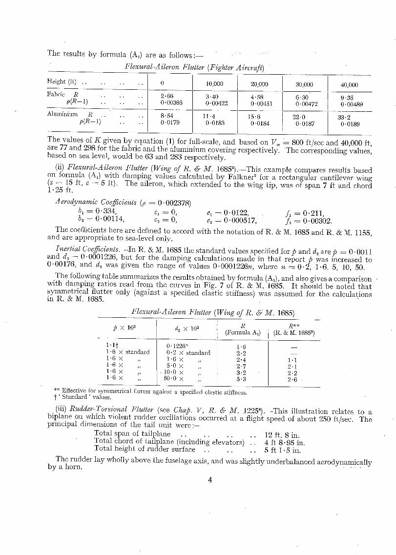
The results by fornmla (A,) are as follows : ~ . . . . . '
Flexural-A ileron Flu#er (Fighter Aircraft)
H e i g h t (ft) . . . .
F a b r i c R . . . . . . p ( R - - 1 ) . . . . . .
A l u m i n i u m R . . . . . . p ( R - - 1 ) . . . .
0
2 . 6 6 0 .00395
8 ' 5 4 0 .0179
10,000
3"40 0"00422
11"4 0 .0183
20,000
4"58 0"00451
15"6 0"0184
30,000
6- 30 O- 00472
2 2 . 0 0 -0187
40,000
9"35 O. 00489
33"2 0"0189
The values of K given by equat ion (1) for full-scale, and based on V,,, = 800 ft/sec and 40,000 ft, are 77 and 298 for the fabric and the a luminium covering respectively. T h e corresponding values, based on sea level, would be 63 and 283 respectively.
(it) Flexural-Aileron Flutter (Wing of R. & M. 1685=).--This example compares results based on formula (A,) with damping values calculated by Falkner ~ for a rectangular canti lever wing (s = 15 ft, c = 5 ft). The aileron, which ex tended to the wing tip, was of span 7 It and chord 1.25 ft.
Aerody~camic Coefficients (p = 0"002378)
bl = 0" 334, cl = 0, el = 0" 0122, f l -- 0" 211, b2 = 0"00114, c2 = 0, & = 0"000517, f2 = 0"00302.
The coefficients here are defined to accord with the nota t ion of R. & M. 1685 and R. & M. 1155, and are appropriate to sea-level only.
Inertial Coefficients.--In R. & N. 1685 the s tandard Values specified for 15 and & are p = 0.0011 and d.., = 0"0001226, but for the damping calculations made in tha t r epor t p was increased to 0.00176, and d~ was given the range of values 0"0001226n, where n = 0.2, 1.6. 5, 10, 50.
The following table summarizes the results obta ined by formula (A~), and also gives a comparison - with damping ratios read from the curves in Fig. 7 of R. & M. 1685. I t should be noted tha t symmetr ical flutter only (against a specified elastic stiffness) was assumed for the calculations in R . & M. 1685.
Flexural-Ailero~ Flutter (Wi%e of R. ~' M. 1685)
p X 10 a d~ × 10 a
0 .1226~ 0 . 2 × s t a n d a r d 1 . 6 × ,, 5"0 × ,,
. 1 0 . 0 × ,, 5 0 . 0 × ,,
R ( F o r m u l a A1)
1 .6 2 . 2 2 . 4 2 . 7 3 . 2 5 . 3
1.1 t 1 .6 × s t a n d a r d 1 .6 x ,, 1 .6 × ,, 1 .6 × 1 .6 x ,,
R** (R. & M. 1685 a)
1"1 2"1 2"2 2"6
** Ef fec t ive for s y m m e t r i c a l f lu t te r agains t a specif ied e las t ic stiffness. ' S t a n d a r d ' values .
(iii) Rudder-Torsional Flutter (see Chap. V, R. & M. 12254).--This il lustration relates to a biplane on which violent rudder oscillations occurred a t a flight speed of about 250 ft/sec. The principal dimensions of the tail uni t Were : -
Total span of tailplane . . 12 ft. 8 in. Total chord of tai lplane (including elevators) .. 4 ft 8 .95 in. Total height of rudder surface . . . . . . 5 It 1.5 in.
The rudder lay wholly above the fuselage axis, and was slightly underbalanced aerodynamical ly by a horn. -
4
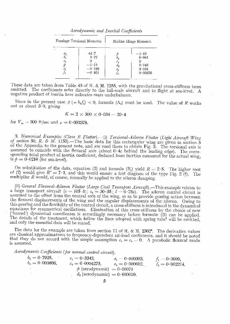
Aerodynamic and Inertial Coefficients
Fuselage Torsional Moments Rudder Hinge Moments
bl C 1
C 1
fi
44"7 1"77 0
--1.15 --0.186 --0'101
b2 Ca
4 g2
A
--1.15 0-041 0 0.745 0.034 0.00358
These data are taken from Table 43 of R. & M. 1255, with the gravitational cross-stiffness term omitted. The coefficients refer directly to the full-scale aircraft and to flight at sea-level. A negative product of inertia here indicates mass underbalance.
Since in the present case /~ ( =- b~f~) < 0, formula (A~) must be used. The value of R works out as about 3.0, giving
K - - 2 × 300 × 0 . 0 3 4 - - 2 0 . 4
for V,,, = 300 ft/sec and p =- 0.002378.
3. Numerical Examples (Class B Flutter).--(i) Torsional-Aileron Flutter (Light Aircraft Wing of section 50, R. & M. 1155).--The basic data for this rectangular wing are given in section 5 of the Appendix to the present note, and are used there to obtain Fig. 3. The torsional axis is assumed to coincide with the ftexural axis {about 0.4c behind the leading edge). ~he corre- .sponding total product of inertia coefficient, deduced from inertias measured for the actual wing, as/5 = 0.0216 (for sea-level).
On substitutioii of the data, equation (2) and formula (B1) yield R = 2.5. The higher root of (2) would give R' = 7 . t , and this would ensure a test diagram of the type Fig. 2 (f). The multiplier R would, of course, normally be applied to the aileron damping.
(ii) General Flexural-Aileron Flutter (Large Civil Transport Aircrafl).--This example relates to a large transport aircraft (s = 105 ft ; Co = 30.35; l = 0"75s). The aileron control circuit is assumed to the offset from the neutral axis of the wing, so as to provide gearing action between the flexural displacements of the wing and the angular displacements of the aileron. Owing to this gearing and the flexibility of the control circuit, a cross-stiffness is introduced in the dynamical equations for symmetrical oscillations. Elimination of this cross-stiffness by the choice of new ('barred') dynamical coordinates is accordingly necessary before formulae (B) can be applied. The details of the treatment, which follow the lines adopted with spring tabs 5 will be omitted, and only the essential data will be stated.
The data for the example are taken from section 11 of R. & M. 2362 ~. The derivative values are classical approximations to frequency-dependent air-load coefficients, and it should be noted that they do not accord with the simple assumption c~ = c~ = 0. A parabolic flexural mode is assumed.
A erody~,anzic Coefficie¢#s (for nom,tal control circuit). bl =-- O. 7925, cl = O. 3342, el = O. 000303, b2 = 0.000866, ca = 0.0004273, e2 = 0-000612,
p (aerodynamic) = 0.00071 d~ (aerodynamic) = 0.000019.
f ~ = 0 . 3 0 0 9 , ~ = 0 . 0 0 2 2 1 4 .
8
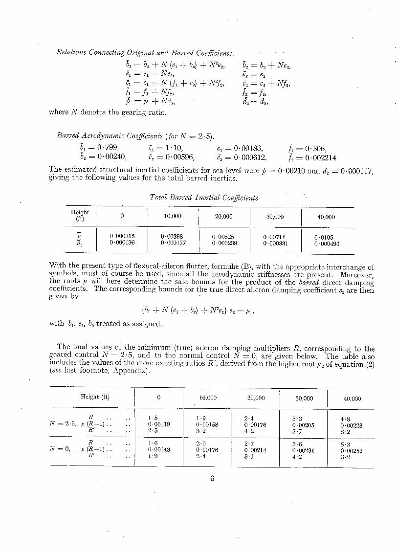
Relations Connecting Original and Barred Coefficients.
bl = bl + N (el -5. b2) + N~e~, 81 = el + Ne2, 51 = cl --t- N (fl -]- c~) + N2f2, /I=fl +NA,
The estimated structural inertial coefficients for sea-level were p = 0. 00210 and d2 = 0.000117, giving the following values for the total barred inertias.
Total Barred Inertial Coefficients
Height (ft)
dz 0"000315 0"000136
10,000
0"00398 0.000177
20,000
0.00525 0"000239
30,000
0.00714 0.000331
40,000
0.0105 0-000494
With the present type of flexural-aileron flutter, formula (B), with the appropriate interchange of symbols, must of course be used, since all the aerodynamic stiffnesses are present. Moreover, the roots ~ will here determine the safe bounds for the product of the barred direct damping coefficients. The corresponding bounds for the true direct aileron damping coefficient e2 are then given by
{b~ + N (el + b2) + N~'e2} e2 = # ,
with bl, el, b.~ treated as assigned.
The final values of the minimum (tree) aileron damping multipliers R, corresponding to the geared control N = 2.5, and to the normal control N = 0, are given below. The table also includes the values of the more exacting ratios R', derived from the higher root/~2 of equation (2) (see last footnote, Appendix).
Height (ft)
N = 2.5, R
p (R--l) . ~ ! . .
N = 0 , R
p (R- l ) R ! . ,
. °
• °
1.5 0.00119 2.5
1.6 0.00143 1 . 9
10,000
1.9 0. 00158 3 ' 2
2.0 0'00176 2.4
20,000
2-4 0"00176 4-2
2.7 0" 00214 3"1
30,000
3"3 0 -00205 5"7
3.6 0.00231 4.2
40,000
4.8 0' 00223 8.2
5"3 0-00252 6.2
6
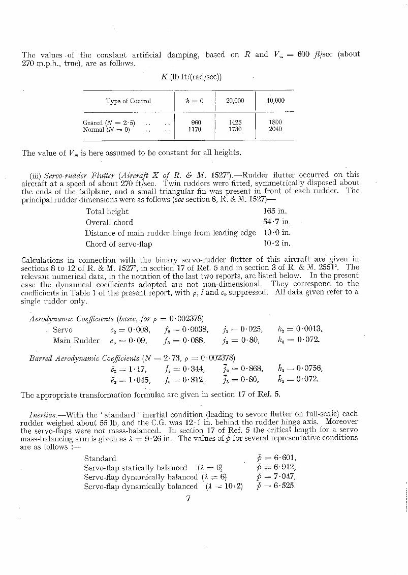
The values .of the constant artificial damping, based 270 m.p.h., true), are as fotlows.
K (lb ft/(md/sec))
on R and V,, , --600 fl/sec (about
Type of Control
Geared ( N = 2.5) . . . . Normal (N = 0) . . . .
~ = 0
960 1170
20,000
1425 1730
40,000
1800 2040
The value of V,,, is here assmned to be constant for all heights.
(iii) Servo-rudder Flutter (Aircraft X of R. & M. 152T) . - -Rudder flutter occurred on this aircraft at a speed of about 270 ft/sec. Twill rudders were fitted, symmetr ical ly disposed about the ends of the tailplane, and a small t r iangular fin was present in front of each rudder. The principal rudder dimensions were as follows (see section 8, R. & M. 1 5 2 7 ) -
Total height 165 in.
Overall chord 54.7 in.
Distance of main rudder hinge from leading edge 10-0 in.
Chord of servo-flap 10.2 in.
Calculations in connection with the binary servo-rudder flutter of this aircraft are given in sections 8 to 12of R. & M. 15277, in section 17 of Ref. 5 and in section 3 of R. & M. 255P. The relevant numerical data, in the nota t ion of the last two reports, are listed below. In the present case the dynamical coefficients adopted are not non-dimensional. They correspond to the coefficients in Table 1 of the present report, with p, I and Co suppressed. All data given refer to a single rudder only.
Aerodvnamw Coefficients (basic, for p = 0" 002378)
The appropriate t ransformat ion formulae are given in section 17 of Ref. 5.
Jnertias.--With the ' s tandard ' inertial condit ion (leading to severe flutter on full-scale) each rudder weighed about 55 lb, and the C.G. was 12.1 in. behind the rudder hinge axis. Moreover the servo-flaps were not mass-balanced. In section 17 of Ref. 5 the critical length for a servo mass-balancing arm is given as ~ = 9.26 in. The values of/$ for several representat ive conditions a~e as follows : - -
The minillmm multipliers for the true main-rudder damping are summarized below.
Servo-rudder Flutter (Aircraft X)
Ine r t i a l Condi t ion R (from root ~1)
R (from roo t /~ )
S t a n d a r d . . Servo-flap staticaily baianced'(i = d)" [[ :[
. . . . d y n a m i c a l l y ,, (~ = 6) . . . .
. . . . . . . . (;t = 10-2) . . . .
1 "33 1 "34 1 "35 1 "33
2-43 2"49 2"52 2"42
If the damping is assumed applied to the fla, p, instead of to the main rudder, the required minimum multiplier is of the order 13.5.
The values of artificial damping for each main rudder, derived from root ~,a and estimated for sea-level and V,,, = 300 ft/sec, are K = 79 for the standard servo and. K = 84 for the dynamically balanced servo (t == 6).
A P P E N D I X
Proofs of the Formulae
4. Class A Binary Flutter.--In Tab]e 1 (a) the relevant dynamical coefficients are appropriate to flexural-aileron flutter and are expressed in the non-dimensional form. The reference section lies at a distance 1 from the wing root, and Co denotes the root chord. In this case the two dynamical coordinates are the linear noimal displacement of the wing at the reference section divided by l, and the aileron angle. "I he inertial coefficients are expressible as follows : -
Let m denote the mass at distance y from the root and at distance CoO behind the aileron hinge ax i s . Also let .fy denote the ratio of the linear normal displacemen~ of the wing at distance y from the root to the corresponding displacement at the reference section. Then the total inertial coefficients are given by
s'/ °) a l ~ 7¢t plCo" -{- a l o ,
m ,hfdplCo + ]50,
m o~/flcO) + d2o,
where alo, P0, d20 denote the aerodynamic inertias, and ~ . , ~ . denote respectively summation
over the complete wing (with aileron) and over the aileron only.
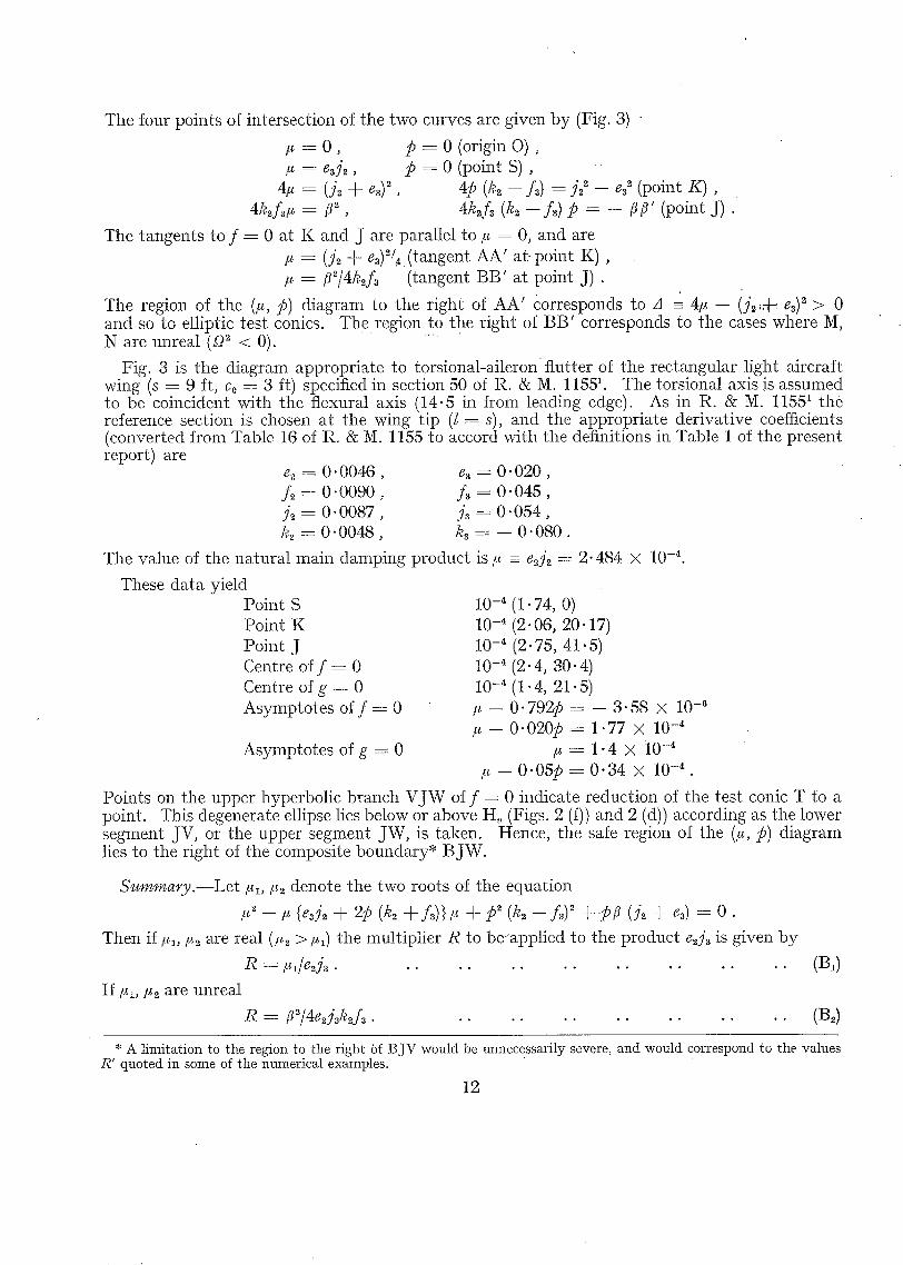
Fig. 1 (a) shows the noimal type of test-conic diagram for flexural-aileron flutter, when the aileron is mass-underbalanced. The stiffness point Z(0, f2) has the positive ordinate f~, and the points of intersection M, N, M', N ' of the conic with the coordinate axes are all real. In particular, the positions of M and N m-e given by OM = $/bl and ON = ~/e2. Hence
o z - -t Vl/b,.
8
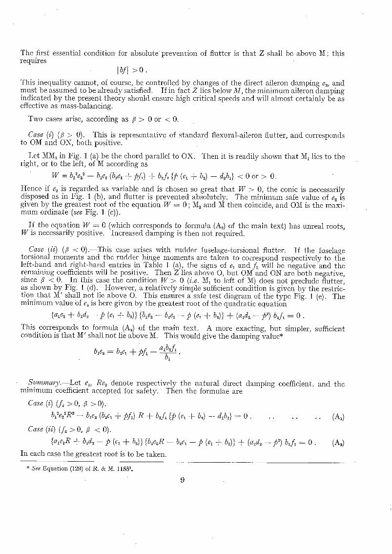
The first essential condition, for absolute prevention of flutter is that Z shall be above M: this requires
]bf] > 0 .
This inequality cannot, of course, be controlled by changes of the direct aileron damping e2, and must be assumed to be already satisfied. If in fact Z lies below M, the minimum aileron damping indicated by the present theory should ensure high critical speeds and will almost certainly be as effective as mass-balancing.
Two cases arise, according as /~ > 0 or < 0.
Case (i) (/~ > 0).--This is representative of standard flexural-aileron flutter, and corresponds to OM and ON, both positive.
Let MM1 in Fig. 1 (a) be the chord parallel to OX. Then it is readily shown that M~ lies to the right, or to the left, of M according as
Hence if e~ is regarded as variable and is chosen so great that W > 0, the conic is necessarily d!sposed as in Fig. 1 (b), and flutter is prevented absolutely. The minimum safe value of e2 is gtven by the greatest root of the equation W ---- 0 ; M2 and M then coincide, and OM is the maxi- mum ordinate (see Fig. I (c)).
If the equation W = 0 (which corresponds to forma!a (As) of the main text) has unreal roots, W is necessarily positive. Increased damping is then not required.
Case (ii) (fl < 0).--This case arises with rudder fuselage-torsional flutter. If the faselage torsional moments and the rudder hinge moments are taken to correspond respectively to the left-hand and right-hand entries in Table 1 (a), the signs of ex and f~ will be nega t iveand the remaining coefficients will be positive. Then Z lies above O, but OM and ON are both negative, since /~ < 0. In this case the condition W > 0 (i.e. 1~ to left of N) does not preclude flutter, as shown by Fig. 1 (d). However, a relatively simple sufficient condition is given by the restric- tion that M' shall not lie above O. This ensures a safe test diagram of the type Fig. 1 (e). The minimum value of e~ is here given by the greatest root of the quadratic equation
This corresponds to formula (A~) of the main text. A more exacting, but simpler, sufficient condition is that M' shall not lie above M. This would give the damping value*
b~e~ - . b...e~ + pf~ - - a~b~f~. b1
. S ! , m ~ m a r y . l L e t e.~, Re2 denote respectively the natural direct damping coefficient, and the minimum coefficient accepted for safety. Then the formulae are
C~se (i) (A > 0, ~ > 0).
b ? ~ R ~ - - ble~ ( b ~ + ~fl) R + b~f~ {p (el + b~) - - d~t~} --- 0 . . . . . . . (&)
Case (ii) (f~ > O, fl < 0).
{ a ~ R + b,d~ - p (~ + b~)) {blear -- b ~ -- p (e~ + t,~)) + (a~d~ -- ~ ) b2f~ = O. (A~)
In each case the greatest root is to be taken.
* S e e :Equation (129) of R. & M. 11551.
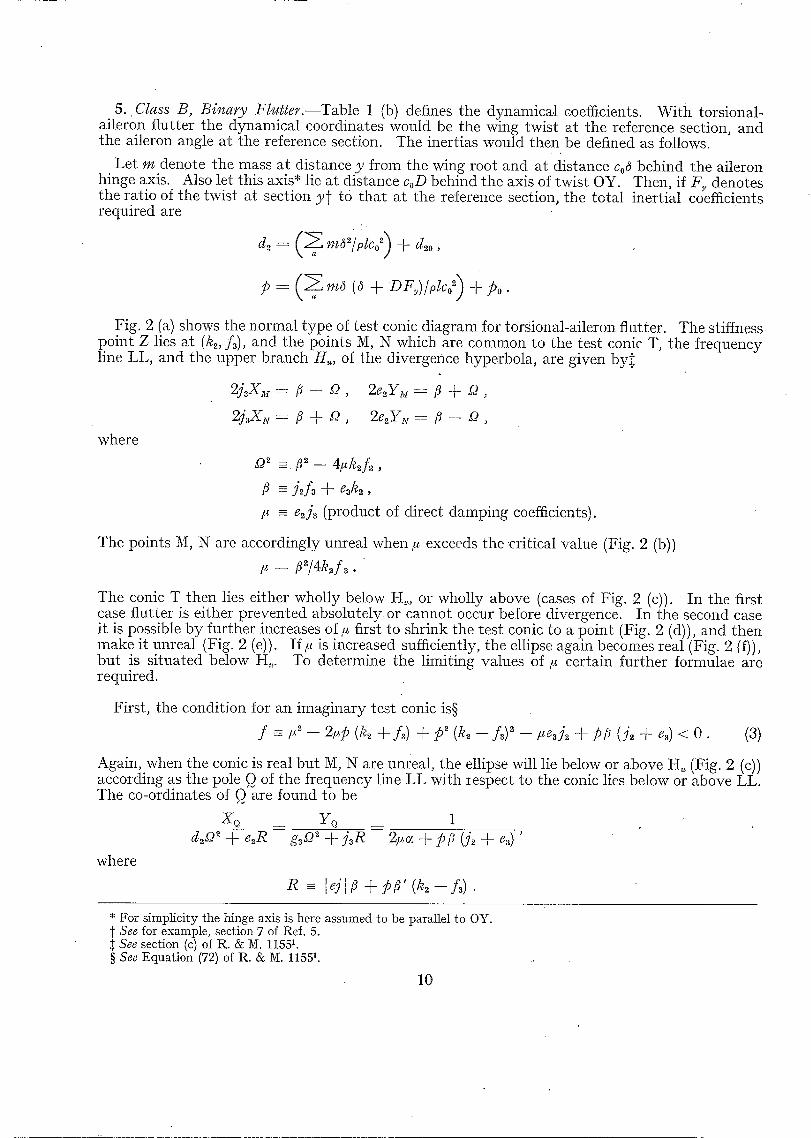
5 . Class B, Binary Flutter.lTable 1 (b) defines the dynamical coefficients. With torsional- aileron flutter the dynamical coordinates would be the wing twist at the reference section, and the aileron angle at the reference section. The inertias would then be defined as follows.
Let m denote the mass at distance y from the wing root and at distance Cod behind the aileron hinge axis. Also let this axis* lie at distance coD behind the axis of twist OY. Then, if Fy denotes the ratio of the twist at section y~ to that at the reference section, the total inertial coefficients required are
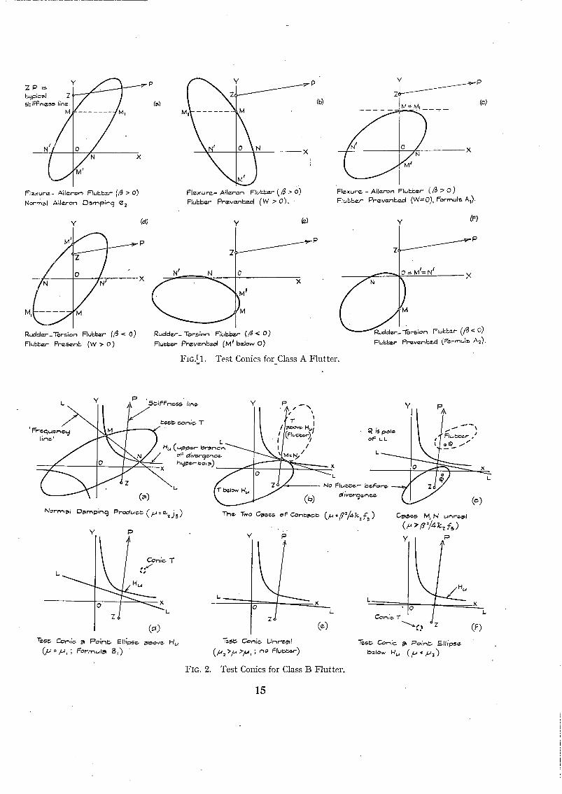
Fig. 2 (a) shows the normal type of test conic diagram for torsional-aileron flutter. The stiffness point Z lies at (k,, f3), and the points M, N which are common to the test conic T, the frequency line LL, and the upper branch H,, of the divergence hyperbola, are given by,t
where
2j3X~--: ~ - - ~ , 2e~YM-- fl + ~.),
/~ - e~ A (product of direct damping coefficients).
The points M, N are accordingly unreal when # exceeds the critical value (Fig. 2 (b))
/z = ~/4k2f 3.
The conic T then lies either wholly below H,,, or wholly above (cases of Fig. 2 (c)). In the first case flutter is either prevented absolutely or cannot occur before divergence. In the second case it is possible by further increases o f , first to shrink the test conic to a point (Fig. 2 (d)), and then make it unreal (Fig. 2 (e)). If t* is increased sufficiently, the ellipse again becomes real (Fig. 2 (f)), but is situated below H,. To determine the limiting values of/~ certain further formulae are required.
First, the condition for an imaginary test conic is§
f -=-Y'--2,,p(k~+f3) +p2(k~- -A)~- -~e3A + p ~ ( A +e~)<O. (3)
Again, when the conic is real but M, N are unreal, the ellipse will lie below or above H, (Fig. 2 (c)) according as the pole Q of the frequency line LL with ~espect to the conic lies below or above LL. The co-ordinates of Q are found to be
* For simplicity the hinge axis is here assumed to be parallel to OY. t See for example, section 7 of Ref. 5.
See section (c) of R. & M. 11551. § See Equation (72) of R. & M. 11551.
10
These relations yield, after some reduc t ion
j~XQ + e2YQ - - {3 - - ~2q , 2~c,. + p ~ (A + e~)
Hence, if a t tent ion is restr icted to the case s9 ~ < 0 (M, N unreal) the point Q lies below or above H,, accord ing as
2l~+pfl(j2+e3) > Oor < 0 .
On subst i tut ion for c~ from Table 1 this inequal i ty can be wri t ten
g =_ 2~ ~ - - 2~p (k~ + f ,) - - 2,ue~j2 + p/~ (j2 + e3) > 0 or < 0 . . . . . (4)
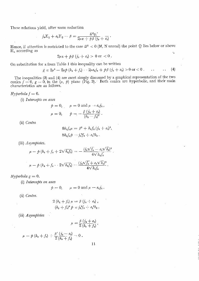
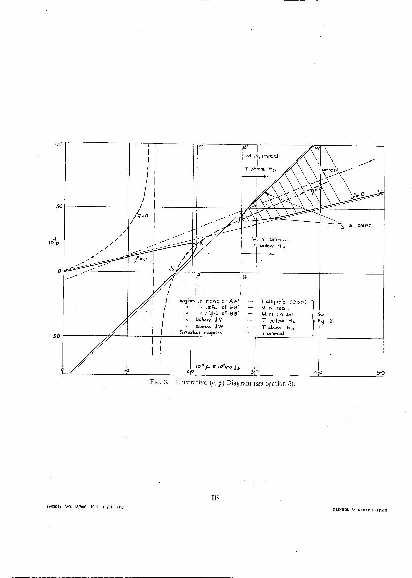
The inequalit ies (3) and (4) are most s imply discussed by a .graphical representat ion of the two conics f = 0, g = 0, in the (~, p) plane (Fig. 3 ) . Both comcs are hyperbolic, and their main characteristics are as follows.
Hyperbola f = O.
(i) Intercepts on axes
p - o ,
# = 0 ,
(ii) Centre
= 0 a n d # = e~j~,
15--,
= e 2 sk.,Lf, ~ + k2A (A + ~), " 2 Sk~f,p = 327~ + e~k~ •
(iii) Asymptotes .
- p (k2 + f,~ + 2vk~f0) = - ( A V T - e ~ / ~ ! ~ 4~/k.~f~
4~k2A
Hyperbola g = O.
(i) Intercepts on axes
p = o , # = 0 a n d , . = e3j~.
(ii) Centre.
2 (k~ + L),,, = ~ (L + e~),
(k~ + A)~p =- j£f~ + e?k2.
(iii) Asymptotes
" - 2 (k2 + A)'
- p ( k ~ + L ) + ~' ( j ~ - e . . ) - o . 2(k~ + L )
11
The four points of intersection of the two curves are given by (Fig. 3) "
K and J are parallel to ~, = 0, and are = (j~ + e~)~/~ ( tangent AA' at-point K ) , = f l~ /4kJ3 ( tangent BB ' at point J ) .
The region of the (~,, p) diagram to the r ight of AA' Corresponds to A = 4~ -- ( j2 ,~ e3) ~ > 0 and so to elliptic test conics. T h e region t O the r ight of B B ' corresponds to the cases where M, N are unreal (P- 2 < 0).
Fig. 3 is the diagram appropria te to tors ional-ai leron flutter of the rectangular l ight aircraft wing (s = 9 It, Co -- 3 It) specified in section 50 of R. & M. 1155L The torsional axis is assumed to be coincident wi th the flexural axis (14.5 in from leading edge). As in R. & M. 11551 the reference section is chosen at the wing t ip (l = s), and the appropriate derivat ive coefficients (converted from Table 16 of R. & M. 1155 to accord wi th the definitions in Table 1 of the present report) are
Points on the upper hyperbolic branch V J W of f = 0 indicate reduct ion of the test conic T fo a point. This degenerate ellipse lies below or above H,, (Figs. 2 (f)) and 2 (d)) according as the lower segment JV, or the upper segment JW, is taken. Hence, the safe region of the (~, p) diagram lies to the r ight of the composite boundary* BJW.
S u m m a r y . - - L e t / ~ 1 , ~2 denote the two roots of the equat ion
# ~ - - ~ t { e ~ j ~ + 2p (k~ +f~)}/,~ q - p ~ ( k 2 - - f ~ ) ~ + , p f l ( j 2 - k - e 3 ) = 0 .
Then if ~q, #~ are real (#~ > #1) the mult ipl ier R to be~applied to the product e~j~ is given by
* A limitation to the region to the right Of BJV would be unnecessarily severe, and would correspond to tile values R' quoted in some of the numerical examples.
12
No. Author 1 R.A. Frazer and W. J. Duncan.. 2 V.M. Falkner . . . . . .
3 R.A. Frazer . . . . . .
4 R.A. Frazer and W. J. Duncan..
5 R.A. Frazer and W. P. Jones ..
6 W.P. Jones . . . . -.
7 W.J . Duncan and A. R. Collar ..
• °
• •
R E F E R E N C E S
Title, etc. The Flutter of Aeroplane Wings. R. & M. 1155. August, 1928. Effect of Variation of Aileron Inertia and Damping on Flexural-
aileron Flutter of a Typical Cantilever Wing. R. & M. 1685. October, 1935.
Graphic£1 Treatment of Binary Mass-balancing Problems• R. & ~.~ 2551. August, 1942.
The Flutter of Monoplanes, Biplanes and Tail Units. R. & M. 1225. May, 1927.
Wing-aileron-tab Flutter. A.R.C. 5668. March, 1942. (To be published), i
Effect of a Flexurally-geared Aileron Control on the Binary Flutter of a Wing-aileron System. R. & M. 2362. February, 1924.
Binary Servo-rndder Flutter• R. & M. 1527. February, 1933.
T A B L E 1
D y n a m i c a l Coefficients and s u p p l e m e n t a r y Symbols
(a) Class A F l u t t e r ( T y p i f i e d b y F lexura l -Ai l e ron Flu t te r ) •
Flexural Moments Aileron hinge-Moments
Non-dimensional Non-dimensional Coefficient Significance Form Coefficient Significance Form
pZco~p pVlco~ea p V2lco2f 3 plco~3 p Vlco~j8 pV~lco~Y
X = (a~/pV~lCo ~) + A ,
q,' ; d2A + g~e, - P (L + e~), 13
y =_ (mo/PV~lco ~) + k . , o: =- l d l - - ~ (k. + A ) ,
=_ + x / ~ ~ - 4 e ~ A k J ~ ,
TABLE 2
Surnmary of Results of Numerical Examples (sections 2 and 3)
Aircraft Type
Modern fighter 3, 5 (example 2 (i))
Biplane (example 2 (iii)) . .
Large civil t ranspor t 6 (example 3(ii))
Military t ransporff (twin-tail) • (example 3 (iii)).
v~ (ft/sec)
800
300
600
Specification of F lu t te r T y p e Control Surface
Flexural-ai leron Fabr ic covered ailerons . . A l u m i N u m covered . .
Multiplier R (main control surface)
h = O
2 .7 8 .5
3 .0
20,000
2.4
2 .7
40,000
9 .4 33
4-8
5 .3
Artificial Damping K (lb ft /rad/sec)
63 2s3
': 20-4
300
Rudder- tors ional Rudder horn-balanced and above fuselage axis
Flexural - aileron Control circuit offset f rom (geared) neut ra l axis
Flexural - aileron Control circuit normal . .
Servo-rudder . . Servo not mass-balanced Servo dynamical ly balanced
1-5
1"6
1 "33 1 "35
96O
1170
79 84
20,000 40,000
7 7 298
1425- 1800
1730 2040
Notes. (a) R is defined as tile ratio of tile m i n i m u m d i r e c t d a m p i n g coefficient %1 absolute flutter prevention to the na tu ra l direct damping coefficient.
• (b) K denotes the constant artificial damping to be applied to each relevant main control surface, and measures the addi t ional damping hinge moment (lb ft) whei1 tha t surface is tu rned uniformly at tile ra te of 1 rad/sec.
~ 1 ° 12 - ~ I / " l~; -~ I r ~ . ~ ~, . I / , / I - 7
Th~ "r,,,o c _ ¢ ~ , , F c o , . = , ~ (p:p , / ,~ f~) ~ , ~ M , N ,.,,-,,'-~l
v ~
T¢~_. Cemi~ I.Jmr'~4~l
y P
L
FIG. 2. Test Conics for Class B Flutter.
15
I00
50
-SO
I /
/
J I
!
I
M, N, u n r ~ l
I /
/ / /
l /,
I I I ~ i o n eo r ;ghk oF A A'
I . . . . Je~/; o F B B '
I ,, ~ r;ghk oF BB' ,, below J V
I ,, ~ v ~ J w S h ~ : l c d r~ion
M, tN u n r ~ l . 7 below H u
i
T~lh'p~ic Ca>o) I M , ~ rtz~,l. M, i"t unr~z~l T I:xzlow H u T ~bovc H u T umr-~l
7" 3 a Foint:.
5¢e Fiq . 2.
. o z io 3~o 4 o s-o r
FIG. 3. I l l u s t r a t i v e (/z, p ) D i a g r a m (see S e c t i o n 5).
16 (93004) Wt. 13/806 K . 5 l l /51 Hw. PR]NT~D IN GREA~ BRIrA[~
R. & M. No. 2 ~ 2 (7478)
A.R.C. Teelmie, ai R e ~
Publications of Aeronautical Research
the Council
ANNUAL TECHNICAL REPORTS OF T H E AERONAUTICAL RESEARCH COUNCIL (BOUND VOLUMES) - -
z934-35 Vol. I. Aerodynamics. Out ofprint. Vol. II. Seaplanes, Structures, Engines, Materials, etc. 4os..(4os. 8d.)
I935-36 Vol. I. Aerodynamics. 3os. (3os. 7d.) Vol. II. Structures, Flutter, Engines, Seaplanes, etc. Sos. (3os. 7d.)
I936 Vol. I. Aerodynamics General, Performance, Airscrews, Flutter and Spinning. 4os. (4os. 9d.)
Vol. II. Stability and Control, Structures, Seaplanes, Engines, etc. 5os. (5os. xod.)
I937 Vol. L Aerodynamics General, Performance, Airscrews, Flutter and Spinning. 4os. (4os. zod.)
Vol. II. Stability and Control, Structures, Seaplanes, Engines, etc. 6os. (6Is.)
I938 Vol. I. Aerodynamics General, Performance, Airscrews. 5os. (Sis.) Vol. II. Stability and Control, Flutter, Structures, Seaplanes, Wind Tunnels,
Materials. 3os. (3os. 9d.)
I939 Vol. I. Aerodynamics General, Performance, Airscrews, Engines. 5os. ($os. I xd.) Vol. II. Stability and Control, Flutter and Vibrat.~on, Instruments, Structures,
Seaplanes, etc. 63s. (64s. 2d.)
I94o Aero and Hydrodynamics, Aerofoils, Airscrews, Engines, Flutter, Icing, 8tabifity and Control, Structures, and a miscellaneous section. 5os. (5Is.}
Certain other reports proper to the I94o volume will subsefuentty he included in a separate volume.
ANNUAL REPORTS OF T H E AERONAUTICAL RESEARCH COUNCIL-~
I933-34 1934-35
April I, I935 to I937 I938
I939-48
INDEX T O ALL REPORTS AND TECHNICAL REPORTS, AND
April, 195o
Is. 6d. (Is. 8d.) Is. 6d. (Is. 8d.)
December 3i, i936. 4 s. (4 s. 4d.) 2s. (2s. o d.) Is. 6d. (Is. 8d.) 3s. (3s. 2d.)
MEMORANDA PUBLISHED IN THE ANNUAL SEPARATELY--
R. & M. No. 2600. 2s. 6d. (2s. 7½d.)
INDEXES T O T H E TECHNICAL COUNCIL---
December r, I 936 - - June 30, I939. July I, I 9 3 9 - - June 3 o, i945. july I, I945 - - J u n e 3 o, i946. July I, I 9 4 6 - - December 3 z, i946. January i, z947 - - June 3 o, I947.
REPORTS OF T H E AERONAUTICAL RESEARCH
" R. & M. No. I85o. R. & M. No. I95o. R. & M. No. 2050. R. & M. No. 215o. R. & M. No. 2250.
Is.4d. Os. 4{4.) Is. Os. i½d.) Ig. (IS. I~d,) is. 3d. 0s. 44t.) is. 3d. (Is. 4~d.)
$.O. Code No. ~$'~552
Prices in brackets include postage.
Obtainable from
HIS MAJESTY'S STATIONERY OFFICE York House, Kingsway, LONDON, W.C.2 429 Oxford Street, LONDON, Wol