26
pentair.com FLECK® 5000 CONTROL VALVE SERVICE MANUAL
pentair.com
FLECK® 5000 CONTROL VALVE SERVICE MANUAL
JOB SPECIFICATION SHEETJob Number: ___________________________________________________
Model Number: _________________________________________________
Water Hardness: ______________________________________ ppm or gpg
Capacity Per Unit: _______________________________________________
Mineral Tank Size: ______________ Diameter: ________ Height: _________
Salt Setting per Regeneration: _____________________________________
Regenerant Flow: Upflow Downflow
1. Meter Size:
A. 3/4" Paddle Wheel
B. 3/4" Turbine
C. 1" Paddle Wheel (Not Used)
D. 1" Turbine (Not Used)
E. 1-1/2" Electronic Inline Plastic Turbine (Not Used)
F. 1-1/2" Paddle Wheel (Not Used)
G. 2" Paddle Wheel (Not Used)
H. Generic_________Pulse Count__________Meter Size__________ ________________
2. System Type:
A. System #4: 1 Tank, 1 Meter, Immediate, or Delayed Regeneration
B. ___________________________________________________ System #4: Time Clock
3. Control Program Settings:
A. Backwash: ________________________________________________________Minutes
B. Brine and Slow Rinse: ______________________________________________Minutes
C. Rapid Rinse: ______________________________________________________Minutes
D. BrineTankRefill: __________________________________________________Minutes
E. Pause Time: ______________________________________________________Minutes
F. Second Backwash: ________________________________________________Minutes
4. Drain Line Flow Control: __________________________________ gpm
5. Brine Line Flow Control: __________________________________ gpm
6. Injector Size#: _________________________________________
TABLE OF CONTENTS
Job Specification Sheet ...................................................... 2
Typical Residential System Plumbing ...................................3
Start-Up Instructions/Flushing & Conditioning ................... 4
System Disinfection ............................................................ 4
Installation Instructions .......................................................5
Start-Up Instructions ...........................................................6
Timer Features .....................................................................6
Master Programming Mode/Chart ........................................8
User Programming Mode .................................................... 12
Diagnostic Programming Mode .......................................... 13
Control Valve Assembly ...................................................... 14
Valve Accessories .............................................................. 16
Valve Assemblies ............................................................... 17
Turbine Meter Assembly - P/N 60626 ................................. 18
Paddle Meter Assembly - P/N 60086-50 ............................. 18
Bypass Valve Assembly (Metal) ........................................... 19
Bypass Valve Assembly (Plastic) ......................................... 19
Safety Brine Valve ............................................................. 20
Dimensional Drawings ........................................................ 21
Water Conditioner Flow Diagrams ......................................22
Injector Flow Data ............................................................. 24
Wiring Diagram ..................................................................25
IMPORTANT PLEASE READ: • The information, specifications and illustrations in
this manual are based on the latest information available at the time of printing. The manufacturer reserves the right to make changes at any time without notice.
• This manual is intended as a guide for service of the valve only. System installation requires information from a number of suppliers not known at the time of manufacture. This product should be installed by a plumbing professional.
• The system is not intended to be used for treating water that is microbiologically unsafe or of unknown quality without adequate disinfection before or after the system. This product must be installed in compliance with all state and municipal plumbing and electrical codes. Permits may be required at the time of installation.
• It is established that when daytime water pressure exceeds 80 psi (5.5 bar), the maximum pressure rating of 125 psi (8.6 bar) can be exceeded. A pressure regulator must be installed on this system or warranty is voided.
• Do not install the unit where temperatures may drop below 32°F (0°C) or above 125°F (52°C).
• Do not place the unit in direct sunlight. Black units will absorb radiant heat increasing internal temperatures. Do not strike the valve or any of the components.
• Warranty of this product extends to manufacturing defects. Misapplication of this product may result in failure to properly condition water, or damage to product. A prefilter should be used on installations in which free solids are present.
• In some applications local municipalities treat water with Chloramines. High Chloramine levels may damage valve components.
• Correct and constant voltage must be supplied to the controller to maintain proper function.
2 • PENTAIR® FLECK® 5000 Control Valve Service Manual
This valve is Tested and Certified by the WQA against NSF Std. 44 for performance, structural integrity and Performance & NSF Std. 372 for low lead compliance and CSA B483.1 for Canada.
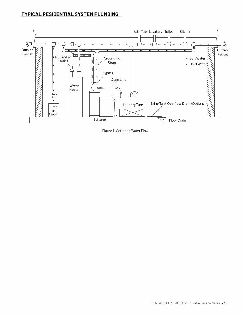
TYPICAL RESIDENTIAL SYSTEM PLUMBING
Soft Water
Hard Water
OutsideFaucet
OutsideFaucet
Bath Tub Lavatory Toilet Kitchen
Laundry TubsPump or
Meter
Hot Water Outlet
Water Heater
Brine Tank Over�ow Drain (Optional)
Floor Drain
Drain Line
Bypass
Softener
GroundingStrap
Figure 1 Softened Water Flow
PENTAIR FLECK 5000 Control Valve Service Manual • 3

SYSTEM DISINFECTION
Disinfection of Water SoftenersThe materials of construction of the modern water softener will not support bacterial growth, nor will these materials contaminate a water supply. During normal use, a softener may become fouled with organic matter, or in some cases with bacteria from the water supply. This may result in an off-taste or odor in the water.
Some softeners may need to be disinfected after installation and some softeners will require periodic disinfection during their normal life.
Depending upon the conditions of use, the style of softener, the type of ion exchanger, and the disinfectant available, a choice can be made among the following methods.
Sodium or Calcium Hypochlorite
ApplicationThese materials are satisfactory for use with polystyrene resins, synthetic gel zeolite, greensand and bentonites.
5.25% Sodium HypochloriteThese solutions are available under brands names of household bleach. If stronger solutions are used, such as those sold for commercial laundries, adjust the dosage accordingly.
Dosage
A. Polystyrene resin; 1.2 fluid ounce (35.5 ml) per cubic foot.
B. Non-resinous exchangers; 0.8 fluid ounce (23.7 ml) per cubic foot.
1. Salt tank softeners
A. Backwash the softener and add the required amount of hypochlorite solution to the well of the salt tank. The salt tank should have water in it to permit the solution to be carried into the softener.
B. Proceed with the normal recharge.
Calcium HypochloriteCalcium hypochlorite, 70% available chlorine, is available in several forms including tablets and granules. These solid materials may be used directly without dissolving before use.
1. Dosage
A. Two grains (approximately 0.1 ounce [3 ml]) per cubic foot.
2. Salt tank softeners
A. Backwash the softener and add the required amount of hypochlorite to the well of the salt tank. The salt tank should have water in it to permit the chlorine solution to be carried into the softener.
B. Proceed with the normal recharge.
START-UP INSTRUCTIONS/ FLUSHING & CONDITIONINGThe water softener should be installed with the inlet, outlet, and drain connections made in accordance with the manufacturer’s recommendations, and to meet applicable plumbing codes.
1. Program the valve control according to instructions shown in this manual.
2. Start an immediate regeneration by holding the Extra Cycle button for five seconds. Position the valve to backwash. Ensure the drain line flow remains steady for 10 minutes or until the water runs clear.
3. Position the valve to the brine draw/slow rinse position. Ensure the unit is drawing water from the brine tank (this step may need to be repeated).
4. Position the valve to the rapid rinse position. Check the drain line flow, and run for five minutes or until the water runs clear.
5. Position the valve to the start of the brine tank fill cycle. Ensure water goes into the brine tank at the desired rate. The brine valve drive cam will hold the valve in this position to fill the brine tank for the first regeneration.
6. Replace control cover.
7. Put salt in the brine tank. NOTE: Do not use granulated or rock salt.
4 • PENTAIR FLECK 5000 Control Valve Service Manual
PENTAIR FLECK 5000 Control Valve Service Manual • 5
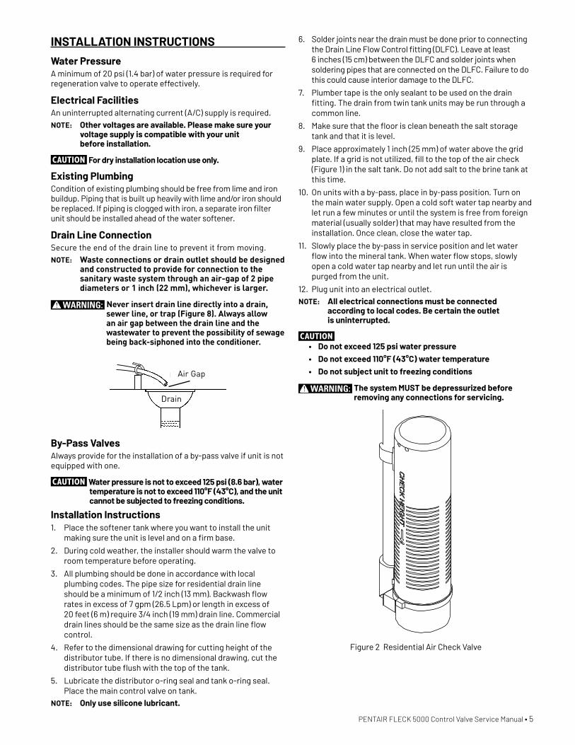
INSTALLATION INSTRUCTIONS
Water PressureA minimum of 20 psi (1.4 bar) of water pressure is required for regeneration valve to operate effectively.
Electrical FacilitiesAn uninterrupted alternating current (A/C) supply is required.NOTE: Other voltages are available. Please make sure your
voltage supply is compatible with your unit before installation.
CAUTION For dry installation location use only.
Existing PlumbingCondition of existing plumbing should be free from lime and iron buildup. Piping that is built up heavily with lime and/or iron should be replaced. If piping is clogged with iron, a separate iron filter unit should be installed ahead of the water softener.
Drain Line ConnectionSecure the end of the drain line to prevent it from moving.NOTE: Waste connections or drain outlet should be designed
and constructed to provide for connection to the sanitary waste system through an air-gap of 2 pipe diameters or 1 inch (22 mm), whichever is larger.
WARNING: Never insert drain line directly into a drain, sewer line, or trap (Figure 8). Always allow an air gap between the drain line and the wastewater to prevent the possibility of sewage being back-siphoned into the conditioner.
Right WayAir Gap
Drain
By-Pass ValvesAlways provide for the installation of a by-pass valve if unit is not equipped with one.
CAUTION Water pressure is not to exceed 125 psi (8.6 bar), water temperature is not to exceed 110°F (43°C), and the unit cannot be subjected to freezing conditions.
Installation Instructions1. Place the softener tank where you want to install the unit
making sure the unit is level and on a firm base.
2. During cold weather, the installer should warm the valve to room temperature before operating.
3. All plumbing should be done in accordance with local plumbing codes. The pipe size for residential drain line should be a minimum of 1/2 inch (13 mm). Backwash flow rates in excess of 7 gpm (26.5 Lpm) or length in excess of 20 feet (6 m) require 3/4 inch (19 mm) drain line. Commercial drain lines should be the same size as the drain line flow control.
4. Refer to the dimensional drawing for cutting height of the distributor tube. If there is no dimensional drawing, cut the distributor tube flush with the top of the tank.
5. Lubricate the distributor o-ring seal and tank o-ring seal. Place the main control valve on tank.
NOTE: Only use silicone lubricant.
6. Solder joints near the drain must be done prior to connecting the Drain Line Flow Control fitting (DLFC). Leave at least 6 inches (15 cm) between the DLFC and solder joints when soldering pipes that are connected on the DLFC. Failure to do this could cause interior damage to the DLFC.
7. Plumber tape is the only sealant to be used on the drain fitting. The drain from twin tank units may be run through a common line.
8. Make sure that the floor is clean beneath the salt storage tank and that it is level.
9. Place approximately 1 inch (25 mm) of water above the grid plate. If a grid is not utilized, fill to the top of the air check (Figure 1) in the salt tank. Do not add salt to the brine tank at this time.
10. On units with a by-pass, place in by-pass position. Turn on the main water supply. Open a cold soft water tap nearby and let run a few minutes or until the system is free from foreign material (usually solder) that may have resulted from the installation. Once clean, close the water tap.
11. Slowly place the by-pass in service position and let water flow into the mineral tank. When water flow stops, slowly open a cold water tap nearby and let run until the air is purged from the unit.
12. Plug unit into an electrical outlet. NOTE: All electrical connections must be connected
according to local codes. Be certain the outlet is uninterrupted.
CAUTION • Do not exceed 125 psi water pressure• Do not exceed 110°F (43°C) water temperature• Do not subject unit to freezing conditions
WARNING: The system MUST be depressurized before removing any connections for servicing.
Figure 2 Residential Air Check Valve

6 • PENTAIR FLECK 5000 Control Valve Service Manual
STARTUP INSTRUCTIONSThe water softener should be installed with the inlet, outlet, and drain connections made in accordance with the manufacturer’s recommendations, and to meet applicable plumbing codes.
1. Turn the manual regeneraton knob slowly in a clockwise direction until the program micro switch lifts on top of the first set of pins. Allow the drive motor to move the piston to the first regeneration step and stop. Each time the program switch position changes, the valve will advance to the next regeneration step. Always allow the motor to stop before moving to the next set of pins or spaces.
NOTE: For electronic valves, please refer to the manual regeneration part of the timer operation section. If the valve came with a separate electronic timer service manual, refer to the timer operation section of the electronic timer service manual.
2. Position the valve to backwash. Ensure the drain line flow remains steady for 10 minutes or until the water runs clear (see above).
3. Position the valve to the brine / slow rinse position. Ensure the unit is drawing water from the brine tank (this step may need to be repeated).
4. Position the valve to the rapid rinse position. Check the drain line flow, and run for 5 minutes or until the water runs clear.
5. Position the valve to the start of the brine tank fill cycle. Ensure water goes into the brine tank at the desired rate. The brine valve drive cam will hold the valve in this position to fill the brine tank for the first regeneration.
6. Replace control box cover.
7. Put salt in the brine tank.NOTE: Do not use granulated or rock salt.
TIMER FEATURESParameter
DisplayData
DisplayPM
Indicator
Flow Indicator
x1000 Indicator
ServiceIcon
ProgrammingIcon
Extra CycleButton
UpButton
DownButton
Error/InformationIcon
Features of the SXT• Power backup that continues to keep time and the
passage of days for a minimum of 48 hours in the event of power failure. During a power outage, the control goes into a power-saving mode. It does not monitor water usage during a power failure, but it does store the volume remaining at the time of power failure.
• Settings for both valve (basic system) and control type (method used to trigger a regeneration).
• Day-of-the-Week controls.
• While in service, the display alternates between time of day, volume remaining or days to regeneration, and tank in service (twin tank systems only).
• The Flow Indicator flashes when outlet flow is detected.
• The Service Icon flashes if a regeneration cycle has been queued.
• A Regeneration can be triggered immediately by pressing the Extra Cycle button for five seconds.
• The Parameter Display displays the current Cycle Step (BW, BF, RR, etc) during regeneration, and the data display counts down the time remaining for that cycle step. While the valve is transferring to a new cycle step, the display will flash. The parameter display will identify the destination cycle step (BW, BF, RR, etc) and the data display will read “----”. Once the valve reaches the cycle step, the display will stop flashing and the data display will change to the time remaining. During regeneration, the user can force the control to advance to the next cycle step immediately by pressing the extra cycle button.
Setting the Time of Day1. Press and hold either the Up or Down buttons until the
programming icon replaces the service icon and the parameter display reads TD.
2. Adjust the displayed time with the Up and Down buttons.
3. When the desired time is set, press the Extra Cycle button to resume normal operation. The unit will also return to normal operation after 5 seconds if no buttons are pressed.
PENTAIR FLECK 5000 Control Valve Service Manual • 7
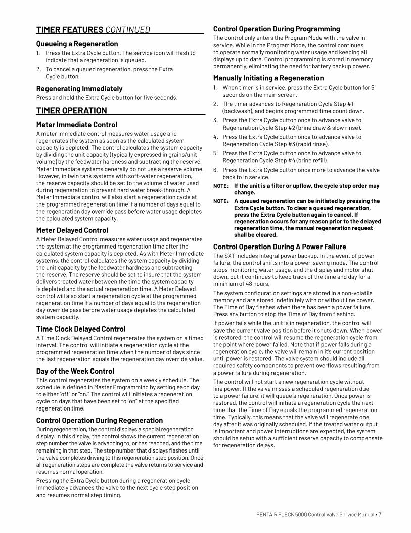
TIMER FEATURES CONTINUED
Queueing a Regeneration1. Press the Extra Cycle button. The service icon will flash to
indicate that a regeneration is queued.
2. To cancel a queued regeneration, press the Extra Cycle button.
Regenerating ImmediatelyPress and hold the Extra Cycle button for five seconds.
TIMER OPERATION
Meter Immediate ControlA meter immediate control measures water usage and regenerates the system as soon as the calculated system capacity is depleted. The control calculates the system capacity by dividing the unit capacity (typically expressed in grains/unit volume) by the feedwater hardness and subtracting the reserve. Meter Immediate systems generally do not use a reserve volume. However, in twin tank systems with soft-water regeneration, the reserve capacity should be set to the volume of water used during regeneration to prevent hard water break-through. A Meter Immediate control will also start a regeneration cycle at the programmed regeneration time if a number of days equal to the regeneration day override pass before water usage depletes the calculated system capacity.
Meter Delayed ControlA Meter Delayed Control measures water usage and regenerates the system at the programmed regeneration time after the calculated system capacity is depleted. As with Meter Immediate systems, the control calculates the system capacity by dividing the unit capacity by the feedwater hardness and subtracting the reserve. The reserve should be set to insure that the system delivers treated water between the time the system capacity is depleted and the actual regeneration time. A Meter Delayed control will also start a regeneration cycle at the programmed regeneration time if a number of days equal to the regeneration day override pass before water usage depletes the calculated system capacity.
Time Clock Delayed ControlA Time Clock Delayed Control regenerates the system on a timed interval. The control will initiate a regeneration cycle at the programmed regeneration time when the number of days since the last regeneration equals the regeneration day override value.
Day of the Week ControlThis control regenerates the system on a weekly schedule. The schedule is defined in Master Programming by setting each day to either “off” or “on.” The control will initiates a regeneration cycle on days that have been set to “on” at the specified regeneration time.
Control Operation During Regeneration During regeneration, the control displays a special regeneration display. In this display, the control shows the current regeneration step number the valve is advancing to, or has reached, and the time remaining in that step. The step number that displays flashes until the valve completes driving to this regeneration step position. Once all regeneration steps are complete the valve returns to service and resumes normal operation.
Pressing the Extra Cycle button during a regeneration cycle immediately advances the valve to the next cycle step position and resumes normal step timing.
Control Operation During Programming The control only enters the Program Mode with the valve in service. While in the Program Mode, the control continues to operate normally monitoring water usage and keeping all displays up to date. Control programming is stored in memory permanently, eliminating the need for battery backup power.
Manually Initiating a Regeneration1. When timer is in service, press the Extra Cycle button for 5
seconds on the main screen.
2. The timer advances to Regeneration Cycle Step #1 (backwash), and begins programmed time count down.
3. Press the Extra Cycle button once to advance valve to Regeneration Cycle Step #2 (brine draw & slow rinse).
4. Press the Extra Cycle button once to advance valve to Regeneration Cycle Step #3 (rapid rinse).
5. Press the Extra Cycle button once to advance valve to Regeneration Cycle Step #4 (brine refill).
6. Press the Extra Cycle button once more to advance the valve back to in service.
NOTE: If the unit is a filter or upflow, the cycle step order may change.
NOTE: A queued regeneration can be initiated by pressing the Extra Cycle button. To clear a queued regeneration, press the Extra Cycle button again to cancel. If regeneration occurs for any reason prior to the delayed regeneration time, the manual regeneration request shall be cleared.
Control Operation During A Power Failure The SXT includes integral power backup. In the event of power failure, the control shifts into a power-saving mode. The control stops monitoring water usage, and the display and motor shut down, but it continues to keep track of the time and day for a minimum of 48 hours.
The system configuration settings are stored in a non-volatile memory and are stored indefinitely with or without line power. The Time of Day flashes when there has been a power failure. Press any button to stop the Time of Day from flashing.
If power fails while the unit is in regeneration, the control will save the current valve position before it shuts down. When power is restored, the control will resume the regeneration cycle from the point where power failed. Note that if power fails during a regeneration cycle, the valve will remain in it’s current position until power is restored. The valve system should include all required safety components to prevent overflows resulting from a power failure during regeneration.
The control will not start a new regeneration cycle without line power. If the valve misses a scheduled regeneration due to a power failure, it will queue a regeneration. Once power is restored, the control will initiate a regeneration cycle the next time that the Time of Day equals the programmed regeneration time. Typically, this means that the valve will regenerate one day after it was originally scheduled. If the treated water output is important and power interruptions are expected, the system should be setup with a sufficient reserve capacity to compensate for regeneration delays.
8 • PENTAIR FLECK 5000 Control Valve Service Manual
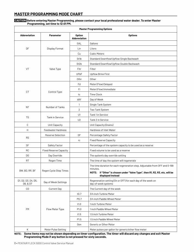
MASTER PROGRAMMING MODE CHARTCAUTION Before entering Master Programming, please contact your local professional water dealer. To enter Master
Programming, set time to 12:01 PM.
Master Programming Options
Abbreviation Parameter Option Abbreviation
Options
DF Display Format
GAL Gallons
Ltr Liters
Cu Cubic Meters
VT Valve Type
St1b Standard Downflow/Upflow Single Backwash
St2b Standard Downflow/Upflow Double Backwash
Fltr Filter
UFbF Upflow Brine First
Othr Other
CT Control Type
Fd Meter (Flow) Delayed
FI Meter (Flow) Immediate
tc Time Clock
dAY Day of Week
NT Number of Tanks1 Single Tank System
2 Two Tank System
TS Tank in ServiceU1 Tank 1 in Service
U2 Tank 2 in Service
C Unit Capacity Unit Capacity (Grains)
H Feedwater Hardness Hardness of Inlet Water
RSReserve Selection SF Percentage Safety Factor
rc Fixed Reserve Capacity
SF Safety Factor Percentage of the system capacity to be used as a reserve
RC Fixed Reserve Capacity Fixed volume to be used as a reserve
DO Day Override The system’s day override setting
RT Regen Time The time of day the system will regenerate
BW, BD, RR, BF Regen Cycle Step Times
The time duration for each regeneration step. Adjustable from OFF and 0-199 minutes.NOTE: If “Other” is chosen under “Valve Type”, then R1, R2, R3, etc, will be
displayed instead
D1, D2, D3, D4, D5, D6, & D7
Day of Week SettingsRegeneration setting (On or OFF) for each day of the week on day-of-week systems
CD Current Day The Current day of the week
FM Flow Meter Type
t0.7 3/4 inch Turbine Meter
P0.7 3/4 inch Paddle Wheel Meter
t1.0 1 inch Turbine Meter
P1.0 1 inch Paddle Wheel Meter
t1.5 1.5 inch Turbine Meter
P1.5 1.5 inch Paddle Wheel Meter
Gen Generic or Other Meter
K Meter Pulse Setting Meter pulses per gallon for generic/other flow meter
NOTE: Some items may not be shown depending on timer configuration. The timer will discard any changes and exit Master Programming Mode if any button is not pressed for sixty seconds.
PENTAIR FLECK 5000 Control Valve Service Manual • 9
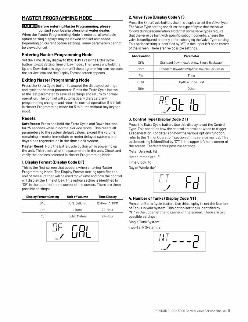
MASTER PROGRAMMING MODECAUTION Before entering Master Programming, please
contact your local professional water dealer.When the Master Programming Mode is entered, all available option setting displays may be viewed and set as needed. Depending on current option settings, some parameters cannot be viewed or set.
Entering Master Programming ModeSet the Time Of Day display to 12:01 P.M. Press the Extra Cycle button (to exit Setting Time of Day mode). Then press and hold the Up and Down buttons together until the programming icon replaces the service icon and the Display Format screen appears.
Exiting Master Programming ModePress the Extra Cycle button to accept the displayed settings and cycle to the next parameter. Press the Extra Cycle button at the last parameter to save all settings and return to normal operation. The control will automatically disregard any programming changes and return to normal operation if it is left in Master Programming mode for 5 minutes without any keypad input.
ResetsSoft Reset: Press and hold the Extra Cycle and Down buttons for 25 seconds while in normal Service mode. This resets all parameters to the system default values, except the volume remaining in meter immediate or meter delayed systems and days since regeneration in the time clock system.
Master Reset: Hold the Extra Cycle button while powering up the unit. This resets all of the parameters in the unit. Check and verify the choices selected in Master Programming Mode.
1. Display Format (Display Code DF)This is the first screen that appears when entering Master Programming Mode. The Display Format setting specifies the unit of measure that will be used for volume and how the control will display the Time of Day. This option setting is identified by “DF” in the upper left hand corner of the screen. There are three possible settings:
Display Format Setting Unit of Volume Time Display
GAL U.S. Gallons 12-Hour AM/PM
Ltr Liters 24-Hour
Cu Cubic Meters 24-Hour
2. Valve Type (Display Code VT)Press the Extra Cycle button. Use this display to set the Valve Type. The Valve Type setting specifies the type of cycle that the valve follows during regeneration. Note that some valve types require that the valve be built with specific subcomponents. Ensure the valve is configured properly before changing the Valve Type setting. This option setting is identified by “VT” in the upper left hand corner of the screen. There are five possible settings:
Abbreviation Parameter
St1b Standard Downflow/Upflow, Single Backwash
St2b Standard Downflow/Upflow, Double Backwash
Fltr Filter
UFbF Upflow Brine First
Othr Other
3. Control Type (Display Code CT)Press the Extra Cycle button. Use this display to set the Control Type. This specifies how the control determines when to trigger a regeneration. For details on how the various options function, refer to the “Timer Operation” section of this service manual. This option setting is identified by “CT” in the upper left hand corner of the screen. There are four possible settings:
Meter Delayed: Fd
Meter Immediate: FI
Time Clock: tc
Day of Week: dAY
4. Number of Tanks (Display Code NT)Press the Extra Cycle button. Use this display to set the Number of Tanks in your system. This option setting is identified by “NT” in the upper left hand corner of the screen. There are two possible settings:
Single Tank System: 1
Two-Tank System: 2
10 • PENTAIR FLECK 5000 Control Valve Service Manual
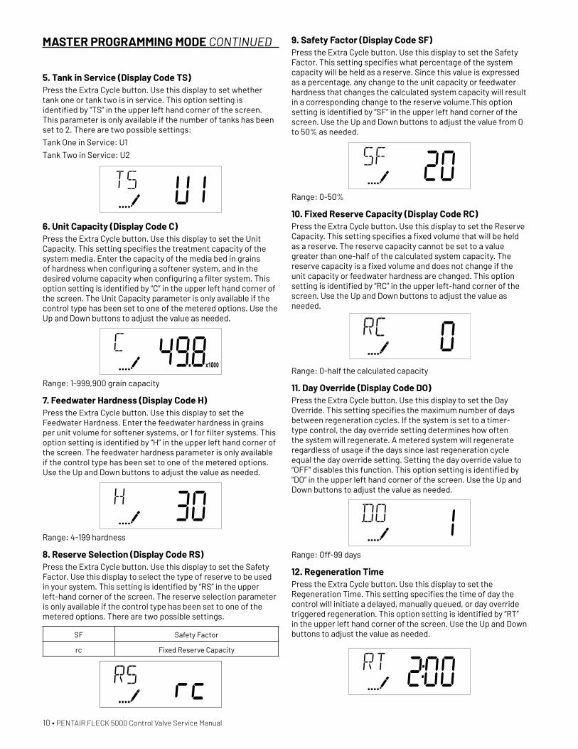
5. Tank in Service (Display Code TS)Press the Extra Cycle button. Use this display to set whether tank one or tank two is in service. This option setting is identified by “TS” in the upper left hand corner of the screen. This parameter is only available if the number of tanks has been set to 2. There are two possible settings:
Tank One in Service: U1
Tank Two in Service: U2
6. Unit Capacity (Display Code C)Press the Extra Cycle button. Use this display to set the Unit Capacity. This setting specifies the treatment capacity of the system media. Enter the capacity of the media bed in grains of hardness when configuring a softener system, and in the desired volume capacity when configuring a filter system. This option setting is identified by “C” in the upper left hand corner of the screen. The Unit Capacity parameter is only available if the control type has been set to one of the metered options. Use the Up and Down buttons to adjust the value as needed.
Range: 1-999,900 grain capacity
7. Feedwater Hardness (Display Code H)Press the Extra Cycle button. Use this display to set the Feedwater Hardness. Enter the feedwater hardness in grains per unit volume for softener systems, or 1 for filter systems. This option setting is identified by “H” in the upper left hand corner of the screen. The feedwater hardness parameter is only available if the control type has been set to one of the metered options. Use the Up and Down buttons to adjust the value as needed.
Range: 4-199 hardness
8. Reserve Selection (Display Code RS)Press the Extra Cycle button. Use this display to set the Safety Factor. Use this display to select the type of reserve to be used in your system. This setting is identified by “RS” in the upper left-hand corner of the screen. The reserve selection parameter is only available if the control type has been set to one of the metered options. There are two possible settings.
SF Safety Factor
rc Fixed Reserve Capacity
MASTER PROGRAMMING MODE CONTINUED 9. Safety Factor (Display Code SF)Press the Extra Cycle button. Use this display to set the Safety Factor. This setting specifies what percentage of the system capacity will be held as a reserve. Since this value is expressed as a percentage, any change to the unit capacity or feedwater hardness that changes the calculated system capacity will result in a corresponding change to the reserve volume.This option setting is identified by “SF” in the upper left hand corner of the screen. Use the Up and Down buttons to adjust the value from 0 to 50% as needed.
Range: 0-50%
10. Fixed Reserve Capacity (Display Code RC)Press the Extra Cycle button. Use this display to set the Reserve Capacity. This setting specifies a fixed volume that will be held as a reserve. The reserve capacity cannot be set to a value greater than one-half of the calculated system capacity. The reserve capacity is a fixed volume and does not change if the unit capacity or feedwater hardness are changed. This option setting is identified by “RC” in the upper left-hand corner of the screen. Use the Up and Down buttons to adjust the value as needed.
Range: 0-half the calculated capacity
11. Day Override (Display Code DO)Press the Extra Cycle button. Use this display to set the Day Override. This setting specifies the maximum number of days between regeneration cycles. If the system is set to a timer-type control, the day override setting determines how often the system will regenerate. A metered system will regenerate regardless of usage if the days since last regeneration cycle equal the day override setting. Setting the day override value to “OFF” disables this function. This option setting is identified by “DO” in the upper left hand corner of the screen. Use the Up and Down buttons to adjust the value as needed.
Range: Off-99 days
12. Regeneration TimePress the Extra Cycle button. Use this display to set the Regeneration Time. This setting specifies the time of day the control will initiate a delayed, manually queued, or day override triggered regeneration. This option setting is identified by “RT” in the upper left hand corner of the screen. Use the Up and Down buttons to adjust the value as needed.
PENTAIR FLECK 5000 Control Valve Service Manual • 11
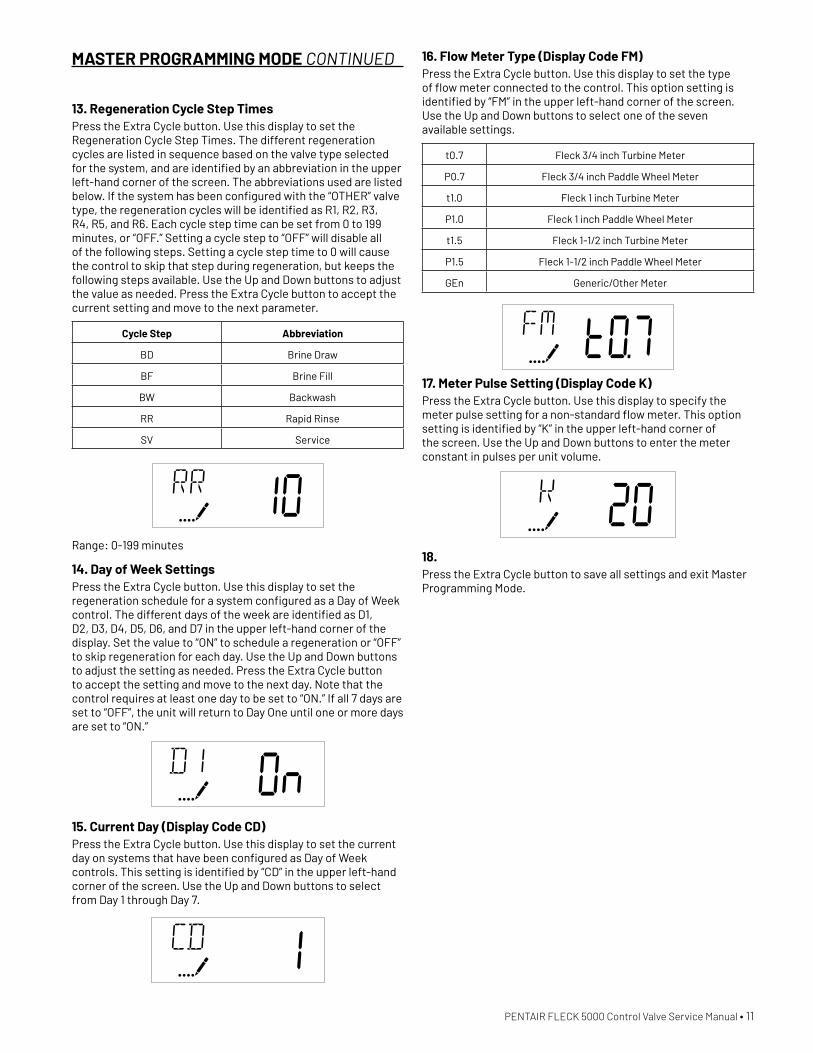
13. Regeneration Cycle Step TimesPress the Extra Cycle button. Use this display to set the Regeneration Cycle Step Times. The different regeneration cycles are listed in sequence based on the valve type selected for the system, and are identified by an abbreviation in the upper left-hand corner of the screen. The abbreviations used are listed below. If the system has been configured with the “OTHER” valve type, the regeneration cycles will be identified as R1, R2, R3, R4, R5, and R6. Each cycle step time can be set from 0 to 199 minutes, or “OFF.” Setting a cycle step to “OFF” will disable all of the following steps. Setting a cycle step time to 0 will cause the control to skip that step during regeneration, but keeps the following steps available. Use the Up and Down buttons to adjust the value as needed. Press the Extra Cycle button to accept the current setting and move to the next parameter.
Cycle Step Abbreviation
BD Brine Draw
BF Brine Fill
BW Backwash
RR Rapid Rinse
SV Service
Range: 0-199 minutes
14. Day of Week SettingsPress the Extra Cycle button. Use this display to set the regeneration schedule for a system configured as a Day of Week control. The different days of the week are identified as D1, D2, D3, D4, D5, D6, and D7 in the upper left-hand corner of the display. Set the value to “ON” to schedule a regeneration or “OFF” to skip regeneration for each day. Use the Up and Down buttons to adjust the setting as needed. Press the Extra Cycle button to accept the setting and move to the next day. Note that the control requires at least one day to be set to “ON.” If all 7 days are set to “OFF”, the unit will return to Day One until one or more days are set to “ON.”
15. Current Day (Display Code CD)Press the Extra Cycle button. Use this display to set the current day on systems that have been configured as Day of Week controls. This setting is identified by “CD” in the upper left-hand corner of the screen. Use the Up and Down buttons to select from Day 1 through Day 7.
MASTER PROGRAMMING MODE CONTINUED 16. Flow Meter Type (Display Code FM)Press the Extra Cycle button. Use this display to set the type of flow meter connected to the control. This option setting is identified by “FM” in the upper left-hand corner of the screen. Use the Up and Down buttons to select one of the seven available settings.
t0.7 Fleck 3/4 inch Turbine Meter
P0.7 Fleck 3/4 inch Paddle Wheel Meter
t1.0 Fleck 1 inch Turbine Meter
P1.0 Fleck 1 inch Paddle Wheel Meter
t1.5 Fleck 1-1/2 inch Turbine Meter
P1.5 Fleck 1-1/2 inch Paddle Wheel Meter
GEn Generic/Other Meter
17. Meter Pulse Setting (Display Code K)Press the Extra Cycle button. Use this display to specify the meter pulse setting for a non-standard flow meter. This option setting is identified by “K” in the upper left-hand corner of the screen. Use the Up and Down buttons to enter the meter constant in pulses per unit volume.
18. Press the Extra Cycle button to save all settings and exit Master Programming Mode.
12 • PENTAIR FLECK 5000 Control Valve Service Manual
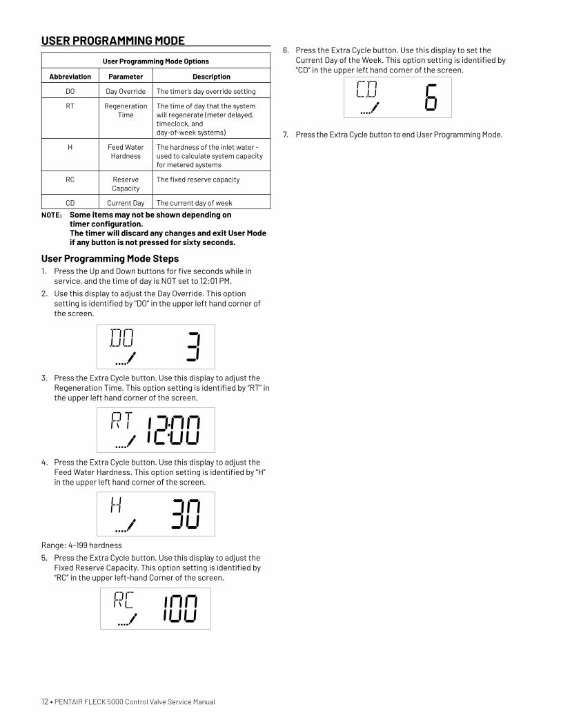
USER PROGRAMMING MODE
User Programming Mode Options
Abbreviation Parameter Description
DO Day Override The timer’s day override setting
RT Regeneration Time
The time of day that the system will regenerate (meter delayed, timeclock, and day-of-week systems)
H Feed Water Hardness
The hardness of the inlet water - used to calculate system capacity for metered systems
RC Reserve Capacity
The fixed reserve capacity
CD Current Day The current day of week
NOTE: Some items may not be shown depending on timer configuration. The timer will discard any changes and exit User Mode if any button is not pressed for sixty seconds.
User Programming Mode Steps1. Press the Up and Down buttons for five seconds while in
service, and the time of day is NOT set to 12:01 PM.
2. Use this display to adjust the Day Override. This option setting is identified by “DO” in the upper left hand corner of the screen.
3. Press the Extra Cycle button. Use this display to adjust the Regeneration Time. This option setting is identified by “RT” in the upper left hand corner of the screen.
4. Press the Extra Cycle button. Use this display to adjust the Feed Water Hardness. This option setting is identified by “H” in the upper left hand corner of the screen.
Range: 4-199 hardness
5. Press the Extra Cycle button. Use this display to adjust the Fixed Reserve Capacity. This option setting is identified by “RC” in the upper left-hand Corner of the screen.
6. Press the Extra Cycle button. Use this display to set the Current Day of the Week. This option setting is identified by “CD” in the upper left hand corner of the screen.
7. Press the Extra Cycle button to end User Programming Mode.
PENTAIR FLECK 5000 Control Valve Service Manual • 13
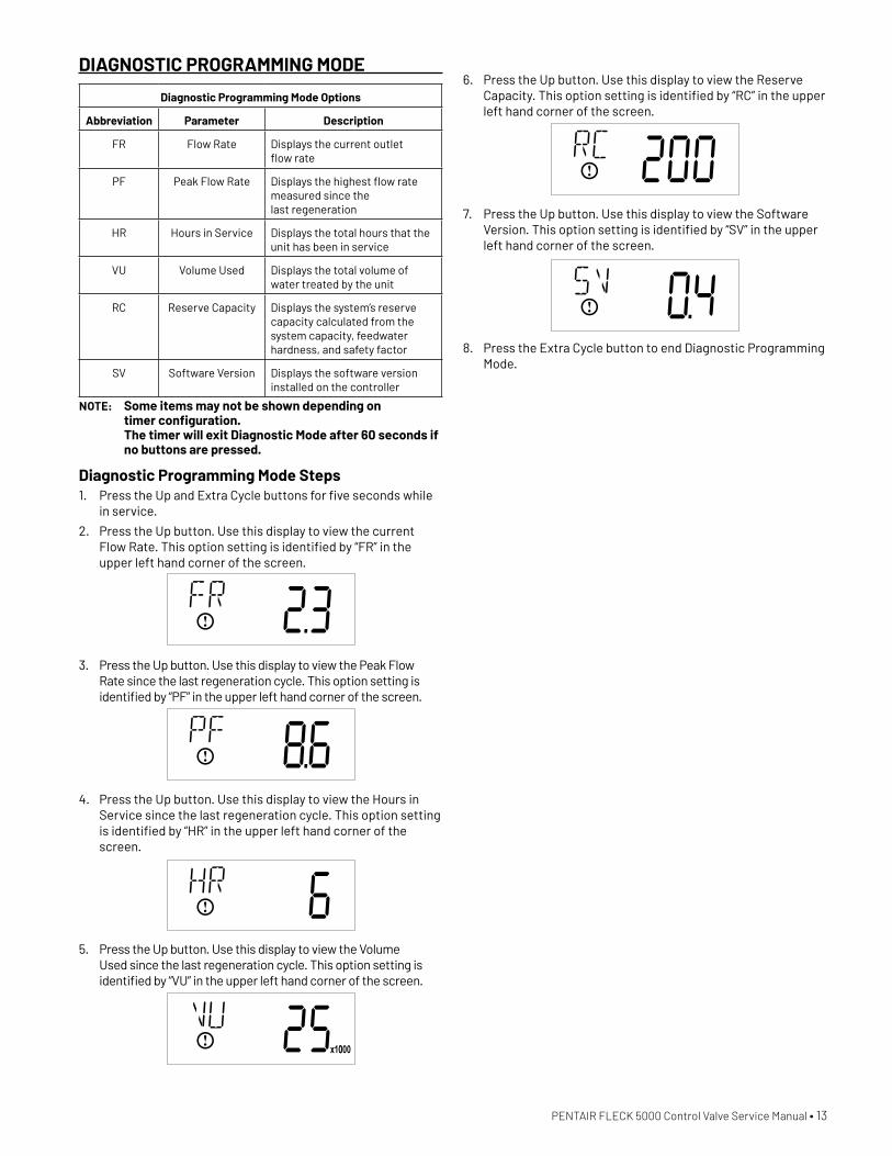
DIAGNOSTIC PROGRAMMING MODE
Diagnostic Programming Mode Options
Abbreviation Parameter Description
FR Flow Rate Displays the current outlet flow rate
PF Peak Flow Rate Displays the highest flow rate measured since the last regeneration
HR Hours in Service Displays the total hours that the unit has been in service
VU Volume Used Displays the total volume of water treated by the unit
RC Reserve Capacity Displays the system’s reserve capacity calculated from the system capacity, feedwater hardness, and safety factor
SV Software Version Displays the software version installed on the controller
NOTE: Some items may not be shown depending on timer configuration. The timer will exit Diagnostic Mode after 60 seconds if no buttons are pressed.
Diagnostic Programming Mode Steps1. Press the Up and Extra Cycle buttons for five seconds while
in service.
2. Press the Up button. Use this display to view the current Flow Rate. This option setting is identified by “FR” in the upper left hand corner of the screen.
3. Press the Up button. Use this display to view the Peak Flow Rate since the last regeneration cycle. This option setting is identified by “PF” in the upper left hand corner of the screen.
4. Press the Up button. Use this display to view the Hours in Service since the last regeneration cycle. This option setting is identified by “HR” in the upper left hand corner of the screen.
5. Press the Up button. Use this display to view the Volume Used since the last regeneration cycle. This option setting is identified by “VU” in the upper left hand corner of the screen.
6. Press the Up button. Use this display to view the Reserve Capacity. This option setting is identified by “RC” in the upper left hand corner of the screen.
7. Press the Up button. Use this display to view the Software Version. This option setting is identified by “SV” in the upper left hand corner of the screen.
8. Press the Extra Cycle button to end Diagnostic Programming Mode.
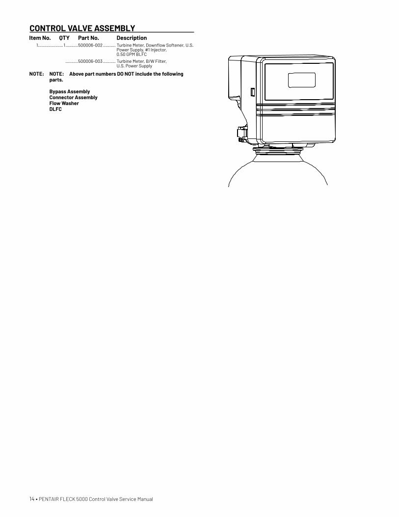
CONTROL VALVE ASSEMBLYItem No. QTY Part No. Description 1 .................... 1 ..........500006-002 .......... Turbine Meter, Downflow Softener, U.S.
Power Supply, #1 Injector, 0.50 GPM BLFC
..........500006-003 .......... Turbine Meter, B/W Filter, U.S. Power Supply
NOTE: NOTE: Above part numbers DO NOT include the following parts. Bypass Assembly Connector Assembly Flow Washer DLFC
14 • PENTAIR FLECK 5000 Control Valve Service Manual

CONTROL VALVE ASSEMBLY
1
23
45
6
7
8
9
10
11
12
13
14
15
16
17
18
19
20
21
22
23
24
B
A
134 2
TITLE
SIZE
SCALE SHEET 1 OF 1
DWG NO. REV
CHECKED
APPROVED
APPROVALS DATE
THIRD ANGLEPROJECTION
DRAWN VALVE / POWERHEAD ASSY 50DP AC SXTSOFTENER
61500-50DP AC SXTD1:5
PS
5
D
C
678
678
B
C
D
B
A
DO NOT SCALE DRAWING. DIMS. ARE IN INCHES [mm]INTERPRET DIMS AND TOLERANCES PER ASME Y14.5M -2009UNLESS OTHERWISE SPECIFIED:ALL FINISHED MACHINED SURFACES 125 OR BETTER.TOLERANCES: ANGLES : 1 1 PLACE .X: .015 [0.38] 2 PLACE .XX: .01 [0.3] 3 PLACE .XXX: .005 [0.13]
BR42889
12/10/2019
Pentair ResidentialFiltration, LLC
THIS DOCUMENT IS SOLELY THE PROPERTY OF PENTAIRRESIDENTIAL FILTRATION, LLC. REPRODUCTION, USE DISCLOSURE, OR TRANSMISSION OF THIS DOCUMENT ORDETAILS CONTAINED HEREIN, IN PART OR IN WHOLE, IS PROHIBITED WITHOUT THE WRITTEN CONSENT OF PENTAIR RESIDENTIAL FILTRATION, LLC ENGINEERING. THIS DOCUMENT AND ANY COPIES SHALL BE RETURNED TOPENTAIR RESIDENTIAL FILTRATION, LLC UPON REQUEST.
COMPONENTS / ASSEMBLIES TO BE COMPLIANT AND COMPATIBLE WITH EUROPEAN UNION DIRECTIVE 2011/65/EEC (RoHS2) & REGULATION (EC)1907/2006 (REACH) REQUIREMENTS
Item No. QTY Part No. Description 1 �������������������� 1 ����������18815 ��������������������� Valve Body Assy, 5000,
1-inch Dist Down Flow
2 ������������������� 1 ����������18271 ��������������������� Screen Injector, 5800
3 ������������������� 1 ����������40064 ������������������� Seal Injector
4 ������������������� 1 ����������18277 ��������������������� Cap Injector
5 �������������������2 ���������18262��������������������� Screw, Hex Washer Head, #10-24 x 1�00
6 ������������������� 1 ����������19654��������������������� Label, 0�125 gpm Brine Flow
����������12128 ��������������������� Label, 0�25 gpm BLFC
����������10759 ��������������������� Label, 0�5 gpm 1�5 lbs Salt/Min
����������10760 �������������������� Label, 1�0 gpm 3 lbs Salt/Min
7 ������������������� 1 ����������13333 ��������������������� Label, Injector, Blank
8 �������������������3 ���������18261 ��������������������� Screw, Hex Washer Head, #10-24 0�81
9 ������������������� 1 ����������13304 �������������������� O-ring, -121
10 ����������������� 1 ����������18303-01 ���������������� O-ring, -336, 560CD
11 ������������������ 1 ����������13030 �������������������� Retainer, Distributor Tube O-ring
12 ������������������ 1 ����������18569 ��������������������� Retainer, Tank Seal
13 ������������������ 1 ����������18312 ��������������������� DLFC Housing Retainer Clip
14������������������ 1 ����������60115-001 �������������� Piston Assy, 5000, Std, D/F
15������������������5 ����������44549 �������������������� Seal, Piston, 5000
16������������������4 ����������14241 ��������������������� Spacer, 5600
17������������������ 1 ����������18264 �������������������� Spacer End, 5000
18 ������������������ 1 ����������60032 �������������������� Brine Valve, 4600/5600
19 ������������������ 1 ����������13302 �������������������� O-ring, -014
20 �����������������������������60022-12 ��������������� BLFC, 0�125 gpm
����������60022-25 �������������� BLFC, 0�25 gpm
����������60022-50 �������������� BLFC, 0�5 gpm
����������60022-100 ������������� BLFC, 1�0 gpm
21��������������������� ���������60705-00 �������������� DLFC, Plastic, Blank
����������60706-8�0 �������������� DLFC, QC x 3/4"F, 8�0 GPM
����������60706-9�0 �������������� DLFC, QC x 3/4"F, 9�0 GPM
����������60706-10 ��������������� DLFC, QC x 3/4"F, 10 GPM
����������60706-12 ��������������� DLFC, QC x 3/4"F, 12 GPM
����������60706-15 ��������������� DLFC, QC x 3/4"F, 15 GPM
22 �����������������������������19153 ��������������������� Washer, Flow, 0�6 GPM
����������19152 ��������������������� Washer, Flow, 0�8 GPM
����������12085 �������������������� Washer, Flow, 1�2 GPM
����������19150 ��������������������� Washer, Flow, 1�3 GPM
����������12086 �������������������� Washer, Flow, 1�5 GPM
����������12087 ��������������������� Washer, Flow, 2�0 GPM
����������12088 �������������������� Washer, Flow, 2�4 GPM
����������12089 �������������������� Washer, Flow, 3�0 GPM
����������12090 �������������������� Washer, Flow, 3�5 GPM
����������12091 ��������������������� Washer, Flow, 4�0 GPM
����������19147 ��������������������� Washer, Flow, 4�5 GPM
����������12092 �������������������� Washer, Flow, 5�0 GPM
����������17814 ��������������������� Washer, Flow, 6�0 GPM
����������12408 �������������������� Washer, Flow, 7�0 GPM
23 �����������������������������18272-000 ������������� Injector Assy, 1610, #000, Brown
����������18272-00 ��������������� Injector Assy, 1610, #00, Violet
����������18272-0 ����������������� Injector Assy, 1610, #0, Red
����������18272-1 ������������������ Injector Assy, 1610, #1, White
����������18272-2 ����������������� Injector Assy, 1610, #2, Blue
����������18272-3 ����������������� Injector Assy, 1610, #3, Yellow
24 �����������������������������18276-01 ���������������� Injector Assy, Plug, w/O-rings
Not Shown: ����������40947-01 ��������������� Plug, Brine Valve, w/O-ring, 560CD
����������13918-01 ����������������� BLFC Module Plug Assy, w/O-ring
Excessive side load on piston rod may cause premature failure.
If seal/spacer stack is stuck in valve bore during disassembly, rotate stack prior to removal.
CAUTION
CAUTION
PENTAIR FLECK 5000 Control Valve Service Manual • 15
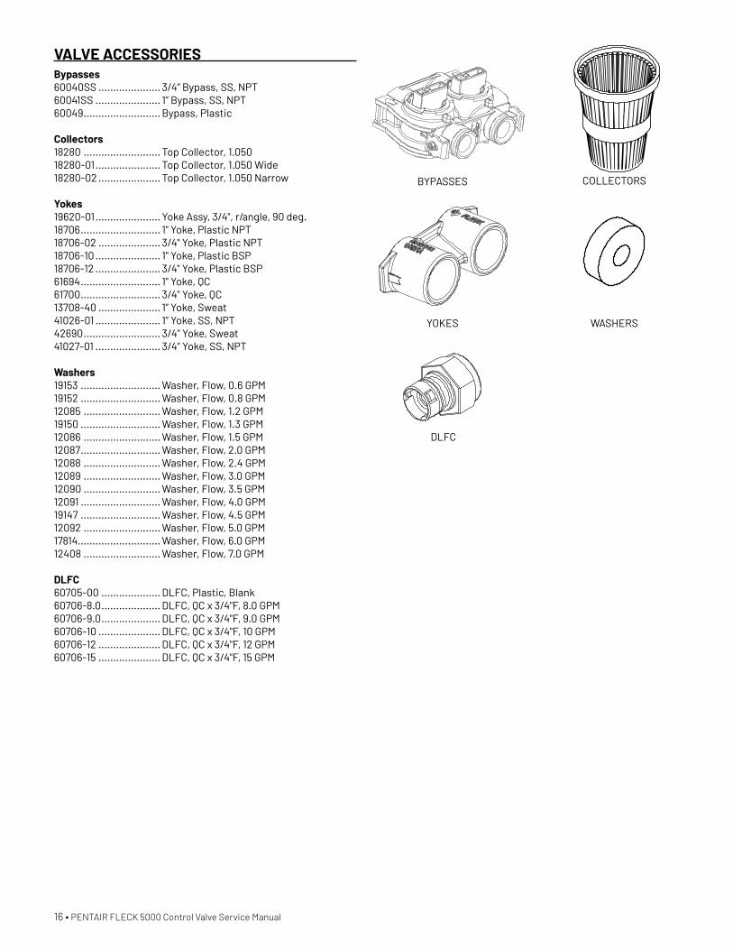
VALVE ACCESSORIESBypasses60040SS ..................... 3/4” Bypass, SS, NPT60041SS ...................... 1” Bypass, SS, NPT60049 .......................... Bypass, Plastic
Collectors18280 .......................... Top Collector, 1.05018280-01 ...................... Top Collector, 1.050 Wide18280-02 ..................... Top Collector, 1.050 Narrow
Yokes19620-01 ...................... Yoke Assy, 3/4", r/angle, 90 deg.18706 ........................... 1" Yoke, Plastic NPT18706-02 ..................... 3/4" Yoke, Plastic NPT18706-10 ...................... 1" Yoke, Plastic BSP18706-12 ...................... 3/4" Yoke, Plastic BSP61694 ........................... 1" Yoke, QC61700 ........................... 3/4" Yoke, QC13708-40 ..................... 1” Yoke, Sweat41026-01 ...................... 1” Yoke, SS, NPT42690 .......................... 3/4” Yoke, Sweat41027-01 ...................... 3/4” Yoke, SS, NPT
Washers19153 ........................... Washer, Flow, 0.6 GPM19152 ........................... Washer, Flow, 0.8 GPM12085 .......................... Washer, Flow, 1.2 GPM19150 ........................... Washer, Flow, 1.3 GPM12086 .......................... Washer, Flow, 1.5 GPM12087 ........................... Washer, Flow, 2.0 GPM12088 .......................... Washer, Flow, 2.4 GPM12089 .......................... Washer, Flow, 3.0 GPM12090 .......................... Washer, Flow, 3.5 GPM12091 ........................... Washer, Flow, 4.0 GPM19147 ........................... Washer, Flow, 4.5 GPM12092 .......................... Washer, Flow, 5.0 GPM17814............................ Washer, Flow, 6.0 GPM12408 .......................... Washer, Flow, 7.0 GPM
DLFC60705-00 .................... DLFC, Plastic, Blank60706-8.0 .................... DLFC, QC x 3/4"F, 8.0 GPM60706-9.0 .................... DLFC, QC x 3/4"F, 9.0 GPM60706-10 ..................... DLFC, QC x 3/4"F, 10 GPM60706-12 ..................... DLFC, QC x 3/4"F, 12 GPM60706-15 ..................... DLFC, QC x 3/4"F, 15 GPM
COLLECTORS
WASHERS
BYPASSES
YOKES
DLFC
16 • PENTAIR FLECK 5000 Control Valve Service Manual
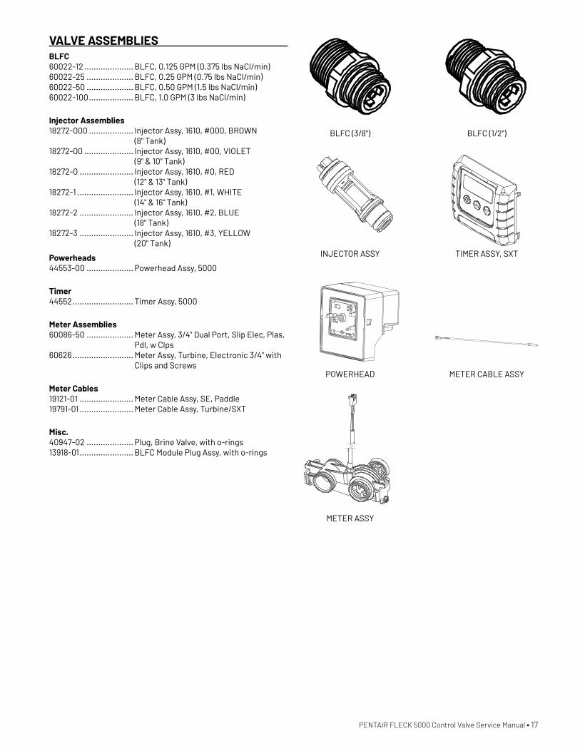
VALVE ASSEMBLIESBLFC60022-12 ..................... BLFC, 0.125 GPM (0.375 lbs NaCl/min)60022-25 .................... BLFC, 0.25 GPM (0.75 lbs NaCl/min)60022-50 .................... BLFC, 0.50 GPM (1.5 lbs NaCl/min)60022-100 ................... BLFC, 1.0 GPM (3 lbs NaCl/min)
Injector Assemblies18272-000 ................... Injector Assy, 1610, #000, BROWN
(8" Tank)18272-00 ..................... Injector Assy, 1610, #00, VIOLET
(9" & 10" Tank)18272-0 ....................... Injector Assy, 1610, #0, RED
(12" & 13" Tank)18272-1 ........................ Injector Assy, 1610, #1, WHITE
(14" & 16" Tank)18272-2 ....................... Injector Assy, 1610, #2, BLUE
(18" Tank)18272-3 ....................... Injector Assy, 1610, #3, YELLOW
(20" Tank)
Powerheads44553-00 .................... Powerhead Assy, 5000
Timer44552 .......................... Timer Assy, 5000
Meter Assemblies60086-50 .................... Meter Assy, 3/4" Dual Port, Slip Elec, Plas,
Pdl, w Clps60626 .......................... Meter Assy, Turbine, Electronic 3/4" with
Clips and Screws
Meter Cables19121-01 ....................... Meter Cable Assy, SE, Paddle19791-01 ....................... Meter Cable Assy, Turbine/SXT
Misc.40947-02 .................... Plug, Brine Valve, with o-rings13918-01 ....................... BLFC Module Plug Assy, with o-rings
B
A
12
TITLE
SIZE
SCALE SHEET 1 OF 1
DWG NO. REV
Pentair ResidentialFiltration, LLC
APPROVED
APPROVALS DATE
THIRD ANGLEPROJECTION
DRAWN INJECTOR ASSY, #1, WHITE5000/5800
18272-1A2:1
REVISIONSDATE APP'DDESCRIPTIONREV.PCOZONE
B
2 1
F
A
DO NOT SCALE DRAWING. DIMS. ARE IN INCHES [mm]INTERPRET DIMS AND TOLERANCES PER ASME Y14.5M -2009UNLESS OTHERWISE SPECIFIED:ALL FINISHED MACHINED SURFACES 125 OR BETTER.TOLERANCES: ANGLES : 1 1 PLACE .X: .015 [0.38] 2 PLACE .XX: .01 [0.3] 3 PLACE .XXX: .005 [0.13]
BR42886
THIS DOCUMENT IS SOLELY THE PROPERTY OF PENTAIRRESIDENTIAL FILTRATION, LLC. REPRODUCTION, USE DISCLOSURE, OR TRANSMISSION OF THIS DOCUMENT ORDETAILS CONTAINED HEREIN, IN PART OR IN WHOLE, IS PROHIBITED WITHOUT THE WRITTEN CONSENT OF PENTAIR RESIDENTIAL FILTRATION, LLC ENGINEERING. THIS DOCUMENT AND ANY COPIES SHALL BE RETURNED TOPENTAIR RESIDENTIAL FILTRATION, LLC UPON REQUEST.
COMPONENTS / ASSEMBLIES TO BE COMPLIANT AND COMPATIBLE WITH EUROPEAN UNION DIRECTIVE 2011/65/EEC (RoHS2) & REGULATION (EC)1907/2006 (REACH) REQUIREMENT
CHECKED
20
16
13
14
14
15
15
11
10
9
2
5
12
8
4
3
2
1
6
17
18
7
272481 A RELEASE FOR PRE-PRODUCTION
44553-005000
44553-0150DP
12-9-12 PWS
ITEM NO. PART NUMBER DESCRIPTION 44553-
00/QTY.44553-
01/QTY.1 BR14044 TIE, CABLE, PLASTIC 1 1
2 13296 SCREW, HEX WASHER, 6-20 X 1/2 5 5
3 18259-02 COVER,BACK,BLACK 1 1
4 13602 SCREW,PHIL RD HD,6-32 X 5/16 2 2
5 13547 STRAIN RELIEF, ROUND CORD 1 16 19474 HARNESS,POWER,5600SE,ELECT 1 -7 19474-01 HARNESS, POWER,8500SE/4200SE - 1
8 40251 MOTOR, 24V - 50/60HZ 1 1
9 18202 BACK PLATE 1 1
10 18228 CAM, BRINE VALVE 1 1
11 18211-01 GEAR, MAIN, DOWNFLOW, MACHD 1 1
12 18655 PIN,ROLL,3/32 X 1/2 1 1
13 19927 CAM, RAYNE, D/F, SE 1 1
14 10218 2 2
15 17876 SCREW,PHIL PAN,4-40X1 1/8 2 2
16 40269 PLATE,FRONT 1 1
17 40422 NUT, WIRE, TAN 4 4
18 44147 TRANSFORMER, 24V,9.6VA 1 1
19 BR16618 BAG, POLY, 8"X4"X12", 1.5 MIL 1 1
20 40326 LABEL,COVER-UP,PROFLOSE 1 -
B
A
134
4 3 2 1
2
TITLE
SIZE
SCALE SHEET 1 OF 1
DWG NO. REV
CHECKED
APPROVED
APPROVALS DATE
THIRD ANGLEPROJECTION
DRAWN PWRHD ASSY, 5000 AC-SXT
44553D1:8
PS
5
5
D
C
678
678
B
C
D
REVISIONSDATE APP'DDESCRIPTIONREV.PCOZONE
A.01
A
DO NOT SCALE DRAWING. DIMS. ARE IN INCHES [mm]INTERPRET DIMS AND TOLERANCES PER ASME Y14.5M -2009UNLESS OTHERWISE SPECIFIED:ALL FINISHED MACHINED SURFACES 125 OR BETTER.TOLERANCES: ANGLES : 1 1 PLACE .X: .015 [0.38] 2 PLACE .XX: .01 [0.3] 3 PLACE .XXX: .005 [0.13]
BR42889
12/10/2019
Pentair ResidentialFiltration, LLC
THIS DOCUMENT IS SOLELY THE PROPERTY OF PENTAIRRESIDENTIAL FILTRATION, LLC. REPRODUCTION, USE DISCLOSURE, OR TRANSMISSION OF THIS DOCUMENT ORDETAILS CONTAINED HEREIN, IN PART OR IN WHOLE, IS PROHIBITED WITHOUT THE WRITTEN CONSENT OF PENTAIR RESIDENTIAL FILTRATION, LLC ENGINEERING. THIS DOCUMENT AND ANY COPIES SHALL BE RETURNED TOPENTAIR RESIDENTIAL FILTRATION, LLC UPON REQUEST.
COMPONENTS / ASSEMBLIES TO BE COMPLIANT AND COMPATIBLE WITH EUROPEAN UNION DIRECTIVE 2011/65/EEC (RoHS2) & REGULATION (EC)1907/2006 (REACH) REQUIREMENTS
272481 A RELESE FOR PRE-PRODUCTION 12-9-19 PWS
ITEM NO. PART NUMBER DESCRIPTION QTY.
1 BR42635-01 1
2 BR42637 LABEL, DISPLAY,SE 1
3 44098U CIRCUIT BOARD, SXT AC, UNPRGM 1
B
A
B
134
4 3 2 1
2
TITLE
SIZE
SCALE SHEET 1 OF 1
DWG NO. REV
Pentair ResidentialFiltration, LLC
CHECKED
APPROVED
APPROVALS DATE
THIRD ANGLEPROJECTION
DRAWN TIMER ASSY, AC-SXT 5000
44552B1:2
PS
REVISIONS
DATE APP'DDESCRIPTIONREV.PCOZONE
A.01
A
DO NOT SCALE DRAWING. DIMS. ARE IN INCHES [mm]INTERPRET DIMS AND TOLERANCES PER ASME Y14.5M -2009UNLESS OTHERWISE SPECIFIED:ALL FINISHED MACHINED SURFACES 125 OR BETTER.TOLERANCES:
ANGLES : 1 1 PLACE .X: .015 [0.38] 2 PLACE .XX: .01 [0.3] 3 PLACE .XXX: .005 [0.13]
BR42887
12/10/2019
THIS DOCUMENT IS SOLELY THE PROPERTY OF PENTAIRRESIDENTIAL FILTRATION, LLC. REPRODUCTION, USE DISCLOSURE, OR TRANSMISSION OF THIS DOCUMENT ORDETAILS CONTAINED HEREIN, IN PART OR IN WHOLE, IS PROHIBITED WITHOUT THE WRITTEN CONSENT OF PENTAIR RESIDENTIAL FILTRATION, LLC ENGINEERING. THIS DOCUMENT AND ANY COPIES SHALL BE RETURNED TOPENTAIR RESIDENTIAL FILTRATION, LLC UPON REQUEST.
COMPONENTS / ASSEMBLIES TO BE COMPLIANT AND COMPATIBLE WITH EUROPEAN UNION DIRECTIVE 2011/65/EEC (RoHS2) & REGULATION (EC)1907/2006 (REACH) REQUIREMENTS
BLFC (3/8")
INJECTOR ASSY
POWERHEAD
METER ASSY
BLFC (1/2")
TIMER ASSY, SXT
METER CABLE ASSY
PENTAIR FLECK 5000 Control Valve Service Manual • 17
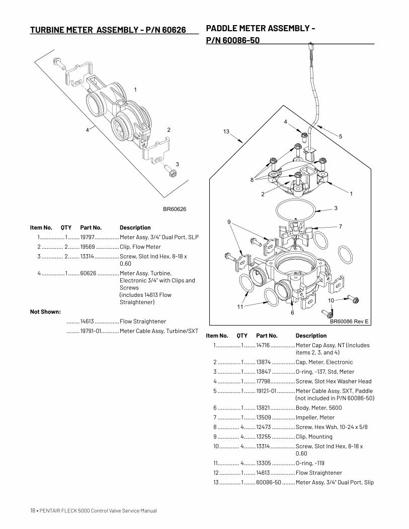
TURBINE METER ASSEMBLY - P/N 60626
Item No. QTY Part No. Description
1 ...............1 ....... 19797 ...............Meter Assy, 3/4" Dual Port, SLP
2 ............. 2 ....... 19569 ..............Clip, Flow Meter
3 ............. 2 ....... 13314 ...............Screw, Slot Ind Hex, 8-18 x 0.60
4 ..............1 ....... 60626 .............Meter Assy, Turbine, Electronic 3/4" with Clips and Screws (includes 14613 Flow Straightener)
Not Shown:
........ 14613 ...............Flow Straightener
........ 19791-01...........Meter Cable Assy, Turbine/SXT
BR60626
1
2
3
4
PADDLE METER ASSEMBLY - P/N 60086-50
Item No. QTY Part No. Description
1 ...............1 ....... 14716 ...............Meter Cap Assy, NT (includes items 2, 3, and 4)
2 ..............1 ....... 13874 ..............Cap, Meter, Electronic
3 ..............1 ....... 13847 ..............O-ring, -137, Std, Meter
4 ..............1 ....... 17798 ...............Screw, Slot Hex Washer Head
5 ..............1 ....... 19121-01 ...........Meter Cable Assy, SXT, Paddle (not included in P/N 60086-50)
6 ..............1 ....... 13821 ...............Body, Meter, 5600
7 ..............1 ....... 13509 .............. Impeller, Meter
8 ............. 4 ....... 12473 ..............Screw, Hex Wsh, 10-24 x 5/8
9 ............. 4 ....... 13255 ..............Clip, Mounting
10 ............ 4 ....... 13314 ...............Screw, Slot Ind Hex, 8-18 x 0.60
11 ............. 4 ....... 13305 ..............O-ring, -119
12 .............1 ....... 14613 ...............Flow Straightener
13 .............1 ....... 60086-50 ........Meter Assy, 3/4" Dual Port, Slip
5
8
12
7
6
9
10
3
4
11
13
BR60086 Rev E
18 • PENTAIR FLECK 5000 Control Valve Service Manual
23
6
BR60049 Rev H
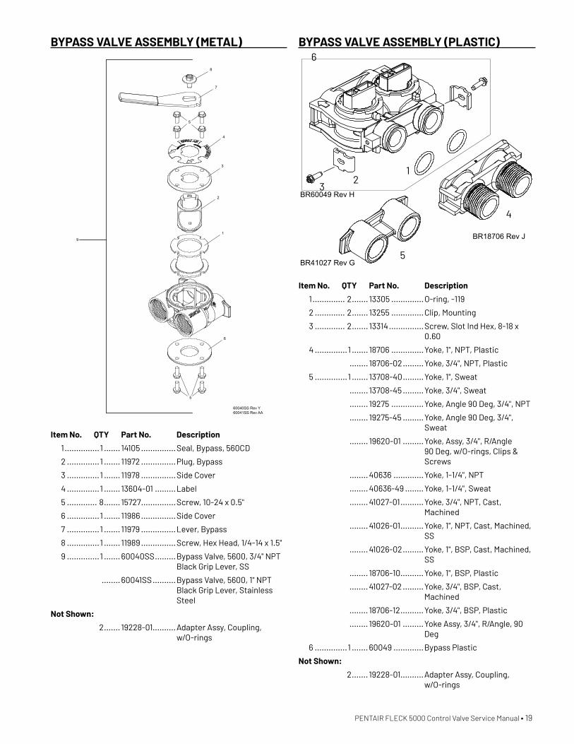
BYPASS VALVE ASSEMBLY (PLASTIC)
Item No. QTY Part No. Description
1 .............. 2 ....... 13305 ..............O-ring, -119
2 ............. 2 ....... 13255 ..............Clip, Mounting
3 ............. 2 ....... 13314 ...............Screw, Slot Ind Hex, 8-18 x 0.60
4 ..............1 ....... 18706 ..............Yoke, 1", NPT, Plastic
........ 18706-02 .........Yoke, 3/4", NPT, Plastic
5 ..............1 ....... 13708-40 .........Yoke, 1", Sweat
........ 13708-45 .........Yoke, 3/4", Sweat
........ 19275 ..............Yoke, Angle 90 Deg, 3/4", NPT
........ 19275-45 .........Yoke, Angle 90 Deg, 3/4", Sweat
........ 19620-01 .........Yoke, Assy, 3/4", R/Angle 90 Deg, w/O-rings, Clips & Screws
........ 40636 .............Yoke, 1-1/4", NPT
........ 40636-49 ........Yoke, 1-1/4", Sweat
........ 41027-01 ..........Yoke, 3/4", NPT, Cast, Machined
........ 41026-01 ..........Yoke, 1", NPT, Cast, Machined, SS
........ 41026-02 .........Yoke, 1", BSP, Cast, Machined, SS
........ 18706-10 ..........Yoke, 1", BSP, Plastic
........ 41027-02 .........Yoke, 3/4", BSP, Cast, Machined
........ 18706-12 ..........Yoke, 3/4", BSP, Plastic
........ 19620-01 .........Yoke Assy, 3/4", R/Angle, 90 Deg
6 ..............1 ....... 60049 .............Bypass Plastic
Not Shown:
2 ....... 19228-01..........Adapter Assy, Coupling, w/O-rings
1
4
5
BR18706 Rev J
BR41027 Rev G
BYPASS VALVE ASSEMBLY (METAL)
Item No. QTY Part No. Description
1 ...............1 ....... 14105 ...............Seal, Bypass, 560CD
2 ..............1 ....... 11972 ...............Plug, Bypass
3 ..............1 ....... 11978 ...............Side Cover
4 ..............1 ....... 13604-01 .........Label
5 ............. 8 ....... 15727 ...............Screw, 10-24 x 0.5"
6 ..............1 ....... 11986 ...............Side Cover
7 ..............1 ....... 11979 ...............Lever, Bypass
8 ..............1 ....... 11989 ...............Screw, Hex Head, 1/4-14 x 1.5"
9 ..............1 ....... 60040SS .........Bypass Valve, 5600, 3/4" NPT Black Grip Lever, SS
........ 60041SS ..........Bypass Valve, 5600, 1" NPT Black Grip Lever, Stainless Steel
Not Shown:
2 ....... 19228-01..........Adapter Assy, Coupling, w/O-rings
8
7
5
4
3
2
1
6
5
9
60040SS Rev Y60041SS Rev AA
PENTAIR FLECK 5000 Control Valve Service Manual • 19
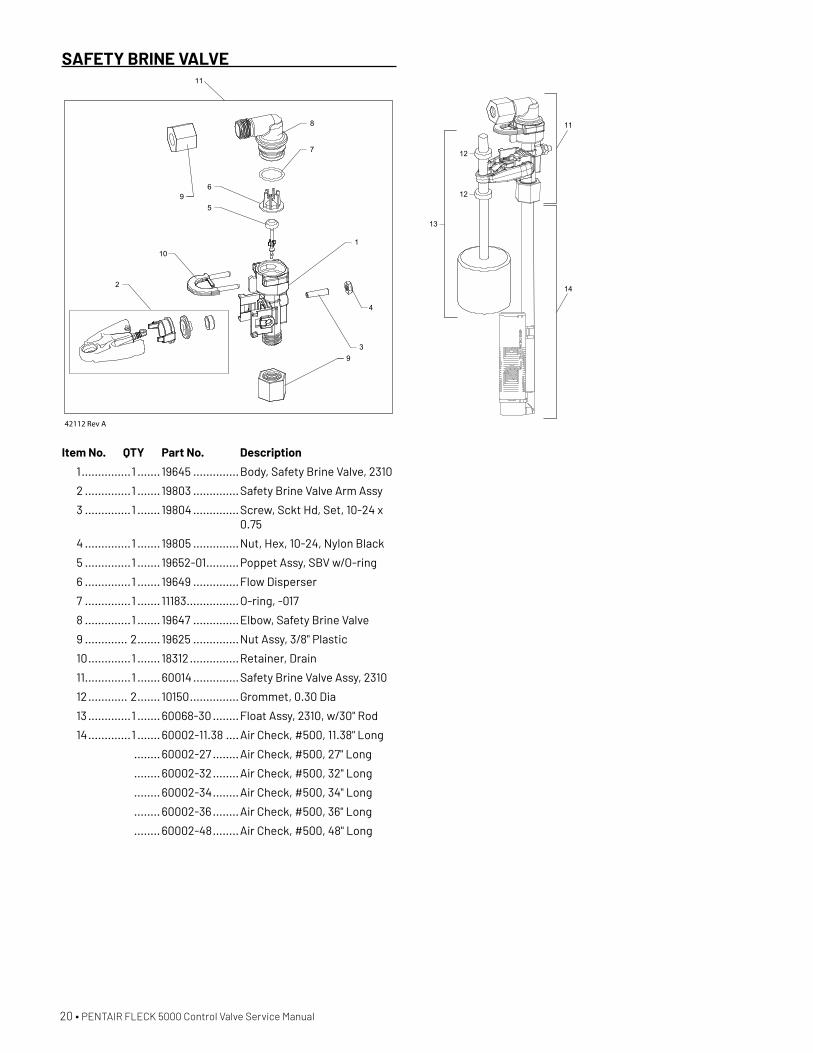
SAFETY BRINE VALVE
Item No. QTY Part No. Description
1 ...............1 ....... 19645 ..............Body, Safety Brine Valve, 2310
2 ..............1 ....... 19803 ..............Safety Brine Valve Arm Assy
3 ..............1 ....... 19804 ..............Screw, Sckt Hd, Set, 10-24 x 0.75
4 ..............1 ....... 19805 ..............Nut, Hex, 10-24, Nylon Black
5 ..............1 ....... 19652-01 ..........Poppet Assy, SBV w/O-ring
6 ..............1 ....... 19649 ..............Flow Disperser
7 ..............1 ....... 11183 ................O-ring, -017
8 ..............1 ....... 19647 ..............Elbow, Safety Brine Valve
9 ............. 2 ....... 19625 ..............Nut Assy, 3/8" Plastic
10 .............1 ....... 18312 ...............Retainer, Drain
11 ..............1 ....... 60014 ..............Safety Brine Valve Assy, 2310
12 ............ 2 ....... 10150 ...............Grommet, 0.30 Dia
13 .............1 ....... 60068-30 ........Float Assy, 2310, w/30" Rod
14 .............1 ....... 60002-11.38 ....Air Check, #500, 11.38" Long
........ 60002-27 ........Air Check, #500, 27" Long
........ 60002-32 ........Air Check, #500, 32" Long
........ 60002-34 ........Air Check, #500, 34" Long
........ 60002-36 ........Air Check, #500, 36" Long
........ 60002-48 ........Air Check, #500, 48" Long
9
8
6
5
110
3
4
9
2
7
42112 Rev A
11
11
12
14
12
13
20 • PENTAIR FLECK 5000 Control Valve Service Manual

DIMENSIONAL DRAWINGS
PENTAIR FLECK 5000 Control Valve Service Manual • 21

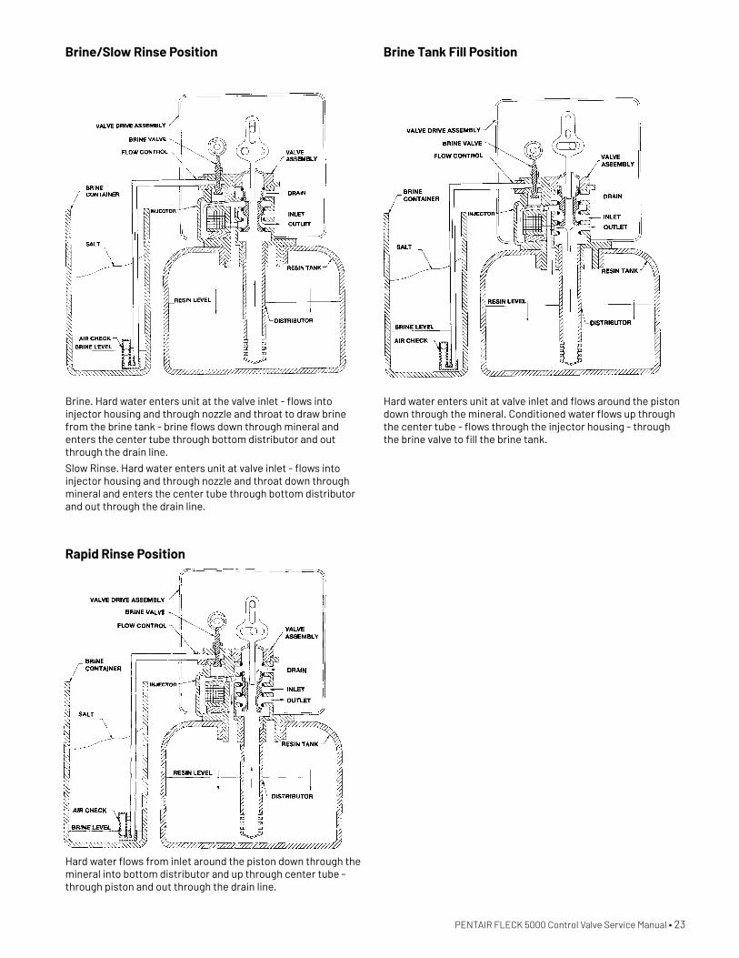
WATER CONDITIONER FLOW DIAGRAMS
22 • PENTAIR FLECK 5000 Control Valve Service Manual
Hard water enters unit at valve inlet and flows around the piston down through the mineral in the mineral tank. Conditioned water enters center tube through the bottom distributor then flows up through the center tube and to the outlet of the valve.
Hard water enters unit at valve inlet - flows around piston - down center tube - through bottom distributor and up through the mineral - around the piston and out the drain line.
Service Position
Backwash Position
PENTAIR FLECK 5000 Control Valve Service Manual • 23
Brine. Hard water enters unit at the valve inlet - flows into injector housing and through nozzle and throat to draw brine from the brine tank - brine flows down through mineral and enters the center tube through bottom distributor and out through the drain line.
Slow Rinse. Hard water enters unit at valve inlet - flows into injector housing and through nozzle and throat down through mineral and enters the center tube through bottom distributor and out through the drain line.
Hard water flows from inlet around the piston down through the mineral into bottom distributor and up through center tube - through piston and out through the drain line.
Hard water enters unit at valve inlet and flows around the piston down through the mineral. Conditioned water flows up through the center tube - flows through the injector housing - through the brine valve to fill the brine tank.
Brine/Slow Rinse Position
Rapid Rinse Position
Brine Tank Fill Position
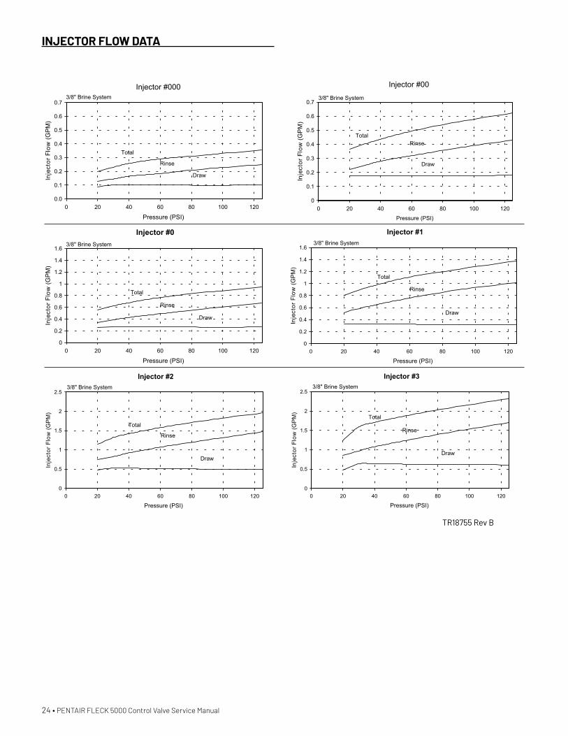
TR18755 Rev B
24 • PENTAIR FLECK 5000 Control Valve Service Manual
INJECTOR FLOW DATA
PENTAIR FLECK 5000 Control Valve Service Manual • 25
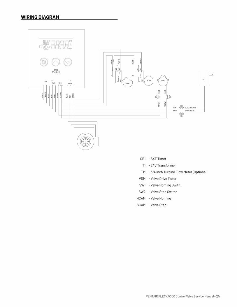
WIRING DIAGRAM
C
N.O
.
N.C
.SW
2
C
N.O
.
N.C
.SW
1
SCAM
VDM
TM
HCAM
PURP
LE
BLUE
YELL
OW
RED
T1
BLAC
K
BLAC
K
ORA
NGE
WT/
BLK
BLAC
K
WH
ITE
GREE
N BLUE
BLUE
WHITE
BLUE
WHITE (BLUE)
PURP
LE
ORA
NGE
BLAC
K
WT/
BLK
YELL
OW
BLACK (BROWN)
METERP1
S+-N N
H/SVDO
P2
N.O.H
PWR-HS
CB150/60 HZ
CB1 - SXT Timer
T1 - 24V Transformer
TM - 3/4 inch Turbine Flow Meter (Optional)
VDM - Valve Drive Motor
SW1 - Valve Homing Swith
SW2 - Valve Step Switch
HCAM - Valve Homing
SCAM - Valve Step

44555 REV B JN20
13845 BISHOPS DR. | SUITE 200BROOKFIELD, WI 53005 | UNITED STATES P: 262.238.4400 | CUSTOMER SERVICE: 800.279.9404 [email protected] | PENTAIR.COMAll indicated Pentair trademarks and logos are property of Pentair. Third party registered and unregistered trademarks and logos are the property of their respective owners.© 2020 Pentair. All rights reserved.
13845 BISHOPS DR. | SUITE 200BROOKFIELD, WI 53005 | UNITED STATES P: 262.238.4400 | CUSTOMER SERVICE: 800.279.9404 [email protected] | PENTAIR.COMAll indicated Pentair trademarks and logos are property of Pentair. Third party registered and unregistered trademarks and logos are the property of their respective owners.© 2020 Pentair. All rights reserved.
13845 BISHOPS DR. | SUITE 200BROOKFIELD, WI 53005 | UNITED STATES P: 262.238.4400 | CUSTOMER SERVICE: 800.279.9404 [email protected] | PENTAIR.COM§For a detailed list of where Pentair trademarks are registered, please visit pentair.com/registrations. Pentair trademarks and logos are owned by Pentair plc or its affiliates. Third party registered and unregistered trademarks and logos are the property of their respective owners. © 2020 Pentair. All rights reserved.
13845 BISHOPS DR. | SUITE 200BROOKFIELD, WI 53005 | UNITED STATES P: 262.238.4400 | CUSTOMER SERVICE: 800.279.9404 [email protected] | PENTAIR.COMAll indicated Pentair trademarks and logos are property of Pentair. Third party registered and unregistered trademarks and logos are the property of their respective owners.© 2020 Pentair. All rights reserved.
For Pentair Fleck Product Warranties visit: pentair.com/assets/residential-filtration-warranty


