Installation Instructions FLEX I/O Digital Input Modules Catalog numbers 1794-IB8, 1794-IB16, 1794-IB32 Table of Contents Topic Page Important User Information 2 Environment and Enclosure 3 Prevent Electrostatic Discharge 3 European Hazardous Location Approval 4 North American Hazardous Location Approval 6 Install Your Digital Input Module 8 Configure Your Input Module 14 Specifications 17
Transcript
Installation Instructions
FLEX I/O Digital Input ModulesCatalog numbers 1794-IB8, 1794-IB16, 1794-IB32
Table of Contents
Topic Page
Important User Information 2
Environment and Enclosure 3
Prevent Electrostatic Discharge 3
European Hazardous Location Approval 4
North American Hazardous Location Approval 6
Install Your Digital Input Module 8
Configure Your Input Module 14
Specifications 17
2 FLEX I/O Digital Input Modules
Important User Information
Solid-state equipment has operational characteristics differing from those of electromechanical equipment. Safety Guidelines for the Application, Installation, and Maintenance of Solid-State Controls (Publication SGI-1.1 available from your local Rockwell Automation Sales Office or online at http://www.rockwellautomation.com/literature/) describes some important differences between solid-state equipment and hard-wired electromechanical devices. Because of this difference, and also because of the wide variety of uses for solid-state equipment, all persons responsible for applying this equipment must satisfy themselves that each intended application of this equipment is acceptable.
In no event will Rockwell Automation, Inc. be responsible or liable for indirect or consequential damages resulting from the use or application of this equipment.
The examples and diagrams in this manual are included solely for illustrative purposes. Because of the many variables and requirements associated with any particular installation, Rockwell Automation, Inc. cannot assume responsibility or liability for actual use based on the examples and diagrams.
No patent liability is assumed by Rockwell Automation, Inc. with respect to use of information, circuits, equipment, or software described in this manual.
Reproduction of the contents of this manual, in whole or in part, without written permission of Rockwell Automation, Inc., is prohibited.
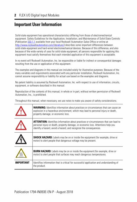
Throughout this manual, when necessary, we use notes to make you aware of safety considerations.
WARNING: Identifies information about practices or circumstances that can cause an explosion in a hazardous environment, which may lead to personal injury or death, property damage, or economic loss.
ATTENTION: Identifies information about practices or circumstances that can lead to personal injury or death, property damage, or economic loss. Attentions help you identify a hazard, avoid a hazard, and recognize the consequences.
SHOCK HAZARD: Labels may be on or inside the equipment (for example, drive or motor) to alert people that dangerous voltage may be present.
BURN HAZARD: Labels may be on or inside the equipment (for example, drive or motor) to alert people that surfaces may reach dangerous temperatures.
IMPORTANT Identifies information that is critical for successful application and understanding of the product.
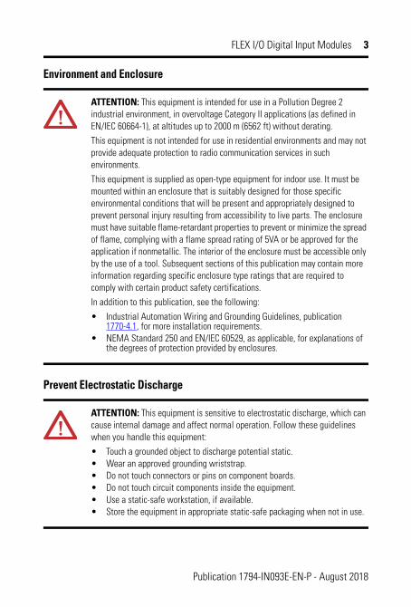
ATTENTION: This equipment is intended for use in a Pollution Degree 2 industrial environment, in overvoltage Category II applications (as defined in EN/IEC 60664-1), at altitudes up to 2000 m (6562 ft) without derating.
This equipment is not intended for use in residential environments and may not provide adequate protection to radio communication services in such environments.
This equipment is supplied as open-type equipment for indoor use. It must be mounted within an enclosure that is suitably designed for those specific environmental conditions that will be present and appropriately designed to prevent personal injury resulting from accessibility to live parts. The enclosure must have suitable flame-retardant properties to prevent or minimize the spread of flame, complying with a flame spread rating of 5VA or be approved for the application if nonmetallic. The interior of the enclosure must be accessible only by the use of a tool. Subsequent sections of this publication may contain more information regarding specific enclosure type ratings that are required to comply with certain product safety certifications.
In addition to this publication, see the following:
• Industrial Automation Wiring and Grounding Guidelines, publication 1770-4.1, for more installation requirements.
• NEMA Standard 250 and EN/IEC 60529, as applicable, for explanations of the degrees of protection provided by enclosures.
ATTENTION: This equipment is sensitive to electrostatic discharge, which can cause internal damage and affect normal operation. Follow these guidelines when you handle this equipment:
• Touch a grounded object to discharge potential static.• Wear an approved grounding wriststrap.• Do not touch connectors or pins on component boards.• Do not touch circuit components inside the equipment.• Use a static-safe workstation, if available.• Store the equipment in appropriate static-safe packaging when not in use.
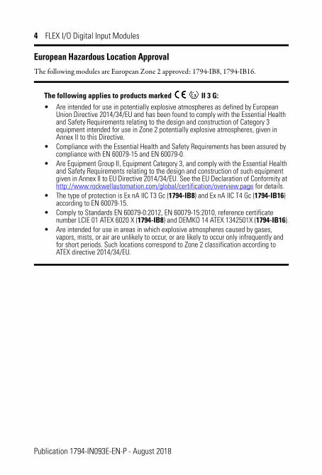
European Hazardous Location ApprovalThe following modules are European Zone 2 approved: 1794-IB8, 1794-IB16.
The following applies to products marked II 3 G:• Are intended for use in potentially explosive atmospheres as defined by European
Union Directive 2014/34/EU and has been found to comply with the Essential Health and Safety Requirements relating to the design and construction of Category 3 equipment intended for use in Zone 2 potentially explosive atmospheres, given in Annex II to this Directive.
• Compliance with the Essential Health and Safety Requirements has been assured by compliance with EN 60079-15 and EN 60079-0.
• Are Equipment Group II, Equipment Category 3, and comply with the Essential Health and Safety Requirements relating to the design and construction of such equipment given in Annex II to EU Directive 2014/34/EU. See the EU Declaration of Conformity at http://www.rockwellautomation.com/global/certification/overview.page for details.
• The type of protection is Ex nA IIC T3 Gc (1794-IB8) and Ex nA IIC T4 Gc (1794-IB16) according to EN 60079-15.
• Comply to Standards EN 60079-0:2012, EN 60079-15:2010, reference certificate number LCIE 01 ATEX 6020 X (1794-IB8) and DEMKO 14 ATEX 1342501X (1794-IB16).
• Are intended for use in areas in which explosive atmospheres caused by gases, vapors, mists, or air are unlikely to occur, or are likely to occur only infrequently and for short periods. Such locations correspond to Zone 2 classification according to ATEX directive 2014/34/EU.
WARNING: Special Conditions for Safe Use:• This equipment is not resistant to sunlight or other sources of UV radiation.• This equipment shall be mounted in an ATEX/IECEx Zone 2 certified
enclosure with a minimum ingress protection rating of at least IP54 (in accordance with EN/IEC 60079-15) and used in an environment of not more than Pollution Degree 2 (as defined in EN/IEC 60664-1) when applied in Zone 2 environments. The enclosure must be accessible only by the use of a tool.
• This equipment shall be used within its specified ratings defined by Rockwell Automation.
• Provision shall be made to prevent the rated voltage from being exceeded by transient disturbances of more than 140% of the peak rated voltage when applied in Zone 2 environments.
• The instructions in the user manual shall be observed.• This equipment must be used only with ATEX certified Rockwell
Automation backplanes.• Earthing is accomplished through mounting of modules on rail.• Devices shall be used in an environment of not more than Pollution
Degree 2.
WARNING: Secure any external connections that mate to this equipment by using screws, sliding latches, threaded connectors, or other means provided with this product.
WARNING: Do not disconnect equipment unless power has been removed or the area is known to be nonhazardous.
WARNING: When you insert or remove the module while backplane power is on, an electric arc can occur. This could cause an explosion in hazardous location installations. Be sure that power is removed or the area is nonhazardous before proceeding. Repeated electric arcing causes excessive wear to contacts on both the module and its mating connector. Worn contacts may create electrical resistance that can affect module operation.
Publication 1794-IN093E-EN-P - August 2018
6 FLEX I/O Digital Input Modules
North American Hazardous Location ApprovalThe following modules are North American Hazardous Location approved: 1794-IB8, 1794-IB16, 1794-IB32.
The following information applies when operating this equipment in hazardous locations:
Informations sur l’utilisation de cet équipement en environnements dangereux:
Products marked "CL I, DIV 2, GP A, B, C, D" are suitable for use in Class I Division 2 Groups A, B, C, D, Hazardous Locations and nonhazardous locations only. Each product is supplied with markings on the rating nameplate indicating the hazardous location temperature code. When combining products within a system, the most adverse temperature code (lowest "T" number) may be used to help determine the overall temperature code of the system. Combinations of equipment in your system are subject to investigation by the local Authority Having Jurisdiction at the time of installation.
Les produits marqués "CL I, DIV 2, GP A, B, C, D" ne conviennent qu'à une utilisation en environnements de Classe I Division 2 Groupes A, B, C, D dangereux et non dangereux. Chaque produit est livré avec des marquages sur sa plaque d'identification qui indiquent le code de température pour les environnements dangereux. Lorsque plusieurs produits sont combinés dans un système, le code de température le plus défavorable (code de température le plus faible) peut être utilisé pour déterminer le code de température global du système. Les combinaisons d'équipements dans le système sont sujettes à inspection par les autorités locales qualifiées au moment de l'installation.
EXPLOSION HAZARD• Do not disconnect equipment unless
power has been removed or the area is known to be nonhazardous.
• Do not disconnect connections to this equipment unless power has been removed or the area is known to be nonhazardous. Secure any external connections that mate to this equipment by using screws, sliding latches, threaded connectors, or other means provided with this product.
• Substitution of components may impair suitability for Class I, Division 2.
RISQUE D’EXPLOSION• Couper le courant ou s'assurer que
l'environnement est classé non dangereux avant de débrancher l'équipement.
• Couper le courant ou s'assurer que l'environnement est classé non dangereux avant de débrancher les connecteurs. Fixer tous les connecteurs externes reliés à cet équipement à l'aide de vis, loquets coulissants, connecteurs filetés ou autres moyens fournis avec ce produit.
• La substitution de composants peut rendre cet équipement inadapté à une utilisation en environnement de Classe I, Division 2.
Publication 1794-IN093E-EN-P - August 2018
FLEX I/O Digital Input Modules 7
ATTENTION: If this equipment is used in a manner not specified by the manufacturer, the protection provided by the equipment may be impaired.
ATTENTION: Read this document and the documents listed in the Additional Resources section about installation, configuration, and operation of this equipment before you install, configure, operate, or maintain this product. Users are required to familiarize themselves with installation and wiring instructions in addition to requirements of all applicable codes, laws, and standards.
ATTENTION: Installation, adjustments, putting into service, use, assembly, disassembly, and maintenance are required to be carried out by suitably trained personnel in accordance with applicable code of practice.
ATTENTION: In case of malfunction or damage, no attempts at repair should be made. The module should be returned to the manufacturer for repair. Do not dismantle the module.
ATTENTION: This equipment is certified for use only within the surrounding air temperature range of -20…+55 °C (-4…+131 °F) (1794-IB8 and 1794-IB16) or 0...50 °C (32…131 °F) (1794-IB32). The equipment must not be used outside of this range.
ATTENTION: Use only a soft dry anti-static cloth to wipe down equipment. Do not use any cleaning agents.
ATTENTION: This product is grounded through the DIN rail to chassis ground. Use zinc plated chromate-passivated steel DIN rail to assure proper grounding. The use of other DIN rail materials (for example, aluminum or plastic) that can corrode, oxidize, or are poor conductors, can result in improper or intermittent grounding. Secure DIN rail to mounting surface approximately every 200 mm (7.8 in.) and use end-anchors appropriately. Be sure to ground the DIN rail properly. Refer to Industrial Automation Wiring and Grounding Guidelines, Rockwell Automation publication 1770-4.1, for more information.
ATTENTION: To comply with the CE Low Voltage Directive (LVD), this equipment must be powered from a source compliant with the following: Safety Extra Low Voltage (SELV) or Protected Extra Low Voltage (PELV).
The following communication adapters are required to ensure compatibility with the 1794-IB32:
Remote I/O 1794-ASB series E or later 1794-ASB2 series D or later
ControlNet 1794-ACN15 series C, firmware revision 4.1 or later 1794-ACNR15 series C, firmware revision 4.1 or later
DeviceNet 1794-ADN Series B, firmware revision 2.4 or greater for out-of-box compatibility
Ethernet 1794-AENT series A, firmware revision 2.4 or later
PROFIBUS 1794-APB series A, version 1.1 of the GSD file (You can download the GSD file at www.ab.com/networks/gsd.)
ControlLogix® Family RSLogix 5000® programming software, version 11 or later
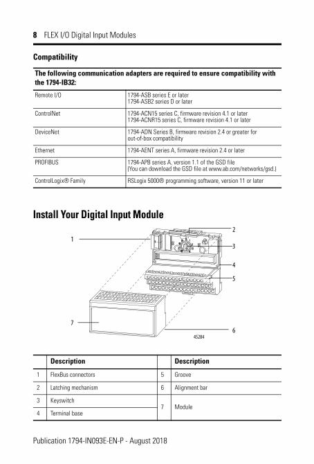
Description Description
1 FlexBus connectors 5 Groove
2 Latching mechanism 6 Alignment bar
3 Keyswitch 7
Module
4 Terminal base
6
1
7
5
4
3
2
45284
Publication 1794-IN093E-EN-P - August 2018
FLEX I/O Digital Input Modules 9
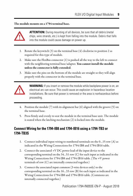
The module mounts on a 1794 terminal base.
1. Rotate the keyswitch (3) on the terminal base (4) clockwise to position 2 as required for this type of module.
2. Make sure the FlexBus connector (1) is pushed all the way to the left to connect with the neighboring terminal base/adapter. You cannot install the module unless the connector is fully extended.
3. Make sure the pins on the bottom of the module are straight so they will align properly with the connector in the terminal base.
4. Position the module (7) with its alignment bar (6) aligned with the groove (5) on the terminal base.
5. Press firmly and evenly to seat the module in the terminal base unit. The module is seated when the latching mechanism (2) is locked into the module.
Connect Wiring for the 1794-IB8 and 1794-IB16 using a 1794-TB3 or 1794-TB3S
1. Connect individual input wiring to numbered terminals on the 0…15 row (A) as indicated in the Wiring Connections for 1794-IB8 and 1794-IB16 table.
2. Connect the associated +V DC power lead of the input device to the corresponding terminal on the 34…51 row (C) for each input as indicated in the Wiring Connections for 1794-IB8 and 1794-IB16 table. (The +V power terminals of row (C) are internally connected together.)
3. Connect the associated input common (3-wire devices only) to the corresponding terminal on the 16…33 row (B) for each input as indicated in the Wiring Connections for 1794-IB8 and 1794-IB16 table. (Commons are internally connected together.)
ATTENTION: During mounting of all devices, be sure that all debris (metal chips, wire strands, etc.) is kept from falling into the module. Debris that falls into the module could cause damage on power up.
WARNING: If you insert or remove the module while backplane power is on, an electrical arc can occur. This could cause an explosion in hazardous location installations. Be sure that power is removed or the area is nonhazardous before proceeding.
Publication 1794-IN093E-EN-P - August 2018
10 FLEX I/O Digital Input Modules
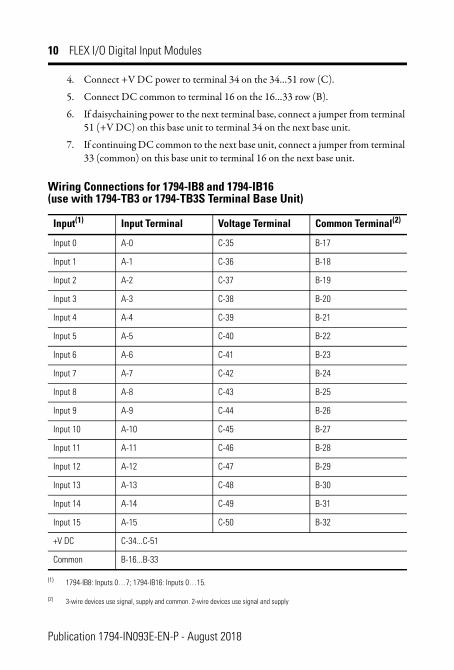
4. Connect +V DC power to terminal 34 on the 34…51 row (C).
5. Connect DC common to terminal 16 on the 16…33 row (B).
6. If daisychaining power to the next terminal base, connect a jumper from terminal 51 (+V DC) on this base unit to terminal 34 on the next base unit.
7. If continuing DC common to the next base unit, connect a jumper from terminal 33 (common) on this base unit to terminal 16 on the next base unit.
Wiring Connections for 1794-IB8 and 1794-IB16(use with 1794-TB3 or 1794-TB3S Terminal Base Unit)
Input(1)
(1) 1794-IB8: Inputs 0…7; 1794-IB16: Inputs 0…15.
Input Terminal Voltage Terminal Common Terminal(2)
(2) 3-wire devices use signal, supply and common. 2-wire devices use signal and supply
Input 0 A-0 C-35 B-17
Input 1 A-1 C-36 B-18
Input 2 A-2 C-37 B-19
Input 3 A-3 C-38 B-20
Input 4 A-4 C-39 B-21
Input 5 A-5 C-40 B-22
Input 6 A-6 C-41 B-23
Input 7 A-7 C-42 B-24
Input 8 A-8 C-43 B-25
Input 9 A-9 C-44 B-26
Input 10 A-10 C-45 B-27
Input 11 A-11 C-46 B-28
Input 12 A-12 C-47 B-29
Input 13 A-13 C-48 B-30
Input 14 A-14 C-49 B-31
Input 15 A-15 C-50 B-32
+V DC C-34...C-51
Common B-16...B-33
Publication 1794-IN093E-EN-P - August 2018
FLEX I/O Digital Input Modules 11
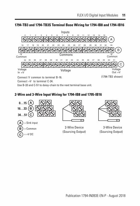
1794-TB3 and 1794-TB3S Terminal Base Wiring for 1794-IB8 and 1794-IB16
2-Wire and 3-Wire Input Wiring for 1794-IB8 and 1795-IB16
(1794-TB3 shown)Connect V common to terminal B-16.Connect +V to terminal C-34.
VoltageIn +V
VoltageOut +V
Voltage
A
B
C
Common-V
Common
Use B-33 and C-51 to daisy-chain to the next terminal base unit.
= Sink input
= Common
= +V DC
0…15
16…33
34…51
A
B
C
A
B
C
2-Wire Device(Sourcing Output)
3-Wire Device(Sourcing Output)
Publication 1794-IN093E-EN-P - August 2018
12 FLEX I/O Digital Input Modules
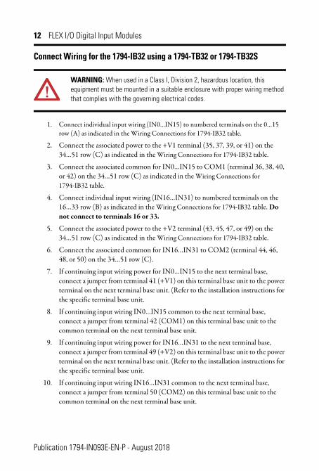
Connect Wiring for the 1794-IB32 using a 1794-TB32 or 1794-TB32S
1. Connect individual input wiring (IN0…IN15) to numbered terminals on the 0…15 row (A) as indicated in the Wiring Connections for 1794-IB32 table.
2. Connect the associated power to the +V1 terminal (35, 37, 39, or 41) on the 34…51 row (C) as indicated in the Wiring Connections for 1794-IB32 table.
3. Connect the associated common for IN0…IN15 to COM1 (terminal 36, 38, 40, or 42) on the 34…51 row (C) as indicated in the Wiring Connections for 1794-IB32 table.
4. Connect individual input wiring (IN16…IN31) to numbered terminals on the 16…33 row (B) as indicated in the Wiring Connections for 1794-IB32 table. Do not connect to terminals 16 or 33.
5. Connect the associated power to the +V2 terminal (43, 45, 47, or 49) on the 34…51 row (C) as indicated in the Wiring Connections for 1794-IB32 table.
6. Connect the associated common for IN16…IN31 to COM2 (terminal 44, 46, 48, or 50) on the 34…51 row (C).
7. If continuing input wiring power for IN0…IN15 to the next terminal base, connect a jumper from terminal 41 (+V1) on this terminal base unit to the power terminal on the next terminal base unit. (Refer to the installation instructions for the specific terminal base unit.
8. If continuing input wiring IN0…IN15 common to the next terminal base, connect a jumper from terminal 42 (COM1) on this terminal base unit to the common terminal on the next terminal base unit.
9. If continuing input wiring power for IN16…IN31 to the next terminal base, connect a jumper from terminal 49 (+V2) on this terminal base unit to the power terminal on the next terminal base unit. (Refer to the installation instructions for the specific terminal base unit.
10. If continuing input wiring IN16…IN31 common to the next terminal base, connect a jumper from terminal 50 (COM2) on this terminal base unit to the common terminal on the next terminal base unit.
WARNING: When used in a Class I, Division 2, hazardous location, this equipment must be mounted in a suitable enclosure with proper wiring method that complies with the governing electrical codes.
Publication 1794-IN093E-EN-P - August 2018
FLEX I/O Digital Input Modules 13
Wiring Connections for 1794-IB32(use with 1794-TB32 or 1794-TB32S Terminal Base Unit)
Input(1)
(1) 3-wire devices use signal, return and supply. 2-wire devices use signal and supply
Signal Input Signal
IN 0 A-0 IN 16 B-17
IN 1 A-1 IN 17 B-18
IN 2 A-2 IN 18 B-19
IN 3 A-3 IN 19 B-20
IN 4 A-4 IN 20 B-21
IN 5 A-5 IN 21 B-22
IN 6 A-6 IN 22 B-23
IN 7 A-7 IN 23 B-24
IN 8 A-8 IN 24 B-25
IN 9 A-9 IN 25 B-26
IN 10 A-10 IN 26 B-27
IN 11 A-11 IN 27 B-28
IN 12 A-12 IN 28 B-29
IN 13 A-13 IN 29 B-30
IN 14 A-14 IN 30 B-31
IN 15 A-15 IN 31 B-32
+V1 DC power (inputs IN0…IN15)
Power terminals 35, 37, 39, and 41 for IN0…IN15. +V1 connected to terminals 35, 37, 39, and 41.
COM1 DC Return (inputs IN0…IN15)
Common terminals 36, 38, 40, and 42 for IN0…IN15. V1 Return connected to terminals 36, 38, 40, and 42.
+V2 DC power (inputs IN16…IN31)
Power terminals 43, 45, 47, and 49 for IN16…IN31. +V2 connected to terminals 43, 45, 47, and 49.
COM2 DC Return (inputs IN16…IN31)
Common terminals 44, 46, 48, and 50 for IN16…IN31. V2 Return connected to terminals 44, 46, 48, and 50.
Publication 1794-IN093E-EN-P - August 2018
14 FLEX I/O Digital Input Modules
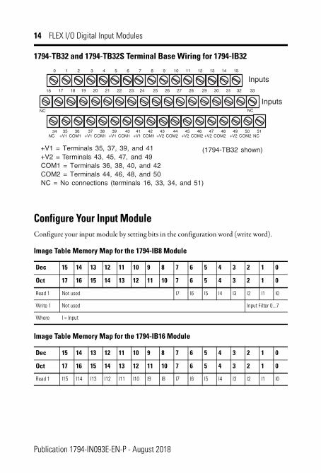
1794-TB32 and 1794-TB32S Terminal Base Wiring for 1794-IB32
Configure Your Input ModuleConfigure your input module by setting bits in the configuration word (write word).
NC = No connections (terminals 16, 33, 34, and 51)COM2 = Terminals 44, 46, 48, and 50
NC NC
(1794-TB32 shown)
Inputs
Publication 1794-IN093E-EN-P - August 2018
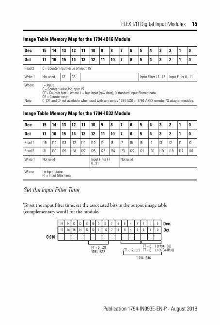
FLEX I/O Digital Input Modules 15
Set the Input Filter Time
To set the input filter time, set the associated bits in the output image table (complementary word) for the module.
Read 2 C = Counter Input value of input 15
Write 1 Not used CF CR Input Filter 12...15 Input Filter 0...11
Where
Note:
I = Input C = Counter value for input 15 CF = Counter fast – where 1 = fast input (raw data), 0 standard input filtered data CR = Counter resetC, CR, and CF not available when used with any series 1794-ASB or 1794-ASB2 remote I/O adapter modules.
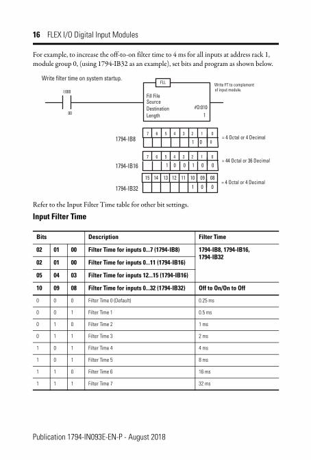
For example, to increase the off-to-on filter time to 4 ms for all inputs at address rack 1, module group 0, (using 1794-IB32 as an example), set bits and program as shown below.
Refer to the Input Filter Time table for other bit settings.
Input Filter Time
Bits Description Filter Time
02 01 00 Filter Time for inputs 0...7 (1794-IB8) 1794-IB8, 1794-IB16, 1794-IB32
02 01 00 Filter Time for inputs 0...11 (1794-IB16)
05 04 03 Filter Time for inputs 12...15 (1794-IB16)
10 09 08 Filter Time for inputs 0...32 (1794-IB32) Off to On/On to Off
0 0 0 Filter Time 0 (Default) 0.25 ms
0 0 1 Filter Time 1 0.5 ms
0 1 0 Filter Time 2 1 ms
0 1 1 Filter Time 3 2 ms
1 0 1 Filter Time 4 4 ms
1 0 1 Filter Time 5 8 ms
1 1 0 Filter Time 6 16 ms
1 1 1 Filter Time 7 32 ms
1 0 0
7 6 5 4 3
FLL
I:000
00
Fill FileSourceDestinationLength
#O:0101
Write FT to complementof input module.
Write filter time on system startup.
7 6 5 4 3 2 1 0
01 0= 4 Octal or 4 Decimal
2 1 0= 44 Octal or 36 Decimal
01 0 1 0 0
1794-IB8
1794-IB16
1 0 0= 4 Octal or 4 Decimal
1 0 01794-IB32
09 08101112131415
Publication 1794-IN093E-EN-P - August 2018
FLEX I/O Digital Input Modules 17
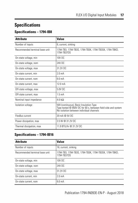
Specifications Specifications – 1794-IB8
Attribute Value
Number of inputs 8, current, sinking
Recommended terminal base unit 1794-TB3, 1794-TB3S, 1794-TB3K, 1794-TB3SK, 1794-TBKD, 1794-TB37DS
On-state voltage, min 10V DC
On-state voltage, nom 24V DC
On-state voltage, max 31.2V DC
On-state current, min 2.0 mA
On-state current, nom 8.0 mA
On-state current, max 12.0 mA
Off-state voltage, max 5.0V DC
Off-state current, max 1.5 mA
Nominal input impedance 4.6 kΩ
Isolation voltage 50V (continuous), Basic Insulation Type Type tested @ 850V DC for 60 s, between field side and system No isolation between individual channels
FlexBus current 20 mA @ 5V DC
Power dissipation, max 3.5 W @ 31.2V DC
Thermal dissipation, max 11.9 BTU/hr @ 31.2V DC
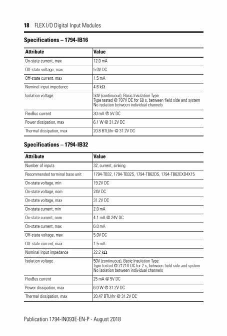
Specifications – 1794-IB16
Attribute Value
Number of inputs 16, current, sinking
Recommended terminal base unit 1794-TB3, 1794-TB3S, 1794-TB3K, 1794-TB3SK, 1794-TBKD, 1794-TB37DS
On-state voltage, min 10V DC
On-state voltage, nom 24V DC
On-state voltage, max 31.2V DC
On-state current, min 2.0 mA
On-state current, nom 8.0 mA
Publication 1794-IN093E-EN-P - August 2018
18 FLEX I/O Digital Input Modules
On-state current, max 12.0 mA
Off-state voltage, max 5.0V DC
Off-state current, max 1.5 mA
Nominal input impedance 4.6 kΩ
Isolation voltage 50V (continuous), Basic Insulation Type Type tested @ 707V DC for 60 s, between field side and system No isolation between individual channels
FlexBus current 30 mA @ 5V DC
Power dissipation, max 6.1 W @ 31.2V DC
Thermal dissipation, max 20.8 BTU/hr @ 31.2V DC
Specifications – 1794-IB32
Attribute Value
Number of inputs 32, current, sinking
Recommended terminal base unit 1794-TB32, 1794-TB32S, 1794-TB62DS, 1794-TB62EXD4X15
On-state voltage, min 19.2V DC
On-state voltage, nom 24V DC
On-state voltage, max 31.2V DC
On-state current, min 2.0 mA
On-state current, nom 4.1 mA @ 24V DC
On-state current, max 6.0 mA
Off-state voltage, max 5.0V DC
Off-state current, max 1.5 mA
Nominal input impedance 22.2 kΩ
Isolation voltage 50V (continuous), Basic Insulation Type Type tested @ 2121V DC for 2 s, between field side and system No isolation between individual channels
FlexBus current 25 mA @ 5V DC
Power dissipation, max 6.0 W @ 31.2V DC
Thermal dissipation, max 20.47 BTU/hr @ 31.2V DC
Specifications – 1794-IB16
Attribute Value
Publication 1794-IN093E-EN-P - August 2018
FLEX I/O Digital Input Modules 19
General Specifications
Attribute Value
Input filter time Refer to Input Filter Time table
Terminal base screw torque Determined by installed terminal base
Dimensions, approx. (H x W x D) 94 x 94 x 69 mm (3.7 x 3.7 x 2.7 in.)
Weight, approx. 71 g (2.50 oz.) – 1794-IB8 74 g (2.61 oz.) – 1794-IB16 79 g (2.79 oz.) – 1794-IB32
Indicators (field side indication) 8 yellow status indicators – 1794-IB8 16 yellow status indicators – 1794-IB16 32 yellow status indicators – 1794-IB32
External DC power supply voltage, nom 24V DC
External DC power voltage range 10...31.2V DC (includes 5% AC ripple) – 1794-IB8, 1794-IB16 19.2...31.2V DC (includes 5% AC ripple) – 1794-IB32
North American temperature code T3C – 1794-IB8, 1794-IB32 T4A – 1794-IB16
IEC temperature code T3 – 1794-IB8 only T4 – 1794-IB16 only
Keyswitch position 2
Enclosure type rating None (open-style)
Wire size Determined by installed terminal base
Wiring category(1) (2) 2 – on signal ports
(1) Use this Conductor Category information for planning conductor routing. Refer to Industrial Automation Wiring and Grounding Guidelines, publication 1770-4.1.
(2) Use this Conductor Category information for planning conductor routing as described in the appropriate System Level Installation Manual.
At the end of its life, this equipment should be collected separately from any unsorted municipal waste.
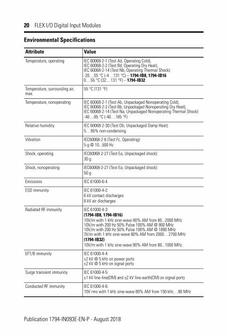
Vibration IEC60068-2-6 (Test Fc, Operating):5 g @ 10...500 Hz
Shock, operating IEC60068-2-27 (Test Ea, Unpackaged shock):30 g
Shock, nonoperating IEC60068-2-27 (Test Ea, Unpackaged shock):50 g
Emissions IEC 61000-6-4
ESD immunity IEC 61000-4-2:6 kV contact discharges8 kV air discharges
Radiated RF immunity IEC 61000-4-3:(1794-IB8, 1794-IB16)10V/m with 1 kHz sine-wave 80% AM from 80...2000 MHz 10V/m with 200 Hz 50% Pulse 100% AM @ 900 MHz 10V/m with 200 Hz 50% Pulse 100% AM @ 1890 MHz 3V/m with 1 kHz sine-wave 80% AM from 2000…2700 MHz(1794-IB32)10V/m with 1 kHz sine-wave 80% AM from 80...1000 MHz
EFT/B immunity IEC 61000-4-4:±2 kV @ 5 kHz on power ports ±2 kV @ 5 kHz on signal ports
Surge transient immunity IEC 61000-4-5:±1 kV line-line(DM) and ±2 kV line-earth(CM) on signal ports
Conducted RF immunity IEC 61000-4-6:10V rms with 1 kHz sine-wave 80% AM from 150 kHz…80 MHz
Publication 1794-IN093E-EN-P - August 2018
FLEX I/O Digital Input Modules 21
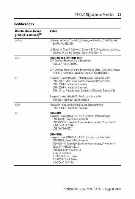
Certifications
Certifications (when product is marked)(1)
Value
c-UL-us UL Listed Industrial Control Equipment, certified for US and Canada. See UL File E322657.
UL Listed for Class I, Division 2, Group A, B, C, D Hazardous Locations, certified for US and Canada. See UL File E334470.
CSA (1794-IB8 and 1794-IB16 only)CSA Certified Process Control Equipment.
See CSA File LR54689C.
CSA Certified Process Control Equipment for Class I, Division 2, Group A, B, C, D Hazardous Locations. See CSA File LR69960C.
CE European Union 2014/30/EU EMC Directive, compliant with: EN 61326-1; Meas./Control/Lab., Industrial Requirements EN 61000-6-2; Industrial Immunity EN 61000-6-4; Industrial Emissions EN 61131-2; Programmable Controllers (Clause 8, Zone A & B)
European Union 2011/65/EU RoHS, compliant with: EN 50581; Technical Documentation
RCM Australian Radiocommunications Act, compliant with: EN 61000-6-4; Industrial Emissions
Ex (1794-IB8)European Union 2014/34/EU ATEX Directive, compliant with:
EN 60079-0; General Requirements EN 60079-15; Potentially Explosive Atmospheres, Protection “n” II 3 G Ex nA IIC T3 Gc LCIE 01ATEX6020X
(1794-IB16)European Union 2014/34/EU ATEX Directive, compliant with:
EN 60079-0; General Requirements EN 60079-15; Potentially Explosive Atmospheres, Protection “n” DEMKO 14ATEX1342501X EN 60079-0:2012+A11:2013 IECEx UL 14.0066X IEC 60079-0, 6th Edition IEC 60079-15, 4th Edition II 3 G Ex nA IIC T4 Gc
Publication 1794-IN093E-EN-P - August 2018
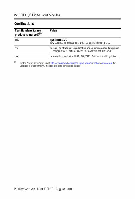
22 FLEX I/O Digital Input Modules
TÜV (1794-IB16 only)TÜV Certified for Functional Safety: up to and including SIL 2
KC Korean Registration of Broadcasting and Communications Equipment, compliant with: Article 58-2 of Radio Waves Act, Clause 3
EAC Russian Customs Union TR CU 020/2011 EMC Technical Regulation
(1) See the Product Certification link at http://www.rockwellautomation.com/global/certification/overview.page for Declarations of Conformity, Certificates, and other certification details.
The area within the curve represents the safe operating range for the module undervarious conditions of user supplied 24V DC supply voltages and ambient temperature.
= Normal mounting safe operating range, (includes ).= Other mounting positions (including inverted horizontal) safe operating range
3732
28.527.5
Normal Mounting – Horizontal
Other Mounting (including Vertical, and Inverted Horizontal Mounting)
(max.)
31.2 37 32 29.0 51 45
30.5 41 36 28.5 48
30.0 45 39 28.0 55 51
29.5 48 42 27.5 55
inVOn-StateVoltage(V DC)
Temperature
Normal Other
(max.)Temperature
Normal Other
Voltage(max.)Voltage
(max.)
Publication 1794-IN093E-EN-P - August 2018
Rockwell Automation SupportRockwell Automation provides technical information on the Web to assist you in using its products. At http://www.rockwellautomation.com/support/, you can find technical manuals, a knowledge base of FAQs, technical and application notes, sample code and links to software service packs, and a MySupport feature that you can customize to make the best use of these tools.
For an additional level of technical phone support for installation, configuration and troubleshooting, we offer TechConnect support programs. For more information, contact your local distributor or Rockwell Automation representative, or visit http://www.rockwellautomation.com/support/.
Installation AssistanceIf you experience a problem within the first 24 hours of installation, please review the information that's contained in this manual. You can also contact a special Customer Support number for initial help in getting your product up and running.
New Product Satisfaction ReturnRockwell Automation tests all of its products to ensure that they are fully operational when shipped from the manufacturing facility. However, if your product is not functioning and needs to be returned, follow these procedures.
Documentation FeedbackYour comments will help us serve your documentation needs better. If you have any suggestions on how to improve this document, complete this form, publication RA-DU002, available at http://www.rockwellautomation.com/literature/.
United States or Canada 1.440.646.3434
Outside United States or Canada
Use the Worldwide Locator at http://www.rockwellautomation.com/support/americas/phone_en.html, or contact your local Rockwell Automation representative.
United States Contact your distributor. You must provide a Customer Support case number (call the phone number above to obtain one) to your distributor to complete the return process.
Outside United States Please contact your local Rockwell Automation representative for the return procedure.
Publication 1794-IN093E-EN-P - August 2018
Allen-Bradley, Rockwell Automation, ControlLogix, FLEX I/O, RSLogix 5000, Rockwell Software, and TechConnect are trademarks of Rockwell Automation, Inc. Trademarks not belonging to Rockwell Automation are property of their respective companies.
Rockwell Automation maintains current product environmental information on its website at http://www.rockwellautomation.com/rockwellautomation/about-us/sustainability-ethics/product-environmental-compliance.page.