In the proceedings of the 39th ACM/IEEE International Symposium on Computer Architecture (ISCA), June 2012 FLEXclusion: Balancing Cache Capacity and On-chip Bandwidth via Flexible Exclusion Jaewoong Sim Jaekyu Lee Moinuddin K. Qureshi Hyesoon Kim Georgia Institute of Technology {jaewoong.sim, jaekyu.lee, moin, hyesoon.kim}@gatech.edu Abstract Exclusive last-level caches (LLCs) reduce memory ac- cesses by effectively utilizing cache capacity. However, they require excessive on-chip bandwidth to support frequent in- sertions of cache lines on eviction from upper-level caches. Non-inclusive caches, on the other hand, have the advan- tage of using the on-chip bandwidth more effectively but suffer from a higher miss rate. Traditionally, the decision to use the cache as exclusive or non-inclusive is made at de- sign time. However, the best option for a cache organization depends on application characteristics, such as working set size and the amount of traffic consumed by LLC insertions. This paper proposes FLEXclusion, a design that dynam- ically selects between exclusion and non-inclusion depend- ing on workload behavior. With FLEXclusion, the cache behaves like an exclusive cache when the application bene- fits from extra cache capacity, and it acts as a non-inclusive cache when additional cache capacity is not useful, so that it can reduce on-chip bandwidth. FLEXclusion leverages the observation that both non-inclusion and exclusion rely on similar hardware support, so our proposal can be im- plemented with negligible hardware changes. Our evalua- tions show that a FLEXclusive cache reduces the on-chip LLC insertion traffic by 72.6% compared to an exclusive design and improves performance by 5.9% compared to a non-inclusive design. 1. Introduction As modern processors step from the multi-core era to the many-core era, the design of memory hierarchies has become even more important. The capacity of the last-level cache (LLC) primarily dictates the amount of the working set that can be stored on-chip. The LLC capacity is unlikely to grow at the same rate as the number of cores on-chip. This means that the LLC capacity per core is not expected to increase for future processor generations; instead, the ra- tio of the non-LLCs to the LLC is likely to become larger as we go towards many-core on the same die. Figure 1 shows the ratio of the capacity of the on-chip non-LLCs to the to- tal capacity of the LLC for Intel processors over the past 10 years. A lower ratio means that the LLC capacity is much larger than the non-LLC capacity. For example, a ratio of 0.1 indicates that the LLC is 10 times larger than the non- LLCs. Until 2006, this ratio was steadily decreasing as pro- cessor designs focused on increasing LLC capacity in the single-core era. However, with the introduction of multi- core processors, the ratio has not scaled down further since 2006. Instead, the ratio has significantly increased in recent micro-architectures that adopt the L3 cache as the LLC. For example, AMD’s recent processor, Phenom II, has a very aggressive non-LLC-to-LLC ratio of 0.5, a design in which a 6 MB LLC is shared among six cores that each have a private 512KB L2 cache core [1]. In this case, an inclusive design for the L3 cache would end up consuming half of the LLC capacity for simply replicating the blocks that are already resident in the L2 cache. Therefore, an exclusive cache becomes an attractive design choice to increase effec- tive cache capacity for such designs. Inclusive LLCs have the advantage of simplifying the cache coherence protocol [3] by avoiding snoop traffic for inner-level caches. However, inclusion requires that the same cache block be duplicated in multiple cache levels, which reduces the effective LLC size, thus increasing the number of off-chip accesses. On the other hand, exclu- sive LLCs, which are preferred by AMD and VIA proces- sors [1,20], fully utilize the cache capacity by avoiding du- plication of cache blocks and allowing the snoop traffic to go to the inner level caches. Unfortunately, exclusive caches increase on-chip bandwidth requirements significantly due to the need to insert clean victims from the non-LLCs to the LLC [8, 24]. In fact, there is no cache configuration (inclusion, exclu- sion, or non-inclusion) that works best for all workloads. Each design has its own pros and cons, depending on the workload and the effective ratio of the non-LLCs to the LLC size. This motivates us to investigate dynamic designs that can configure the cache inclusion property on-the-fly de- pending on the workload requirements. To that end, we pro- pose a flexible inclusion scheme, called FLEXclusion, that adaptively configures the LLC inclusion property depend- ing on the cache capacity requirement and on-chip traffic consumption. With FLEXclusion, the LLC acts like an ex- 1
Transcript
In the proceedings of the 39th ACM/IEEE International Symposium on Computer Architecture (ISCA), June 2012
FLEXclusion: Balancing Cache Capacity and On-chip Bandwidth
via Flexible Exclusion
Jaewoong Sim Jaekyu Lee Moinuddin K. Qureshi Hyesoon Kim
Georgia Institute of Technology{jaewoong.sim, jaekyu.lee, moin, hyesoon.kim}@gatech.edu
cesses by effectively utilizing cache capacity. However, they
require excessive on-chip bandwidth to support frequent in-
sertions of cache lines on eviction from upper-level caches.
Non-inclusive caches, on the other hand, have the advan-
tage of using the on-chip bandwidth more effectively but
suffer from a higher miss rate. Traditionally, the decision
to use the cache as exclusive or non-inclusive is made at de-
sign time. However, the best option for a cache organization
depends on application characteristics, such as working set
size and the amount of traffic consumed by LLC insertions.
This paper proposes FLEXclusion, a design that dynam-
ically selects between exclusion and non-inclusion depend-
ing on workload behavior. With FLEXclusion, the cache
behaves like an exclusive cache when the application bene-
fits from extra cache capacity, and it acts as a non-inclusive
cache when additional cache capacity is not useful, so that
it can reduce on-chip bandwidth. FLEXclusion leverages
the observation that both non-inclusion and exclusion rely
on similar hardware support, so our proposal can be im-
plemented with negligible hardware changes. Our evalua-
tions show that a FLEXclusive cache reduces the on-chip
LLC insertion traffic by 72.6% compared to an exclusive
design and improves performance by 5.9% compared to a
non-inclusive design.
1.. Introduction
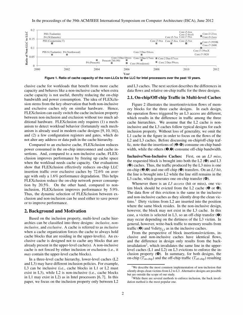
As modern processors step from the multi-core era tothe many-core era, the design of memory hierarchies hasbecome even more important. The capacity of the last-levelcache (LLC) primarily dictates the amount of the workingset that can be stored on-chip. The LLC capacity is unlikelyto grow at the same rate as the number of cores on-chip.This means that the LLC capacity per core is not expectedto increase for future processor generations; instead, the ra-tio of the non-LLCs to the LLC is likely to become larger aswe go towards many-core on the same die. Figure 1 showsthe ratio of the capacity of the on-chip non-LLCs to the to-tal capacity of the LLC for Intel processors over the past 10
years. A lower ratio means that the LLC capacity is muchlarger than the non-LLC capacity. For example, a ratio of0.1 indicates that the LLC is 10 times larger than the non-LLCs. Until 2006, this ratio was steadily decreasing as pro-cessor designs focused on increasing LLC capacity in thesingle-core era. However, with the introduction of multi-core processors, the ratio has not scaled down further since2006. Instead, the ratio has significantly increased in recentmicro-architectures that adopt the L3 cache as the LLC. Forexample, AMD’s recent processor, Phenom II, has a veryaggressive non-LLC-to-LLC ratio of 0.5, a design in whicha 6 MB LLC is shared among six cores that each have aprivate 512KB L2 cache core [1]. In this case, an inclusivedesign for the L3 cache would end up consuming half ofthe LLC capacity for simply replicating the blocks that arealready resident in the L2 cache. Therefore, an exclusivecache becomes an attractive design choice to increase effec-tive cache capacity for such designs.
Inclusive LLCs have the advantage of simplifying thecache coherence protocol [3] by avoiding snoop traffic forinner-level caches. However, inclusion requires that thesame cache block be duplicated in multiple cache levels,which reduces the effective LLC size, thus increasing thenumber of off-chip accesses. On the other hand, exclu-sive LLCs, which are preferred by AMD and VIA proces-sors [1, 20], fully utilize the cache capacity by avoiding du-plication of cache blocks and allowing the snoop traffic togo to the inner level caches. Unfortunately, exclusive cachesincrease on-chip bandwidth requirements significantly dueto the need to insert clean victims from the non-LLCs to theLLC [8, 24].
In fact, there is no cache configuration (inclusion, exclu-sion, or non-inclusion) that works best for all workloads.Each design has its own pros and cons, depending on theworkload and the effective ratio of the non-LLCs to the LLCsize. This motivates us to investigate dynamic designs thatcan configure the cache inclusion property on-the-fly de-pending on the workload requirements. To that end, we pro-pose a flexible inclusion scheme, called FLEXclusion, thatadaptively configures the LLC inclusion property depend-ing on the cache capacity requirement and on-chip trafficconsumption. With FLEXclusion, the LLC acts like an ex-
1
In the proceedings of the 39th ACM/IEEE International Symposium on Computer Architecture (ISCA), June 2012
PIII (Coopermine T)
PIII (Tualantin)
PIII-S (Tualantin)
P4 (Willamette)
P4 (Northwood)
P4 (Prescott)Prescott 2M (90)
Core (Woodcrest)
Core 2 Duo E6xxx Core 2 Duo L7xxx
Core 2 Duo E4xxx
Core 2 Duo E7xxx
Core 2 Duo P9xxx
Core i7-9xx
Core i5-7xx
Core i7-8xx Core i3-5xx
Core i5-6xxCore i7-8xxSCore i7-9xx
Core i7-2600
Core i3-21xx
Core i7-3820
Core i5-2xxx
Core i7-3930K
Core i7-39xxX
0
0.05
0.1
0.15
0.2
2000 2002 2004 2006 2008 2010 2012
Ra
tio
of
No
n-L
LC
to
LL
C
Year
Figure 1. Ratio of cache capacity of the nonLLCs to the LLC for Intel processors over the past 10 years.
clusive cache for workloads that benefit from more cachecapacity and behaves like a non-inclusive cache when extracache capacity is not useful, thereby reducing the on-chipbandwidth and power consumption. The idea of FLEXclu-sion stems from the key observation that both non-inclusiveand exclusive caches rely on similar hardware. Hence,FLEXclusion can easily switch the cache inclusion propertybetween non-inclusion and exclusion without too much ad-ditional hardware. FLEXclusion only requires (1) a mech-anism to detect workload behavior (fortunately such mech-anism is already used in modern cache designs [9, 10, 16]),and (2) a few configuration registers and gates, which donot alter any address or data path in the cache hierarchy.
Compared to an exclusive cache, FLEXclusion reducespower consumed in the on-chip interconnect and cache in-sertions. And, compared to a non-inclusive cache, FLEX-clusion improves performance by freeing up cache spacewhen the workload needs cache capacity. Our evaluationsshow that FLEXclusion effectively reduces on-chip LLCinsertion traffic over exclusive caches by 72.6% on aver-age with only a 1.6% performance degradation. This helpsFLEXclusion reduce the on-chip network power consump-tion by 20.5%. On the other hand, compared to non-inclusion, FLEXclusion improves performance by 5.9%.Thus, the dynamic selection of FLEXclusion between ex-clusion and non-inclusion can be used either to save poweror to improve performance.
2.. Background and Motivation
Based on the inclusion property, multi-level cache hier-archies can be classified into three designs: inclusive, non-inclusive, and exclusive. A cache is referred to as inclusivewhen a cache organization forces the cache to always holdcache blocks that are residing in the upper-level(s). An ex-clusive cache is designed not to cache any blocks that arealready present in the upper-level cache(s). A non-inclusivecache is not forced by either inclusion or exclusion (i.e., itmay contain the upper-level cache blocks).
In a three-level cache hierarchy, lower-level caches (L2and L3) may have different inclusion policies. For example,L3 can be inclusive (i.e., cache blocks in L1 or L2 mustexist in L3), while L2 is non-inclusive (i.e., cache blocksin L1 may exist in L2) as in Intel processors [6, 7]. In thispaper, we focus on the inclusion property only between L2
and L3 caches. The next section describes the differences indata flows and relative on-chip traffic for the three designs.
2.1.. Onchip/Offchip Traffic in Multilevel Caches
Figure 2 illustrates the insertion/eviction flows of mem-ory blocks for the three cache designs. In each design,the operation flows triggered by an L3 access are different,which results in the difference in traffic among the threecache hierarchies. We assume that the L2 cache is non-inclusive and the L3 caches follow typical designs for eachinclusion property. Without loss of generality, we omit theL1 cache in the figure in order to focus on the flows of theL2 and L3 caches. Before discussing on-chip/off-chip traf-fic, note that the insertions of (·-») consume on-chip band-width, while the others (¶,¼) consume off-chip bandwidth.
Inclusive/Non-Inclusive Caches: First, on an L3 miss,the requested block is brought into both the L2 (º) and L3(·) caches. Thus, the traffic produced by the L3 miss is oneon-chip (·,º) and one off-chip (¶) transfers. On an L3 hit,the line is brought into L2 while the line still remains in theL3 cache, which generates one on-chip transfer (»).
Whenever there is an L3 access (hit or miss), one vic-tim block should be evicted from the L2 cache (¸ or ¹).The data flow of this eviction is the same in the inclusiveand non-inclusive caches as they silently drop the clean vic-tims.1 Dirty victims from L2 are inserted into the positionwhere the same block resides. In the non-inclusive design,however, the block may not exist in the L3 cache. In thiscase, a victim is selected in L3, so an off-chip transfer (¼)may occur depending on the dirtiness of the L3 victim. Ingeneral, however, write-back traffic to memory results fromtraffic (·) and %dirtyL3 as in the inclusive caches.
From the perspective of block insertions/evictions, in-clusive and non-inclusive caches have identical flows,and the difference in design only results from the back-
invalidation2, which invalidates the same line in the upper-level caches (L1 and L2) on L3 evictions to enforce the in-clusion property (½). In summary, for both designs, theon-chip (Ton-chip) and the off-chip traffic (Toff-chip) resulting
1We describe the most common implementation of non-inclusion thatsilently drops clean victims from L2 to L3. Alternative designs are possiblebut are outside the scope of our study.
2While there are several methods to enforce inclusion, the back invali-dation method is the most popular one.
2
In the proceedings of the 39th ACM/IEEE International Symposium on Computer Architecture (ISCA), June 2012
L2
L3 (LLC)
(a) Inclusive LLC
Clean Victim Dirty Victim
L2
L3 (LLC)
(b) Non-Inclusive LLC
Clean Victim Dirty Victim
L2
L3 (LLC)
(c) Exclusive LLC
Clean Victim Dirty Victim
L3 Hit
1
3 4
2
5
3
4
8
1
2
5
3
4
1
5 6 Back-invalidation L3 Hit6
L3 Hit6 7 7 7
Memory Memory Memory
L2
L3 (LLC)
Clean Victim Dirty Victim
11
22
55
33
44
88 Back-invalidation
L3 Hit6677
Memory
L2
L3 (LLC)
Clean Victim Dirty Victim
L3 Hit
33 44
11
55 66
77
Memory
L2
L3 (LLC)
Clean Victim Dirty Victim
11
22
55
33
44
L3 Hit66
77
Memory
Figure 2. Block insertion/eviction flows for three different multilevel cache hierarchies.
Exclusive Caches: On an L3 miss, the requested blockis inserted only into the L2 cache (º), unlike in the otherdesigns. However, note that one L3 miss generates the sameamount of on/off-chip traffic as that in the inclusive/non-inclusive caches (¶,º). On an L3 hit, the hitting line isinserted into the L2 cache while invalidating the line in L3.Thus, the traffic resulting from an L3 hit is the same as thatin inclusive/non-inclusive caches.
Similar to the inclusive/non-inclusive caches, an L3 ac-cess (hit or miss) leads to an L2 eviction. However, in exclu-sive caches, the victim line is always installed into the L3cache regardless of its dirty status (¸,¹). Note that cleanvictims (¸) in inclusive/non-inclusive caches are alwaysdropped silently without the insertion into L3 caches. Thevictims (¸,¹) from L2 cause L3 evictions unless they areinserted into the position invalidated due to L3 hits. Notethat, depending on cache designs, the L2 victim resultingfrom an L3 hit may also not be installed into the invalidatedposition (i.e., the hitting line) in L3. In summary, the trafficin the exclusive cache can be represented as follows:
Traffic Comparison of Non-Inclusion and Exclusion:Using the above equations, the difference in traffic betweenthe non-inclusive and exclusive designs can be expressed as
Tdiff = Ton-chip diff + Toff-chip diff
= #missL2 − #missL2 ×%dirtyL2 + Toff-chip diff
= #missL2 ×%cleanL2 + (Toff-chip EX − Toff-chip NICL). (5)
For on-chip traffic, note that #missL2 is not affected by theL3 cache designs. Instead, it is a function of the parametersof the L2 cache and program behavior. Thus, the L2 inser-tion traffic (º,») is the same between Eq. (1) and Eq. (3),and they cancel out. As a result, the difference in trafficonly comes from the on-chip L3 insertion traffic, which is(¸,¹). We can also expect that the on-chip L3 insertiontraffic remains the same, in both designs, even if the L3 sizeis changed since it is determined by #missL2 and %dirtyL2,which are independent of the L3 configurations.
We will not elaborate the difference in off-chip trafficas we focus on on-chip traffic.3 In general, Toff-chip EX issmaller than Toff-chip NICL since the L3 miss ratio in exclusivecaches is lower than that in non-inclusive caches. However,if running workloads fit in the L3 cache or have very largememory footprints, the difference in miss ratio could be in-significant. In this case, the difference in off-chip trafficbetween non-inclusive and exclusive designs is negligible.
2.2.. Need for Dynamic Mechanism
Exclusive LLCs usually perform better than non-inclusive LLCs for the same cache size. Figure 3 shows thatthis is mainly due to the increase in effective cache capacity.
0.95
1
1.05
1.1
1.15
1:2 1:4 1:8Per
form
an
ce R
ela
tiv
e
to N
on
-In
clu
sion
Ratio of L2 to L3 Caches
Figure 3. Performance of noninclusive and exclusive LLCs
varying the LLC size for SPEC2K6 benchmarks.
With a 1:2 ratio for the L2 and L3 caches, the increasein cache size is 50% over the non-inclusive design, whichresults in a performance difference of 9.4% between thetwo designs. However, as the ratio becomes smaller (1:4and 1:8), the performance gain over non-inclusive LLCs
3The difference in off-chip transfers between non-inclusive and exclu-sive caches is much smaller than the difference in on-chip transfers.
3
In the proceedings of the 39th ACM/IEEE International Symposium on Computer Architecture (ISCA), June 2012
becomes insignificant, thereby making non-inclusive LLCsperform comparably to exclusive LLCs.
On the other hand, the LLC insertion traffic in the ex-clusive hierarchy is typically much higher than in the non-inclusive one, and the traffic remains the same even thoughthe L3 size is increased since it is determined by the L2cache size for a given application (Eq. (3)). This higheramount of traffic can only be justified when there is a no-ticeable performance difference between the exclusive andnon-inclusive LLCs. To provide a concrete example, wemeasure performance and L3 insertions per kilo instruc-tions (L3 IPKI) of a dense matrix multiplication applicationwhose working set size is 1MB (L2 cache size is 256KB).Figure 4 shows that if the L3 size is 512KB, the exclusiveL3 performs 1.45 times better than the same size of the non-inclusive L3 cache. However, if the L3 size is greater than1MB, the performance difference becomes smaller. Notethat the L3 IPKI remains the same across all configura-tions. Thus, for this workload, considering the bandwidthconsumption as well as performance, the 1MB and 2MBL3 should be non-inclusive, while the 512KB L3 should beexclusive. This implies that the best cache configuration de-pends on workload behavior, and a static policy is unable toadapt across workload changes.
Exclusive
(512KB)
Exclusive
(1MB)Exclusive
(2MB)
0
2
4
6
8
0.9 1.0 1.1 1.2 1.3 1.4 1.5
L3
IP
KI
Dif
fere
nce
IPC Normalized to Non-Inclusion
Figure 4. For dense matrix multiply, performance and L3 IPKI
difference as the LLC size is varied for an exclusive design.
3.. FLEXclusion
To avoid the disadvantages of a static cache organiza-tion, we propose FLexible EXclusion (FLEXclusion). Acache that implements FLEXclusion is called a FLEXclu-sive cache. A FLEXclusive cache operates in one of twomodes: exclusive mode or non-inclusive mode, which aredetermined at run-time using traffic monitoring and de-cision mechanisms. This section describes the proposedFLEXclusion scheme.
3.1.. Operation of FLEXclusive cache
Figure 5 shows an overview of the FLEXclusive cache.The data flow is composed of both non-inclusion and ex-clusion data paths, and two additional logic/registers con-trol the data flow based on operating mode: (1) EXCL-REG:one-bit register in the L2 cache controller to decide whetherclean victims are inserted into L3 or silently dropped, (2)NICL-GATE: logic that controls the data flow for incomingblocks from DRAM to L3.
Policy Decision Logic
(PDL)
Last-Level Cache
(LLC)
L2 Cache
L3 Line Fill Performance Metrics
L2 Victim
Signal 1 (Exclusive)
0 (Non-Inclusive)
Information Collecting
Logic (ICL)
Cache MissL3 IPKI
EXCL-REG
DRAM Memory
Off-Chip
Interconnection
Network
L3 Insertion
(Exclusive (1))
On-Chip
Interconnection
Network
NICL-GATE
L2 Line Fill
Silent Drop
(Non-Inclusive (0))
Figure 5. Hardware mechanisms and data flows in the FLEXclu
sive cache (shaded boxes indicate additional logic).
Exclusive Mode: Policy decision logic (PDL) (Sec-tion 3.2.2) sends the signal 1 (exclusion) to (1) NICL-GATE: in order not to insert incoming blocks from theDRAM to the L3 cache, (2) L3 insertion path: to invali-date the hitting lines in L3, and (3) EXCL-REG: to insertL2 clean victims to the L3 cache. The exclusive modein FLEXclusion behaves the same as in typical exclusivecaches except for the L3 insertion of L2 victims, which isperformed in a similar way to write-back updates in non-inclusive caches.4
Non-Inclusive Mode: As opposed to the exclusive de-sign, the PDL resets the EXCL-REG to prevent clean vic-tim insertions into the L3 cache. Also, all incoming blocksfrom the DRAM are inserted into both L2 and L3 caches.Although there could be multiple design choices regardingnon-inclusive caches, the non-inclusive mode in the FLEX-clusive cache follows the typical non-inclusive cache behav-ior described in Section 2. The characteristics of the operat-ing modes are summarized in Table 1.
3.2.. Operating Mode Decision
3.2.1. Collecting Cache Information The informationcollecting logic (ICL) in Figure 6 gathers information fromthe L3 cache based on the set dueling method [16] but isextended to check cache misses as well as insertion traffic.
Set 0
Set 1
Set 2
Set 3
Set 4
Set 5
Set 6
Set 7
Non-Inclusive Set
Exclusive Set
Following Set
Signal
Logic
Signal
Logic
Policy Holder
Extension (1)
Non-Extension (0)
Exclusion (1)
Non-Inclusion (0)
PDL ICL
Counters
Cache Miss
Cache Miss
Insertion
Insertion
Figure 6. Highlevel block diagram for mode selection.
In our evaluations, we set 16 dedicated non-inclusive setsand 16 dedicated exclusive sets per 1024 L3 sets (the num-ber of required sampling sets is well discussed in [16]),
4Note that this does not incur additional costs since a tag lookup needsto be performed in typical exclusive caches as well.
4
In the proceedings of the 39th ACM/IEEE International Symposium on Computer Architecture (ISCA), June 2012
Operating Mode Clean Victims (L2) Line Fill (DRAM) EXCL-REG NICL-GATE (output) Traffic (Ton-chip)
Non-inclusive mode Silent drop Both L2 and L3 Set to false (0) True (Requested data) Eq. (1)
Exclusive mode Insert Only L2 Set to true (1) False (None) Eq. (3)
Table 1. Characteristics of different operating modes in FLEXclusion.
and the other sets follow the winning policy. Each dedi-cated exclusive/non-inclusive set follows its exclusion/non-inclusion behaviors. For example, if there is a hit on one ofthe exclusive dedicated sets, the hitting line is invalidated,while if the hit is on one of the non-inclusive sets, the hit-ting line remains in the L3 cache. For the dedicated sets, theL3 insertion traffic and cache misses are monitored and thenare fed to the policy decision logic periodically. We spreadthe dedicated sets across the L3 cache sets to improve theeffectiveness of set sampling.
3.2.2. Setting Operating Mode Policy decision logic(PDL) decides which mode should be triggered for theFLEXclusive cache using the information from ICL. If theestimated performance of the exclusive mode is higher thanthat of the non-inclusive mode, PDL sends a signal to theL3 cache to run it as the exclusive mode. Otherwise, theFLEXclusive cache is configured as the non-inclusive mode.We used two metrics to determine the operating region ofFLEXclusion: cache misses (performance) and L3 inser-tions per kilo instructions (traffic). Figure 7 illustrates theoperating regions including extensions of FLEXclusion thatwill be explained in the following section.
L3 IPKI
1.0 Perfth
Insertionth
Non-Inclusive Mode
Exclusive ModeNon-Inclusive Mode
(Aggressive)
Performance Relative
to Non-Inclusion (Cache Miss)
Exclusive Mode
(Bypass)
Figure 7. Operating regions for FLEXclusive caches.
FLEXclusion does not require any special actions on atransition from one mode to another. For example, if L3is switched to non-inclusive mode, L2 clean victims aredropped even though they might not be in L3. However,this does not cause any correctness problems. On a switchto exclusive mode, the victims from L2 may already existin the L3 cache. However, FLEXclusion does not cause anyduplicate copies since the L2 victims are inserted into theposition where the same block resides in such cases.
3.3.. Extensions of the FLEXclusive Cache
3.3.1. Per-core Inclusion Policy (PER-CORE) Whenmultiple applications are running on different cores, oneapplication may undesirably determine the decision for anL3 organization. To address this problem, the FLEXclusivecache can be configured with a per-core policy. Now, it has
distinct dedicated sets for different cores to detect applica-tion characteristics. Every L2 block also needs core identi-fication information, and fortunately, it is already providedin most of the current processors to indicate cache affinity.
3.3.2. Aggressive Non-Inclusive Mode (AGG) In thenon-inclusive cache, a cache block can exist only in the L2cache, but not in the L3 cache. In the FLEXclusive cache,since the L3 cache can be switched between non-inclusivemode and exclusive mode, this situation can occur more of-ten than other typical non-inclusive caches. In this exten-sion, when a clean L2 victim is evicted, the L3 cache ischecked to see if it contains the evicted line. If not, thevictim will be installed into the L3 cache instead of beingdropped, which effectively increases the L3 hit ratio at thecost of increases in insertion traffic and address bandwidth.
3.3.3. Operating with Other Cache Techniques (BY-
PASS) FLEXclusion is orthogonal to cache replacement,insertion, and bypass algorithms; thus, they can be syn-ergistically applied together. One of the interesting com-binations could be the integration with bypass techniquessince the FLEXclusive cache requires the same amount ofbandwidth as that of exclusive caches when it runs as theexclusive mode. Thus, we can employ bypass algorithmson FLEXclusion’s exclusive mode to further reduce the on-chip bandwidth consumption. In Section 5.5, we show thatthe FLEXclusive cache seamlessly operates with one of thestate-of-the-art bypass algorithms.
3.4.. Hardware Overhead and Design Changes
FLEXclusive cache requires negligible hardware over-head and design changes, as shown in Figure 5. Comparedto the baseline caches (both exclusive and non-inclusivecaches), we need an additional four registers to recordperformance and IPKI information for each mode, onecomparator, set dueling support5, and a few configura-tion gates/registers to control the insertion/eviction flows ofmemory blocks. All the data flows required to implementthe FLEXclusive cache are already necessary for both tradi-tional exclusive and non-inclusive caches; thus, the FLEX-clusive cache simply leverages these pre-existing data paths.
3.5.. Impact on Cache Coherence
Both non-inclusive and exclusive caches do not guaran-tee the inclusion property; therefore they need to either havea coherence directory or support snooping of inner levelcaches. As exclusive and non-inclusive caches have simi-lar flow of coherence traffic, we do not need to modify thecoherence network in order to support FLEXclusion.
5Note that the overhead to support set dueling is negligible when every32nd set is selected for set sampling. We only need one 5-input NOR gate.
5
In the proceedings of the 39th ACM/IEEE International Symposium on Computer Architecture (ISCA), June 2012
4.. Experimental Methodology
Simulation Infrastructure: We use MacSim [2], an x86simulator, for our evaluations. Table 2 shows our baselineprocessor configurations. We keep the L1 and L2 cacheparameters consistent for this study while varying the inclu-sion property and the size of the L3 cache.
Interconnect Ring (cores, L3, and a memory controller), each hop takes one cycle
DRAM DDR3-1333, FR-FCFS, 9-9-9 (CL-tRCD-tRP)
Table 2. Baseline processor configuration.
Benchmarks: We use the SPEC CPU2006 benchmarksand sample 200M instructions using SimPoint [17]. Then,based on the misses per kilo instructions (MPKI) on thebaseline processor configuration, the benchmarks are cate-gorized into three different groups. Group A represents thebenchmarks whose working set sizes are greater than the L2cache but have benefits from the L3. Group B consists of thebenchmarks whose working set sizes are much greater thanthe L3. Finally, the benchmarks in Group C either are non-memory intensive or have small working set sizes. Table 3summarizes the classification of the benchmarks.
Based on the classification, we select six benchmarksfrom Group A and seven benchmarks from Group B forthe single-threaded experiments. The benchmarks in GroupC neither cause L3 insertion traffic nor experience perfor-mance differences between non-inclusive and exclusive de-signs since they fit into the L2 cache; therefore, we excludeGroup C. For the multi-programmed workload study, we se-lect benchmarks from Groups A and B and mix the bench-marks. For the experiment, if a faster thread finishes itsentire instructions, the thread continues to execute from thebeginning to keep competing for cache resources, which issimilar to the methodology used in [5,9,23]. Tables 4 and 5summarize the benchmarks used for single-threaded andmulti-programmed workloads in this study, respectively.
Energy Model: We use Orion [22] to discuss networkpower consumption in Section 5.6. We model an on-chipnetwork with four virtual channels (VCs) per physical chan-nel, where each VC has 5 FIFO buffers. The router oper-ates with 2.0GHz clock frequency at 1.2V in a 45nm tech-nology. The link width is 64b, so that a data message isdecomposed into 9 flits (1 for address and 8 for data), whilean address packet is composed of 1 flit. The link length is
MPKI MPKI
Group A L2 L3 Group B L2 L3
bzip2 4.13 0.77 mcf 65.94 59.13
gcc 4.64 1.50 omnetpp 19.05 14.15
hmmer 3.28 0.19 bwaves 23.74 23.53
h264 1.52 0.19 soplex 35.16 23.39
xalancbmk 2.08 1.56 leslie3d 32.23 29.76
calculix 2.21 1.79 wrf 25.80 22.49
sphinx3 19.61 16.71
Table 4. Singlethreaded workloads and their MPKI values.
Type Descriptions
2-MIX-S combine the same two benchmarks in Groups A and B
2-MIX-A combine all possible two benchmarks in Groups A and B
4-MIX-S combine the same four benchmarks in Groups A and B
Table 5. Benchmarks for multiprogrammed workloads.
5mm. With these parameters, dynamic and leakage powerare calculated from Orion. Table 6 summarizes the model-ing parameters in each router component for a flit.
5.. Results and Analysis
FLEXclusion aims to be either exclusive or non-inclusive to get either the performance benefit in exclu-sion or the bandwidth savings in non-inclusion at run-time.Hence, we compare performance with exclusive caches andbandwidth consumption with non-inclusive caches whendiscussing the results of FLEXclusion (Sections 5.2 to 5.4).
bzip2
gcchmmer
h264refxalancbmkcalculix
mcf
omnetpp
bwavesleslie3d soplex
wrf
sphinx3
0
10
20
30
40
50
60
0.95 1 1.05 1.1 1.15 1.2 1.25Dif
feren
ce o
f L
3 I
nse
rti
on
P
er K
ilo
Inst
ru
cti
on
s (L
3 I
PK
I)
Performance Relative to Non-Inclusion
bzip2gcc
hmmerh264ref
xalancbmk calculix
mcf
omnetpp
bwaves
leslie3d soplex
wrf sphinx3
0
10
20
30
40
50
60
0.95 1 1.05 1.1 1.15 1.2 1.25Dif
feren
ce o
f L
3 I
nse
rti
on
P
er K
ilo
Inst
ru
cti
on
s (L
3 I
PK
I)
Performance Relative to Non-Inclusion
Less Bandwidth
Consumption
Higher Performance
xalancbmkxalancbmkxalancbmkcalculix
mcf
bwavesbwavesleslie3d
wrf
sphinx3sphinx3
(a) L2:512KB, L3:1MB (1:2 ratio)
Non-Inclusion-
Favor Group
Exclusion-Favor
Group
(b) L2:512KB, L3:4MB (1:8 ratio)
bzip2bzip2gcc
h264ref
xalancbmk
mcf
bwaves
leslie3d
wrf
Non-Inclusion-
Favor Group
Exclusion-Favor
Group
Less Bandwidth
Consumption
Higher Performance
bzip2bzip2
gcchmmer
h264ref
1.15 1.2
sphinx3
Figure 8. Performance and L3 IPKI difference between exclusion
and noninclusion (512KB L2, (a) 1MB L3, (b) 4MB L3).
6
In the proceedings of the 39th ACM/IEEE International Symposium on Computer Architecture (ISCA), June 2012
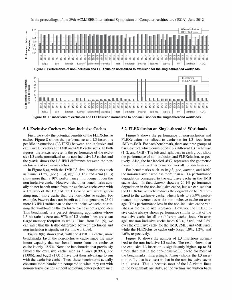
Figure 10. L3 insertions of exclusion and FLEXclusion normalized to noninclusion for the singlethreaded workloads.
5.1.. Exclusive Caches vs. Noninclusive Caches
First, we study the potential benefits of the FLEXclusivecache. Figure 8 shows the performance and L3 insertionsper kilo instructions (L3 IPKI) between non-inclusive andexclusive L3 caches for 1MB and 4MB cache sizes. In bothfigures, the x-axis represents the performance of the exclu-sive L3 cache normalized to the non-inclusive L3 cache, andthe y-axis shows the L3 IPKI difference between the non-inclusive and exclusive caches.
In Figure 8(a), with the 1MB L3 size, benchmarks suchas hmmer (1.25), gcc (1.13), bzip2 (1.13), and h264 (1.13)show more than a 10% performance improvement over thenon-inclusive cache. However, the other benchmarks actu-ally do not benefit much from the exclusive cache even witha 1:2 ratio of the L2 and the L3 cache size while gener-ating much more traffic than the non-inclusive cache. Forexample, bwaves does not benefit at all but generates 23.01more L3 IPKI traffic than on the non-inclusive cache, so run-ning the workload on the exclusive cache is not a good idea.This benchmark is a perfect streaming application whoseL3 hit ratio is zero and 97% of L2 victim lines are clean(large memory footprint as well). Thus, from Eq. (5), wecan infer that the traffic difference between exclusion andnon-inclusion is significant for this workload.
Figure 8(b) shows that, with the 4MB L3 cache, morebenchmarks favor the non-inclusive cache since the max-imum capacity that can benefit more from the exclusivecache is only 12.5%. Now, the benchmarks that previouslyfavored the exclusive cache such as hmmer (0.997), gcc(1.006), and bzip2 (1.001) have lost their advantage to runwith the exclusive cache. Thus, these benchmarks actuallyconsume more bandwidth compared to when they run withnon-inclusive caches without achieving better performance.
5.2.. FLEXclusion on Singlethreaded Workloads
Figure 9 shows the performance of non-inclusion andFLEXclusion normalized to exclusion for L3 sizes from1MB to 4MB. For each benchmark, there are three groups ofbars, each of which corresponds to a different L3 cache size(1, 2, and 4MB). The left and right bars in each group showthe performance of non-inclusion and FLEXclusion, respec-tively. Also, the bar labeled AVG. represents the geometricmean of normalized performance over all 13 benchmarks.
For benchmarks such as bzip2, gcc, hmmer, and h264,the non-inclusive cache has more than a 10% performancedegradation compared to the exclusive cache in the 1MBcache size. In fact, hmmer shows a 20.1% performancedegradation in the non-inclusive cache, but we can see thatthe FLEXclusive cache reduces the degradation to 1% com-pared to the exclusive cache, which leads to a 5.9% perfor-mance improvement over the non-inclusive cache on aver-age. This performance loss in the non-inclusive cache van-ishes as the cache size increases. However, the FLEXclu-sive cache always shows performance similar to that of theexclusive cache for all the different cache sizes. On aver-age, the non-inclusive cache loses 6.3%, 3.0%, and 2.6%over the exclusive cache for the 1MB, 2MB, and 4MB sizes,while the FLEXclusive cache only loses 1.0%, 1.2%, and1.6%, respectively.
Figure 10 shows the number of L3 insertions normal-ized to the non-inclusive L3 cache. The result shows thatthe exclusive L3 insertion is significantly higher, up to 34times, than that in the non-inclusive L3 cache for most ofthe benchmarks. Interestingly, hmmer shows the L3 inser-tion traffic that is closest to that in the non-inclusive cachein all cases. This is because most of the L2 victim linesin the benchmark are dirty, so the victims are written back
7
In the proceedings of the 39th ACM/IEEE International Symposium on Computer Architecture (ISCA), June 2012
0%
20%
40%
60%
80%
100%
bzi
p
gcc
hm
mer
h2
64
xal
ancb
mk
calc
uli
x
mcf
om
entp
p
bw
aves
lesl
ie3
d
sople
x
wrf
sphin
x3
AV
G.
Op
era
tin
g M
od
e
Exclusive Mode
Non-Inclusive Mode
0%
20%
40%
60%
80%
100%
bzi
p
gcc
hm
mer
h2
64
xal
ancb
mk
calc
uli
x
mcf
om
entp
p
bw
aves
lesl
ie3
d
sople
x
wrf
sphin
x3
AV
G.
Op
era
tin
g M
od
e
0%
20%
40%
60%
80%
100%
bzi
p
gcc
hm
mer
h2
64
xal
ancb
mk
calc
uli
x
mcf
om
entp
p
bw
aves
lesl
ie3
d
sople
x
wrf
sphin
x3
AV
G.
Op
era
tin
g M
od
e
(a) Group A+B in 1-Core (b) 2-MIX-S in 2-Cores (c) 4-MIX-S in 4-Cores
Figure 11. Percentage of the noninclusive and exclusive mode used in FLEXclusion.
to the L3 cache in both non-inclusive and exclusive caches.In contrast, in bwaves, most of the L2 victims are clean asdescribed in the previous section, which leads to 95.6%,80.2%, and 96.3% reductions in the insertion traffic com-pared to the exclusive cache for the 1MB, 2MB, and 4MBcache sizes, respectively.
Figure 10 also shows that the FLEXclusive cache effi-ciently reduces the L3 insertion traffic. For example, inbzip2, in the 1MB cache, the performance difference is high,so the FLEXclusive cache pursues the performance by con-figuring the LLC as the exclusive mode at the cost of L3insertion traffic. On the other hand, when the cache size is2MB or 4MB, the performance of non-inclusion is compara-ble to that of exclusion. Thus, FLEXclusion configures theLLC as the non-inclusive mode to reduce the traffic. On av-erage, FLEXclusion leads to 57.8% (1MB), 50.6% (2MB)and 72.6% (4MB) reductions in L3 insertion traffic.
5.3.. Adaptiveness on Effective Cache Size
FLEXclusion adaptively configures the L3 inclusionproperty, depending not only on the running workload, butalso on the effective cache size that the individual work-load experiences. For this purpose, we vary the numberof threads from one to four on quad-core CMPs with the512KB L2 and 4MB shared L3 caches. To observe the ef-fective cache sizes only, we intentionally allocate the samebenchmarks (2-MIX-S, 4-MIX-S).
As shown in Figure 11(a), when only one thread is en-joying the entire L3 cache, the non-inclusive mode is pre-ferred for the L3 inclusion on most workloads. Only for afew benchmarks, such as calculix and sphinx3, does FLEX-clusion set the L3 cache to the exclusive mode for someperiods. However, as the number of competing threads in-creases, the L3 cache is configured as the exclusive modefor more workloads in order to increase the effective cachesize for each individual thread, at the cost of on-chip traffic(Figure 11(b)). In fact, as shown in Figure 11(c), when allfour cores compete for the shared L3 cache, seven out of13 benchmarks need the L3 cache to behave as an exclusivecache for most of the running period.
5.4.. FLEXclusion on Multiprogrammed Workloads
In this section we evaluate 91 2-MIX-A multi-programmed workloads. Figure 12 shows the performance
of non-inclusion and FLEXclusion relative to exclusion andthe L3 IPKI values when 2-CPU mixed workloads are exe-cuted on the 4MB L3 cache. In each figure, the x-axis rep-resents the mixed workloads (2-MIX-A) sorted by the valuein exclusion L3 IPKI ascending order.
0.6
0.7
0.8
0.9
1
1.1
1 11 21 31 41 51 61 71 81 91
Per
form
an
ce R
ela
tiv
e
to E
xcl
usi
on
Workloads
FLEXclusionNon-Inclusion
0
20
40
60
80
1 11 21 31 41 51 61 71 81 91L3
In
sert
ion
s P
er K
ilo
Inst
ruct
ion
s (L
3 I
PK
I)
Workloads
FLEXclusionExclusionNon-Inclusion
(b) L3 Insertions Per Kilo Instructions (IPKI)
(a) Performance Normalized to Exclusion
Figure 12. Normalized performance and L3 insertions per kilo
instructions (L3 IPKI) on 2CPU workloads (2MIXA).
The result shows that FLEXclusion recovers huge per-formance drops occurring in non-inclusion. Many work-loads show more than 10% performance degradations innon-inclusion, but almost all FLEXclusion shows withina 5% range (Figure 12(a)). Furthermore, it reduces band-width consumption over exclusion when the performancedifference is insignificant, thereby overcoming the disad-vantages of static non-inclusive/exclusive LLCs. Exclusionshows high L3 IPKI in many workloads, but for the ma-jority of the workloads FLEXclusion shows significantlylow L3 IPKI and often similar to that in non-inclusion (Fig-ure 12(b)). On average, FLEXclusion reduces L3 insertiontraffic by 55.1% compared to the exclusive cache (with thecost of only 3.38% performance degradation over the exclu-sive cache) while achieving 4.78% more performance overthe non-inclusive cache.
8
In the proceedings of the 39th ACM/IEEE International Symposium on Computer Architecture (ISCA), June 2012
5.5.. Extensions on FLEXclusion
All experiments in this section use the same experimen-tal configuration (4MB L3 cache, 91 2-MIX-A) as in Sec-tion 5.4, but the workloads are sorted based on the normal-ized L3 insertions of each extension (BYPASS and AGG).
5.5.1. Bypass Algorithms with FLEXclusion (BYPASS)
To show that other cache optimization techniques can besafely applied to the FLEXclusive cache, we implementedthe static version of the bypass algorithm in [5] on top of theFLEXclusive cache. The basic idea of the bypass algorithmis to use the cache block’s usage information (from L2) andtrip counts (between L2 and L3) to find dead and live blocksfor the bypass decision, which is realized with a small num-ber of observer sets. In the FLEXclusive cache, the exist-ing dedicated exclusive sets act for the observer sets. Onlyin the exclusive mode, the bypass decision is made on thecache blocks that access the FLEXclusive cache’s followingsets, just like the original bypass mechanism is applied to anexclusive cache.
(a) Bypass Algorithm on FLEXclusion
0
0.5
1
1.5
2
0
0.5
1
1.5
1 11 21 31 41 51 61 71 81 91
L3
In
sert
ion
s
No
rma
lize
d t
o
Ex
clu
sion
Per
form
an
ce R
ela
tiv
e
to E
xcl
usi
on
Workloads
EX+BYPASS (IPC)
EX+BYPASS (L3 Insertion)
0
0.5
1
1.5
2
0
0.5
1
1.5
1 11 21 31 41 51 61 71 81 91
L3
In
sert
ion
s
No
rma
lize
d t
o
FL
EX
Clu
sio
n
Per
form
an
ce R
ela
tiv
e
to F
LE
Xcl
usi
on
Workloads
FLEX+BYPASS (IPC)
FLEX+BYPASS (L3 Insertion)
(b) Bypass Algorithm on Exclusion
Inclusive ModeExclusive Mode
Figure 13. Applying a bypass algorithm to FLEXclusion.
Figure 13 shows the performance and L3 insertions rel-ative to FLEXclusion and exclusion when a bypass algo-rithm is applied on each. As Figure 13(a) shows, almost50 workloads enter the exclusive mode in the FLEXclu-sive cache, so the bypass algorithm is applied. The resultsshow that the bypass algorithm reduces bandwidth signif-icantly, but it also sacrifices performance in the FLEXclu-sive cache. This is the same for applying the bypass algo-rithm to the baseline exclusive cache (Figure 13(b)). Asexpected, when the bypass improves performance in thebaseline, it also improves performance in the FLEXclusivecache. For example, for workload 16 and 28, employingbypass increases performance by 12.0% and 26.2% in theFLEXclusive cache and by 5.7% and 23.5% in the exclusivecache, respectively. Hence, we can conclude that the nega-tive or the benefit of bypass algorithms can be applied to the
0%
25%
50%
75%
100%
C0 C1 C0 C1 C0 C1 C0 C1 '
FLEX FLEX
+PER-CORE
FLEX FLEX
+PER-CORE
bzip2+bwaves h264ref+mcf
Op
era
tin
g M
od
e
Exclusive Mode
Non-Inclusive Mode
0
0.5
1
1.5
FLEX+PER-CORE
(Performance)
FLEX+PER-CORE
(L3 Insertion)
No
rma
lize
d t
o
FL
EX
clu
sio
n
(b)
(a)
Figure 14. (a) Operating mode distribution for bzip2+bwaves
and h264ref+mcf. C0 and C1 denote core0 and core1. (b)
Average performance and L3 insertions with +/ standard devi
ation of FLEX+PERCORE (normalized to FLEXclusion).
0
2
4
6
8
0.920.940.960.98
11.021.04
1 11 21 31 41 51 61 71 81 91
L3
In
sert
ino
s
No
rma
lize
d t
o
FL
EX
Clu
sio
n
Per
form
an
ce
Rel
ati
ve
to
FL
EX
clu
sio
n
Workloads
FLEX+AGG (IPC)FLEX+AGG (L3 Insertion)
0
0.5
1
1.5
Exclusion FLEX FLEX+AGG
L3
In
sert
ion
s
No
rma
lize
d t
o
Ex
clu
sion
(a)
(b)
Figure 15. FLEXclusion with the aggressive mode.
FLEXclusive cache. Unfortunately, unlike FLEXclusion, asimple bypass algorithm saves bandwidth consumption atthe cost of non-negligible performance loss. More complexbypass algorithms can overcome these issues, but again, thecomplex bypass algorithms can be also applied on top ofthe FLEXclusive cache. On average, FLEXclusion with thebypass algorithm reduces the L3 insertion traffic by 48.9%over FLEXclusion.
5.5.2. Per-Core Inclusion Policy (PER-CORE) To pro-vide insight into the per-core policy, we show the operat-ing mode distribution for two workload mixtures in Fig-ure 14(a). As shown in Figure 11, bzip2 and h264ref favorthe exclusive mode when multiple workloads are competingfor the shared L3 cache, while bwaves and mcf mostly fa-vor the non-inclusive mode. In the leftmost two bars (FLEXin bzip2+bwaves), we can see that L3 is set to the non-inclusive mode when bzip2 and bwaves are running on core-0 and core-1, respectively. However, the per-core policy(FLEX+PER-CORE) allows each core to have a different
9
In the proceedings of the 39th ACM/IEEE International Symposium on Computer Architecture (ISCA), June 2012
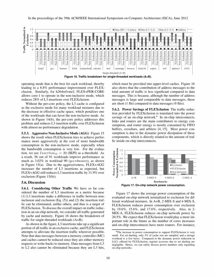
nData (MC<->Caches) Data (L3->L2) Data (L2->L3) Address
Figure 16. Traffic breakdown for singlethreaded workloads (A+B).
operating mode that is the best for each workload, therebyleading to a 8.8% performance improvement over FLEX-clusion. Similarly, for h264ref+mcf, FLEX+PER-COREallows core-1 to operate in the non-inclusive mode, whichreduces 28% of L3 insertions over FLEXclusion.
Without the per-core policy, the L3 cache is configuredas the exclusive mode for many workload mixtures due tothe decrease in effective cache space, which penalizes oneof the workloads that can favor the non-inclusive mode. Asshown in Figure 14(b), the per-core policy addresses thisproblem and reduces L3 insertion traffic over FLEXclusionwith almost no performance degradation.
5.5.3. Aggressive Non-InclusiveMode (AGG) Figure 15shows the result when FLEXclusion tries to achieve perfor-mance more aggressively at the cost of more bandwidthconsumption in the non-inclusive mode, especially whenthe bandwidth consumption is very low. For the evalua-tion, we use Insertionth = 20 (IKPI) as a threshold. Asa result, 56 out of 91 workloads improve performance asmuch as 3.02% in workload 90 (gcc+bwaves), as shownin Figure 15(a). Due to the aggressiveness, FLEX+AGGincreases the number of L3 insertions as expected, butFLEX+AGG still reduces L3 insertion traffic by 31.9% overexclusion (Figure 15(b)).
5.6.. Discussion
5.6.1. Considering Other Traffic We have so far con-sidered the number of L3 insertions as a metric because(1) L3 insertions make a difference in traffic between non-inclusion and exclusion (Eq. (5)) and (2) the insertion traf-fic can be eliminated, unlike others, and thus is a target ofFLEXclusion. To discuss the overall impact on traffic reduc-tion in an on-chip network, we consider all traffic generatedby cache and memory. Figure 16 shows the breakdown oftraffic for single-threaded workloads (A+B).
As shown in the figure, L3 insertions take up a significantportion of all traffic in an exclusive cache, and FLEXclusionattempts to alleviate the insertion traffic wherever possible.Note that data messages between a memory controller (MC)and caches cannot be reduced since they are either memoryrequests or write-backs to memory. Data messages from L3to L2 also cannot be eliminated because they are L3 hits,
which must be provided into upper-level caches. Figure 16also shows that the contribution of address messages to thetotal amount of traffic is less significant compared to datamessages. This is because, although the number of addressmessages is large and comparable to data messages, theseare short (1 flit) compared to data messages (9 flits).
5.6.2. Power Savings of FLEXclusion The traffic reduc-tion provided by FLEXclusion is translated into the powersavings of an on-chip network.6 In on-chip interconnects,links and routers are the main contributors to energy con-sumption, and router energy is mostly consumed by FIFObuffers, crossbars, and arbiters [4, 15]. Most power con-sumption is due to the dynamic power dissipation of thesecomponents, which is directly related to the amount of traf-fic inside on-chip interconnects.
0
0.2
0.4
0.6
0.8
1
1.2
A+B 2-MIX-S 4-MIX-S 2-MIX-A
Po
wer
Co
nsu
mp
tio
n
No
rma
lize
d t
o E
xcl
usi
on
Benchmarks
Exclusion
FLEXclusion
Non-Inclusion
Figure 17. Onchip network power consumption.
Figure 17 shows the average power consumption of theevaluated on-chip network normalized to exclusion for dif-ferent workload mixtures. In A+B, 2-MIX-S and 4-MIX-S,FLEXclusion reduces power consumption over exclusionby 19.6%, 15.6%, and 17.6%, respectively. Also, in 2-MIX-A, FLEXclusion reduces on-chip network power by20.5%. We expect that FLEXclusion would play a more im-portant role in the future as the number of cores increasesand on-chip interconnects have more routers. For instance,
6The increase in power consumption to support FLEXclusion is verysmall. For set dueling, only 3% of cache sets are sampled, and a storageoverhead is a few bytes. Compared to the dynamic power reduction inLLCs offered by FLEXclusion, register accesses due to set dueling arenegligible. Hence, we can safely discuss power numbers only regardingon-chip networks.
10
In the proceedings of the 39th ACM/IEEE International Symposium on Computer Architecture (ISCA), June 2012
the Raw multiprocessor [18] has a 4×4 mesh on-chip net-work, which results in consuming 7.1W (about 36% of thetotal chip power) [21]. However, the evaluation of FLEX-clusion with various on-chip networks, such as with varyingthe number of nodes and different topologies, is beyond thescope of this paper.
5.6.3. Impact of FLEXclusion on Off-chip Traffic
FLEXclusion increases off-chip traffic negligibly comparedto exclusion since it reverts from non-inclusion to exclu-sion for the workloads where the difference in off-chip ac-cesses between the two would increase significantly. Also,as shown in Figure 16 (Data (MC<->Caches) can representthe amount of off-chip traffic), the difference in off-chiptraffic between FLEXclusion and exclusion is much smallerthan the difference in on-chip traffic. For the reason, theslight increase in power expended due to extra off-chip ac-cesses is very small compared to the on-chip power savings.
5.6.4. FLEXclusion on Multi-threaded Workloads
With multi-threaded applications, FLEXclusion is expectedto perform well. When workloads do not have muchshared data, we expect that FLEXclusion has an impacton performance and traffic reduction similar to multi-programmed workloads since they resemble each otherto some extent. For workloads where data is frequentlyshared among threads, the benefit of power reductionby FLEXclusion can be a bit decreased due to cachecoherence messages. However, the energy consumption ofcoherence messages is reported to be around 18% of thetotal on-chip network [14], so FLEXclusion still can reducethe rest of the on-chip network power significantly. Inaddition, there are techniques to implement power-efficientcache coherence protocols for on-chip networks suchas [4], and FLEXclusion is orthogonal to these techniques.Hence, FLEXclusion does not lose its importance withmulti-threaded workloads.
5.6.5. Sensitivity of FLEXclusion Figure 18 shows therelationship of performance loss and L3 insertion reductionamong different performance thresholds. The results are theaverage of 91 workloads. As the results show, we can flex-ibly balance performance and bandwidth requirements bycontrolling the threshold. In this paper, we used T=5 for allexperiments. However, when on-chip bandwidth require-ments are less strict, we can use smaller threshold values toalleviate the performance loss.
6.. Related Work
6.1.. Cache Inclusion Property
Baer and Wang studied the concept of multi-level in-clusive cache hierarchies to simplify cache coherence pro-tocols [3]. Zahran et al. discussed several non-inclusioncache design strategies along with the benefits of non-inclusive caches [24]. The performance benefit of exclu-sive caches over inclusive caches has been studied by sev-eral researchers, including Zheng et al. [12, 25]. All theseworks provide the benefits and disadvantages of exclusive,
0%
10%
20%
30%
40%
50%
60%
0.0%
0.5%
1.0%
1.5%
2.0%
2.5%
3.0%
3.5%
4.0%
T=1 T=2 T=3 T=4 T=5
Red
ucti
on
in
L3
In
serti
on
s
ov
er E
xclu
sio
n
Perfo
rm
an
ce L
oss o
ver
Ex
clu
sio
n
Threshold
Reduction in L3 Insertions
Performance Loss
Figure 18. Performance loss and L3 insertion reduction of dif
ferent thresholds (T=1 is a 1% difference in cache miss ratios
between exclusive and noninclusive sets).
inclusive, and non-inclusive caches, but they assume thatthe cache inclusion policy is statically determined at designtime. However, in our FLEXclusion, we break this assump-tion and dynamically configure caches between exclusionand non-inclusion at run-time.
The most relevant work to FLEXclusion is the recentlyproposed temporal locality-aware (TLA) cache manage-ment policy by Jaleel et al. [8]. The goal of the TLA mech-anism begins from the opposite direction of FLEXclusion.FLEXclusion aims to achieve the best of both exclusivecache and non-inclusive cache, while TLA targets the bestof both non-inclusive and inclusive caches. TLA tries toachieve performance that is similar to non-inclusive cachewithout breaking the inclusion property. However, TLA stillcannot achieve performance similar to exclusive caches. Onthe contrary, the FLEXclusive cache achieves almost thesame performance as that of an exclusive cache while sav-ing on-chip bandwidth consumption significantly by operat-ing as non-inclusive mode when it is more efficient.
6.2.. Bypassing LLC Insertions
Including the recent work of Gaur et al. [5], several by-pass algorithms with dead block predictions have been pro-posed [11,13,19]. Although bypass mechanisms and FLEX-clusion share similar actions (i.e., both schemes do not in-sert some blocks into the LLC), the cause and performanceimpact are actually very different. Bypass algorithms donot insert a block when the block is predicted to be dead.On the contrary, FLEXclusion does not insert a block to theLLC because the block is already in the LLC (non-inclusivemode).7 Hence, in bypass mechanisms, bypassed blockscould result in a performance loss if the prediction is wrong(i.e., the block is live). However, bypassed blocks in FLEX-clusion do not cause a performance degradation because theblocks are still in the LLC. Furthermore, FLEXclusion canalways employ bypass mechanisms on the exclusive mode,as shown in Section 5.5.1.
7Since the non-inclusive cache does not strictly enforce inclusion, theblock might not exist in the LLC, but this happens less frequently.
11
In the proceedings of the 39th ACM/IEEE International Symposium on Computer Architecture (ISCA), June 2012
7.. Conclusions
While exclusive last-level caches (LLCs) are effectiveat reducing off-chip memory accesses by fully utilizing on-chip cache capacity, exclusive caches require higher on-chipbandwidth compared to inclusive and non-inclusive cachesdue to a higher rate of LLC insertion traffic. A non-inclusivecache, on the other hand, does not require clean victimsfrom the upper level caches to be inserted in the LLC, thusreducing the demand on an on-chip network. Unfortunately,the data replication in non-inclusive caches causes them tohave lower effective cache capacity, thereby reducing per-formance when the workload needs more cache capacity.
This paper investigated a dynamic mechanism calledFLEXclusion that can change the cache organization be-tween exclusion and non-inclusion depending on the work-load requirement. Our evaluation shows that the FLEXclu-sive cache reduces the LLC insertion traffic compared tothe static exclusive LLC design, thereby saving power. TheFLEXclusive cache also improves performance comparedto the static non-inclusive LLC cache. We also show thatthe FLEXclusive cache can employ other cache optimiza-tion techniques such as bypassing mechanisms to achievefurther benefits.
In this paper, we restricted FLEXclusion to choose be-tween non-inclusion and exclusion, as these two designshave similar coherence framework. An alternative FLEX-clusion design can also select between inclusion and othermodes; however, it would need to ensure that the inclusionrequirements are met before the cache mode is set to in-clusion (for example by flushing the upper level caches).Thus, a generalized form of FLEXclusion can be designedto adapt between inclusion, non-inclusion, and exclusion de-pending on the workload requirements. Exploring such ageneralized design is part of our future work.
Acknowledgments
Thanks to Viji Srinivasan for discussions during the earlyphase of this work. Many thanks to Si Li, other CASLmembers, Nagesh B. Lakshminarayana, HPArch membersand the anonymous reviewers for their suggestions and feed-back. We gratefully acknowledge the support of the NSFCAREER award 1139083; Sandia National Laboratories;Intel Corporation; Advanced Micro Devices. Any opinions,findings and conclusions or recommendations expressed inthis material are those of the authors and do not necessarilyreflect those of NSF, SNL, Intel, or AMD.