20
Sealing solution for your static and semi-dynamic applications FLEXIBLE GRAPHITE RINGS AND SEALS ORIGRAF ® EXPANDED GRAPHITE SEALS CEFIGRAF ® CUT GASKETS FARGRAF ® PACKING
| Date post: | 29-Oct-2018 |
| Category: |
Documents |
| Upload: | truongtuyen |
| View: | 239 times |
| Download: | 0 times |
Sealing solution for your static and semi-dynamic applications
FLEXIBLE GRAPHITE RINGS AND SEALSORIGRAF® EXPANDED GRAPHITE SEALSCEFIGRAF® CUT GASKETSFARGRAF® PACKING
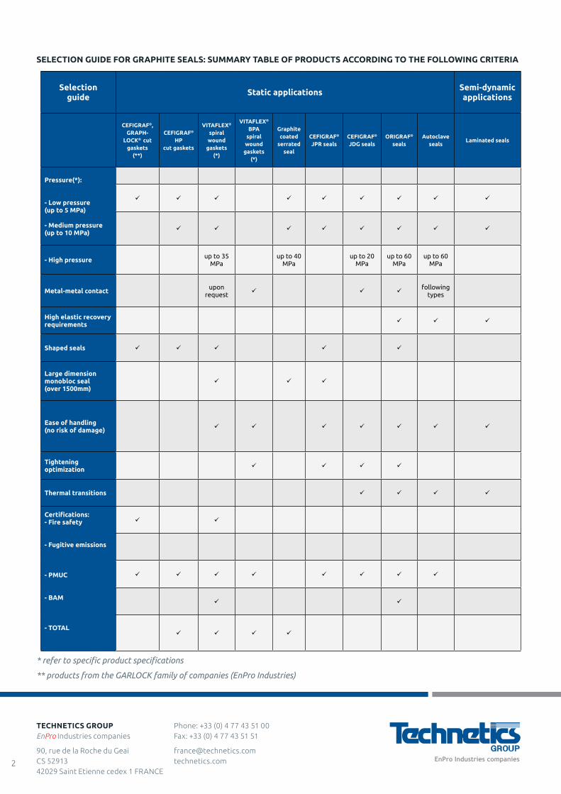
SELECTION GUIDE FOR GRAPHITE SEALS: SUMMARY TABLE OF PRODUCTS ACCORDING TO THE FOLLOWING CRITERIA
Selection guide Static applications Semi-dynamic
applications
CEFIGRAF®, GRAPH-
LOCK® cut gaskets
(**)
CEFIGRAF® HP
cut gaskets
VITAFLEX®
spiral wound
gaskets(*)
VITAFLEX® BPA
spiral wound
gaskets (*)
Graphite coated
serratedseal
CEFIGRAF® JPR seals
CEFIGRAF® JDG seals
ORIGRAF®
sealsAutoclave
sealsLaminated seals
Pressure(*):
- Low pressure (up to 5 MPa)
- Medium pressure (up to 10 MPa)
- High pressure up to 35 MPa
up to 40 MPa
up to 20 MPa
up to 60 MPa
up to 60 MPa
Metal-metal contact upon request
following types
High elastic recovery requirements
Shaped seals
Large dimension monobloc seal (over 1500mm)
Ease of handling (no risk of damage)
Tightening optimization
Thermal transitions
Certifications:- Fire safety
- Fugitive emissions
- PMUC
- BAM
- TOTAL
* refer to specific product specifications
** products from the GARLOCK family of companies (EnPro Industries)
Phone: +33 (0) 4 77 43 51 00 Fax: +33 (0) 4 77 43 51 51
[email protected] technetics.com
TECHNETICS GROUPEnPro Industries companies
90, rue de la Roche du Geai CS 52913 42029 Saint Etienne cedex 1 FRANCE
2
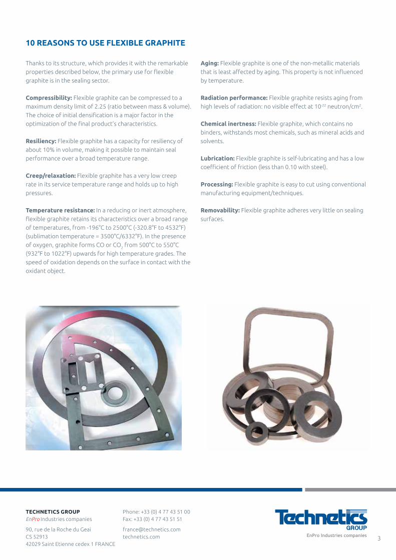
Thanks to its structure, which provides it with the remarkable
properties described below, the primary use for flexible
graphite is in the sealing sector.
Compressibility: Flexible graphite can be compressed to a
maximum density limit of 2.25 (ratio between mass & volume).
The choice of initial densification is a major factor in the
optimization of the final product’s characteristics.
Resiliency: Flexible graphite has a capacity for resiliency of
about 10% in volume, making it possible to maintain seal
performance over a broad temperature range.
Creep/relaxation: Flexible graphite has a very low creep
rate in its service temperature range and holds up to high
pressures.
Temperature resistance: In a reducing or inert atmosphere,
flexible graphite retains its characteristics over a broad range
of temperatures, from -196°C to 2500°C (-320.8°F to 4532°F)
(sublimation temperature = 3500°C/6332°F). In the presence
of oxygen, graphite forms CO or CO2 from 500°C to 550°C
(932°F to 1022°F) upwards for high temperature grades. The
speed of oxidation depends on the surface in contact with the
oxidant object.
Aging: Flexible graphite is one of the non-metallic materials
that is least affected by aging. This property is not influenced
by temperature.
Radiation performance: Flexible graphite resists aging from
high levels of radiation: no visible effect at 10-22 neutron/cm2.
Chemical inertness: Flexible graphite, which contains no
binders, withstands most chemicals, such as mineral acids and
solvents.
Lubrication: Flexible graphite is self-lubricating and has a low
coefficient of friction (less than 0.10 with steel).
Processing: Flexible graphite is easy to cut using conventional
manufacturing equipment/techniques.
Removability: Flexible graphite adheres very little on sealing
surfaces.
10 REASONS TO USE FLEXIBLE GRAPHITE
Phone: +33 (0) 4 77 43 51 00 Fax: +33 (0) 4 77 43 51 51
[email protected] technetics.com
TECHNETICS GROUPEnPro Industries companies
90, rue de la Roche du Geai CS 52913 42029 Saint Etienne cedex 1 FRANCE
3
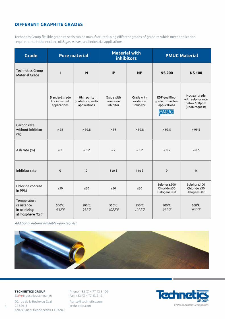
DIFFERENT GRAPHITE GRADES
Technetics Group flexible graphite seals can be manufactured using different grades of graphite which meet application
requirements in the nuclear, oil & gas, valves, and industrial applications.
Grade Pure material Material with inhibitors PMUC Material
Technetics Group Material Grade
I N IP NP NS 200 NS 100
Standard grade for industrial applications
High purity grade for specific
applications
Grade with corrosion inhibitor
Grade with oxidation inhibitor
EDF qualified-grade for nuclear
applications
Nuclear grade with sulphur rate
below 100ppm (upon request)
Carbon rate without inhibitor (%)
> 98 > 99.8 > 98 > 99.8 > 99.5 > 99.5
Ash rate (%) < 2 < 0.2 < 2 < 0.2 < 0.5 < 0.5
Inhibitor rate 0 0 1 to 3 1 to 3 0 0
Chloride content in PPM
≤50 ≤30 ≤50 ≤30Sulphur ≤200Chloride ≤30Halogens ≤80
Sulphur ≤100Chloride ≤30Halogens ≤80
Temperature resistance in oxidizing atmosphere °C/°F
500°C932°F
500°C932°F
550°C1022°F
550°C1022°F
500°C932°F
500°C932°F
Additional options available upon request.
Phone: +33 (0) 4 77 43 51 00 Fax: +33 (0) 4 77 43 51 51
[email protected] technetics.com
TECHNETICS GROUPEnPro Industries companies
90, rue de la Roche du Geai CS 52913 42029 Saint Etienne cedex 1 FRANCE
4
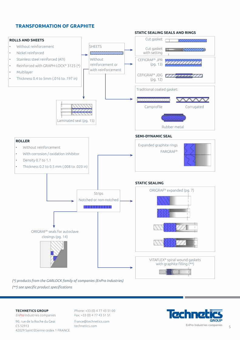
TRANSFORMATION OF GRAPHITE
STATIC SEALING
Laminated seal (pg. 15)
(*) products from the GARLOCK family of companies (EnPro Industries)
(**) see specific product specifications
ORIGRAF® seals for autoclave
closings (pg. 14)
Expanded graphite rings
FARGRAF®
STATIC SEALING SEALS AND RINGS
ROLLS AND SHEETS
• Without reinforcement
• Nickel reinforced
• Stainless steel reinforced (ATI)
• Reinforced with GRAPH-LOCK® 3125 (*)
• Multilayer
• Thickness 0.4 to 5mm (.016 to .197 in)
Without
reinforcement or
with reinforcement
SHEETS
Cut gasket
Cut gasket with setting
CEFIGRAF® JPR (pg. 13)
CEFIGRAF® JDG (pg. 12)
Camprofile
Rubber metal
Traditional coated gasket:
SEMI-DYNAMIC SEALROLLER
• Without reinforcement
• With corrosion / oxidation inhibitor
• Density 0.7 to 1.1
• Thickness 0.2 to 0.5 mm (.008 to .020 in)
ORIGRAF® expanded (pg. 7)Strips
Notched or non-notched
VITAFLEX® spiral wound gaskets with graphite filling (**)
Corrugated
Phone: +33 (0) 4 77 43 51 00 Fax: +33 (0) 4 77 43 51 51
[email protected] technetics.com
TECHNETICS GROUPEnPro Industries companies
90, rue de la Roche du Geai CS 52913 42029 Saint Etienne cedex 1 FRANCE
5

SHEETS AND CUT GASKETS
The sheets of flexible graphite are created from the different grades already described, with or without reinforcement. This rigid
reinforcement makes it easier to manipulate them.
Production possibilities / dimensional limits: Technetics Group can produce all dimensions, simple or complex shapes, intended
for sealing flanges, gland, etc. For dimensions above those of the sheets or the rollers, the seals can be made in different parts
(i.e. dove tail).
Graphite Designations - Product Specifications Characteristics
Sheet Formats Material Thickness
mm in
In Stock Upon request
mm in mm in
CEFIGRAF® NAI(without reinforcement)
Ref No. 917-10
• Non-reinforced graphite • Industrial grade • Graphite 98%
500 x 1000 19.7 x 39.4 0.4 .016
1000 x 1000 39.4 x 39.40.8 - 1 1.5 - 2
.019 - .039
.059 - .0792.5 .098
CEFIGRAF® ATN(with nickel reinforced sheet)
Ref No. 917-14
• Non-reinforced graphite • Industrial grade • Graphite 98%
500 x 1000 19.7 x 39.40.8 - 1 1.5 - 2
.019 - .039
.059 - .079
GRAPH-LOCK® 3125 SS (AA) (*)Single layer
(blue marking)Ref No. 917-44
• Single layer graphite with stainless steel insert
• Industrial grade 98%• Blue marking with anti-
adhesive treatment
1500 X 1500
59.1 x 59.1 1 - 2 .039 - .0791.5 3 4
.059
.118
.157
GRAPH-LOCK® 3125 SS (AA) (*)Multilayered(red marking)
Ref No. 917-57
• Multilayer graphite with stainless steel insert
• Industrial grade 98%• Red marking with anti-
adhesive treatment
1500 X 1500
59.1 x 59.1 2 - 3 .079 - .1181
1.5 4
.039
.059
.157
GRAPH-LOCK® 3125 TC (AA) (*)(white marking)Ref No. 917-34
• Single layer graphite with perforated stainless steel insert
• Industrial grade 98%• White marking with anti-
adhesive treatment
1500 X 1500
59.1 x 59.1 2 - 3 .079 - .118 1.5 .059
CEFIGRAF® NS 200 PMUC No. 17-0172 FT No. 918-04
• Non-reinforced graphite • High purity 99.5% grade
graphite, approved by EDF, PMUC (sulphur and halogen rate < 200ppm)
700 X 1000 27.6 x 39.4 1.5 - 3 .059 - .1181 - 23 - 4
5
.039 - .079.118- .157
.197
1000 x 1000 39.4 x 39.4 2 .079
CEFIGRAF® NS 200 HPPMUC No. 17-0189 FT No. 918-09
• Multilayer graphite with stainless steel insert
• High purity 99.5% grade graphite, approved by EDF, PMUC (sulphur and halogen rate < 200ppm)
1000 x 1000 39.4 x 39.4 2 - 3 .079 - .1181- 1.5
4.039 - .059
.157
1500 x 1500 59.1 x 59.11 - 1.5 2 - 3
4
.039 - .059
.079 - .118.157
*The above products are from the registered trademark of the GARLOCK family of companies (EnPro Industries)
Phone: +33 (0) 4 77 43 51 00 Fax: +33 (0) 4 77 43 51 51
[email protected] technetics.com
TECHNETICS GROUPEnPro Industries companies
90, rue de la Roche du Geai CS 52913 42029 Saint Etienne cedex 1 FRANCE
6

ORIGRAF® SEALS
CONCEPT AND ADVANTAGES OF ORIGRAF® SEALS
Recommendations for useThe ORIGRAF®, an expanded graphite seal, is created
from strips of CEFIGRAF® flexible graphite, densified under
pressure using special equipment. The seal is obtained through the final densification of the seal when it is tightened in contact with the mechanical stop (also known as metal-metal contact).
The metal-metal contact is obtained:
• either by assembling a graphite ring in a groove
• or by the insertion of a graphite ring between interior
and/or exterior rings which serve as tightening
limitations.
Advantages of metal-metal contact: it consists of creating
a rigid mechanical contact independent of the active part
of the graphite seal which is thus preserved against the
general mechanical assembly constraints. The resiliency of the seal only serves the sealing function. This metal to metal concept also allows the seal to be protected from over-tightening.
ORIGRAF® seal with anti-extrusion cupsORIGRAF® seals can be equipped with anti-extrusion cups. These make it possible to avoid the extrusion of graphite during the tightening phase, ensuring a targeted densification. This concept (patented system) is
recommended in the following cases:
• high pressure
• large space between metallic assembly parts
• highly corrosive fluids or fluids with high levels
of impurities, to protect the center of the seal
The cups are made using Stainless steel (316L, 304L, etc.) or
in Monel, Inconel or Silver upon request.
MAIN ADVANTAGES OF ORIGRAF® SEALS
• Excellent elastic recovery, capable of reaching 50%
of compression.
• Very good endurance in thermal transients• No marks on the sealing surfaces, making maintenance
easier when opening the flanges and replacing the seal
• Good resistance to radial movements of the flanges• Excellent ability to withstand a wide range of
temperatures: -196°C to +2500°C ( -320.8°F to +4532°F)
(in an inert environment and according to the assembly
conditions)
• Fire resistant
• Very low level of relaxation (6 to 8% max.)
AREA OF USE
Max. temp. in oxidizing environment
500°C/932°F (550°C/1022°F with corrosion inhibitor)
Max. temp. in inert environment
2500°C/4532°F in inert environment
Min. temp. -196°C/-320.8°F
Max. pressure 15 MPa
State of opening surfaces See user recommendations
Phone: +33 (0) 4 77 43 51 00 Fax: +33 (0) 4 77 43 51 51
[email protected] technetics.com
TECHNETICS GROUPEnPro Industries companies
90, rue de la Roche du Geai CS 52913 42029 Saint Etienne cedex 1 FRANCE
7
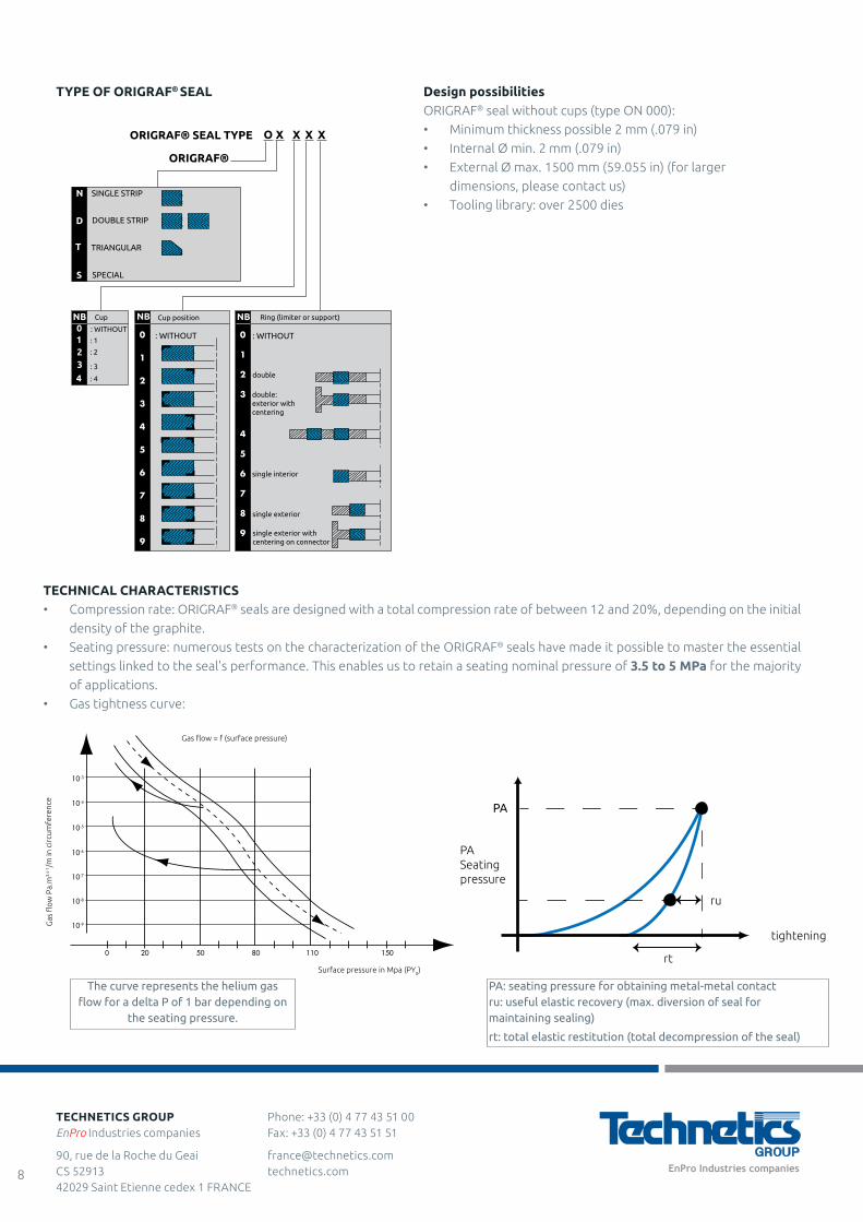
TYPE OF ORIGRAF® SEAL Design possibilitiesORIGRAF® seal without cups (type ON 000):
• Minimum thickness possible 2 mm (.079 in)
• Internal Ø min. 2 mm (.079 in)
• External Ø max. 1500 mm (59.055 in) (for larger
dimensions, please contact us)
• Tooling library: over 2500 diesSINGLE STRIP
ORIGRAF® SEAL TYPE
ORIGRAF®
DOUBLE STRIP
TRIANGULAR
SPECIAL
NB
N
D
T
S
0
1
2
3
4
: WITHOUT: WITHOUT : WITHOUT
double
double: exterior with centering
single interior
single exterior
single exterior with centering on connector
: 1
: 2
: 3
: 4
NB
XO X X X
NBCup positionCup Ring (limiter or support)
10-9
0 20 50 80 110 150
10-8
10-7
10-6
10-5
10-4
10-3
Gas flow = f (surface pressure)
Surface pressure in Mpa (PY0)
Gas fl
ow P
a.m
3.s-
1 /m in
circ
umfe
renc
e
tightening
PA Seatingpressure
PA
ru
rt
The curve represents the helium gas flow for a delta P of 1 bar depending on
the seating pressure.
PA: seating pressure for obtaining metal-metal contact ru: useful elastic recovery (max. diversion of seal for maintaining sealing)
rt: total elastic restitution (total decompression of the seal)
TECHNICAL CHARACTERISTICS• Compression rate: ORIGRAF® seals are designed with a total compression rate of between 12 and 20%, depending on the initial
density of the graphite.
• Seating pressure: numerous tests on the characterization of the ORIGRAF® seals have made it possible to master the essential
settings linked to the seal's performance. This enables us to retain a seating nominal pressure of 3.5 to 5 MPa for the majority
of applications.
• Gas tightness curve:
Phone: +33 (0) 4 77 43 51 00 Fax: +33 (0) 4 77 43 51 51
[email protected] technetics.com
TECHNETICS GROUPEnPro Industries companies
90, rue de la Roche du Geai CS 52913 42029 Saint Etienne cedex 1 FRANCE
8

TYPES OF ASSEMBLY
Standard assembly The most common types of seal Seal description
Grooved assembly ON 000
Seal composed of a single graphite ring
ON 250Seal composed of a graphite ring and 2 anti-extrusion cups
(to be placed on the opposite side to the groove base)
Assembly on flat surfaced or elevated flanges ON 002Seal composed of a graphite ring and 2 metal internal
and external rings
ON 492
Same as ON 002 with 4 anti-extrusion cups
Single insertion assembly on flange ON 242
Same as ON 002 with 2 internal anti-extrusion cups
Specific assembly methods
Double strip sealing assembly OD 492
Seal composed of 2 graphite rings and 3 metal internal, external and intermediate rings, with 4 anti-
extrusion cups and double strips
Specific forms ON 000
Shaped seals composed of a single graphite ring in a specific shape
Assembly of exhaust flange ON 002
Seal composed of one graphite ring and 2 metal internal and external rings, with the external
ring having a specific design
Electric boiler sealing ROTAGRAF®
Set of two gaskets, each composed of one triangular graphite ring with anti-extrusion cups
D0D1D2D3
BA
Phone: +33 (0) 4 77 43 51 00 Fax: +33 (0) 4 77 43 51 51
[email protected] technetics.com
TECHNETICS GROUPEnPro Industries companies
90, rue de la Roche du Geai CS 52913 42029 Saint Etienne cedex 1 FRANCE
9
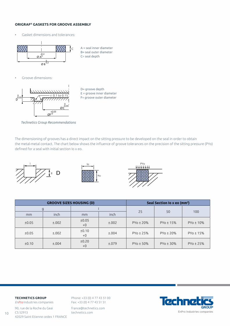
ORIGRAF® GASKETS FOR GROOVE ASSEMBLY
• Gasket dimensions and tolerances:
F
E
r: 0.1 to 0.15
F
E
r: 0.1 to 0.15
lo
eo
PYol
g D
The dimensioning of grooves has a direct impact on the sitting pressure to be developed on the seal in order to obtain
the metal-metal contact. The chart below shows the influence of groove tolerances on the precision of the sitting pressure (PYo)
defined for a seal with initial section Io x eo.
Technetics Group Recommendations
GROOVE SIZES HOUSING (D) Seal Section Io x eo (mm2)
g I25 50 100
mm inch mm inch
±0.05 ±.002±0.05
+0±.002 PYo ± 20% PYo ± 15% PYo ± 10%
±0.05 ±.002±0.10
+0±.004 PYo ± 25% PYo ± 20% PYo ± 15%
±0.10 ±.004±0.20
+0±.079 PYo ± 50% PYo ± 30% PYo ± 25%
• Groove dimensions:
A = seal inner diameterB= seal outer diameterC= seal depth
D= groove depthE = groove inner diameterF= groove outer diameter
Phone: +33 (0) 4 77 43 51 00 Fax: +33 (0) 4 77 43 51 51
[email protected] technetics.com
TECHNETICS GROUPEnPro Industries companies
90, rue de la Roche du Geai CS 52913 42029 Saint Etienne cedex 1 FRANCE
10
ORIGRAF® GASKETS FOR STANDARDIZED FLANGES
ORIGRAF® ON 002 gaskets have been designed for
adaption to flat surfaced flanges (type FF) or raised flanges
(type RF) and single insertion (type SE), following flange
standards NF-EN 1092-1 and NF-EN 1759-1 (ASME/ANSI B16-5).
Gaskets with specific dimensions have been defined for
each type of flange (please contact us).
USAGE RECOMMENDATIONS
• Surface condition of the contact areas:
- rounded surfaces: the contact areas must have a flat
surface made up of either:
Ra=0.8 to 12.5 µm for circular seals
(recommended Ra = 1.6 to 6.3 µm)
Ra= 0.4 to 1.6 µm for shaped seals
(recommended Ra=0.8 µm)
• Assembly/disassembly:
- ORIGRAF® gaskets in groove assembly:
- During assembly, it is recommended to take
precautions to avoid causing any damage to
the seal at its introduction into the groove
(scratching off the graphite, etc.).
- For ORIGRAF® type ON 250 seals, be careful with
the placement during assembly, the cups must
be positioned on the opposite side to the base
of the groove.
- During disassembly, it is recommended to take
precautions so as to remove the seal without
altering the depth of the groove (use non-
metallic tools, preferably fiber, and if possible
remove the gasket without tools)
- ORIGRAF® gaskets with limiter:
- No particular precautions are required during
assembly. It is however necessary to avoid any
risk of causing damage to the sealing strip on the
flange, such as cuts, scratches, or foreign bodies.
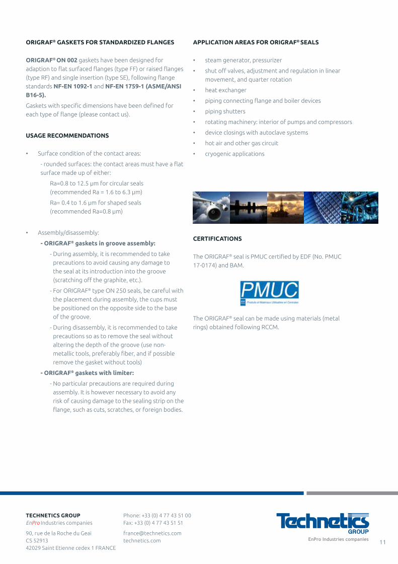
APPLICATION AREAS FOR ORIGRAF® SEALS
• steam generator, pressurizer
• shut off valves, adjustment and regulation in linear
movement, and quarter rotation
• heat exchanger
• piping connecting flange and boiler devices
• piping shutters
• rotating machinery: interior of pumps and compressors
• device closings with autoclave systems
• hot air and other gas circuit
• cryogenic applications
CERTIFICATIONS
The ORIGRAF® seal is PMUC certified by EDF (No. PMUC
17-0174) and BAM.
The ORIGRAF® seal can be made using materials (metal
rings) obtained following RCCM.
Phone: +33 (0) 4 77 43 51 00 Fax: +33 (0) 4 77 43 51 51
[email protected] technetics.com
TECHNETICS GROUPEnPro Industries companies
90, rue de la Roche du Geai CS 52913 42029 Saint Etienne cedex 1 FRANCE
11

CEFIGRAF® JDG SEALS
CEFIGRAF® JDG SEAL CONCEPT
The CEFIGRAF® JDG seal (cut grooved gasket) is made of a metallic support on which sheets of graphite are inserted into machined grooves. The seal is obtained
through the final densification of the graphite when it is
tightened in contact with the mechanical stop (also known as metal-metal contact).
MAIN ADVANTAGES OF CEFIGRAF ® JDG SEAL
• Advantages of metal-metal contact: it consists of
creating a rigid mechanical contact independent of the
active part of the graphite gasket which is thus preserved
against the general mechanical assembly constraints.
The seal's elastic recovery is thus entirely dedicated to
the conservation of the seal. This concept also allows
the seal to be protected from over-tightening.
• No creep, as the graphite is assembled in the groove• The precise machining of the groove makes it possible
to perfectly control the seating pressure on the seal and the densification of the graphite, avoiding all risk of
overweighting
• Monobloc seal, easy to manipulate (no risk of
breakage during manipulation)
• Good sealing due to graphite's expansion
• Very good endurance in terms of thermal transitions
AREA OF USE
(* non associated values)
The maximum conditions for use depend on a number of
parameters, notably the diameter of the seal and the type
of assembly (assembly in a groove or between flat surface
flanges).
CREATION POSSIBILITIES
• Standard: Stainless steel, other metals upon request.
• Possibility of standard flange seals (NF EN
1092-1 - ASME B16.5)
• Shapes: circular, rectangular, elliptic, double strip
and in bars.
Possibility of manufacturing different thicknesses,
depending on the thickness of the components.
TECHNICAL CHARACTERISTICS
• Compression rate: CEFIGRAF® seals are designed with
a total compression rate of between 40 and 50%,
depending on the initial density of the graphite.
• Seating pressure: numerous characterization tests
on the CEFIGRAF® JDG seal have made it possible to
identify the key parameters linked to the performance
of this seal. These make it possible to retain a nominal
sitting pressure of 30 and 50 MPa, for the majority of
applications.
PY0
Metal-metal contact
Sitting pressure MPa
Rated sitting pressure
Tightening
APPLICATION AREAS
• Nuclear: exchangers and openings in manual
tools, valves
• Chemical: exchangers (gaskets with bars), saturated and
heated vapor, hydrocarbons
• Valves: body/bonnet
CERTIFICATIONS
• Option of manufacture with PMUC graphite
(EDF certification No. 17-0172)
INSERTION ASSEMBLY
ASSEMBLY ON FLAT OR ELEVATED SURFACE
Max. continuous temp.
500°C/932°F in oxidizing atmosphere *
Min. temp. -196°C/-320.8°F
Max. pressure 20 MPa *
Roughness of the sealing area
Ra: 1.6 to 12.5 μm (turned surfaces
by lath machining)
Phone: +33 (0) 4 77 43 51 00 Fax: +33 (0) 4 77 43 51 51
[email protected] technetics.com
TECHNETICS GROUPEnPro Industries companies
90, rue de la Roche du Geai CS 52913 42029 Saint Etienne cedex 1 FRANCE
12
CEFIGRAF® JPR SEALS
CEFIGRAF® JPR SEAL CONCEPT
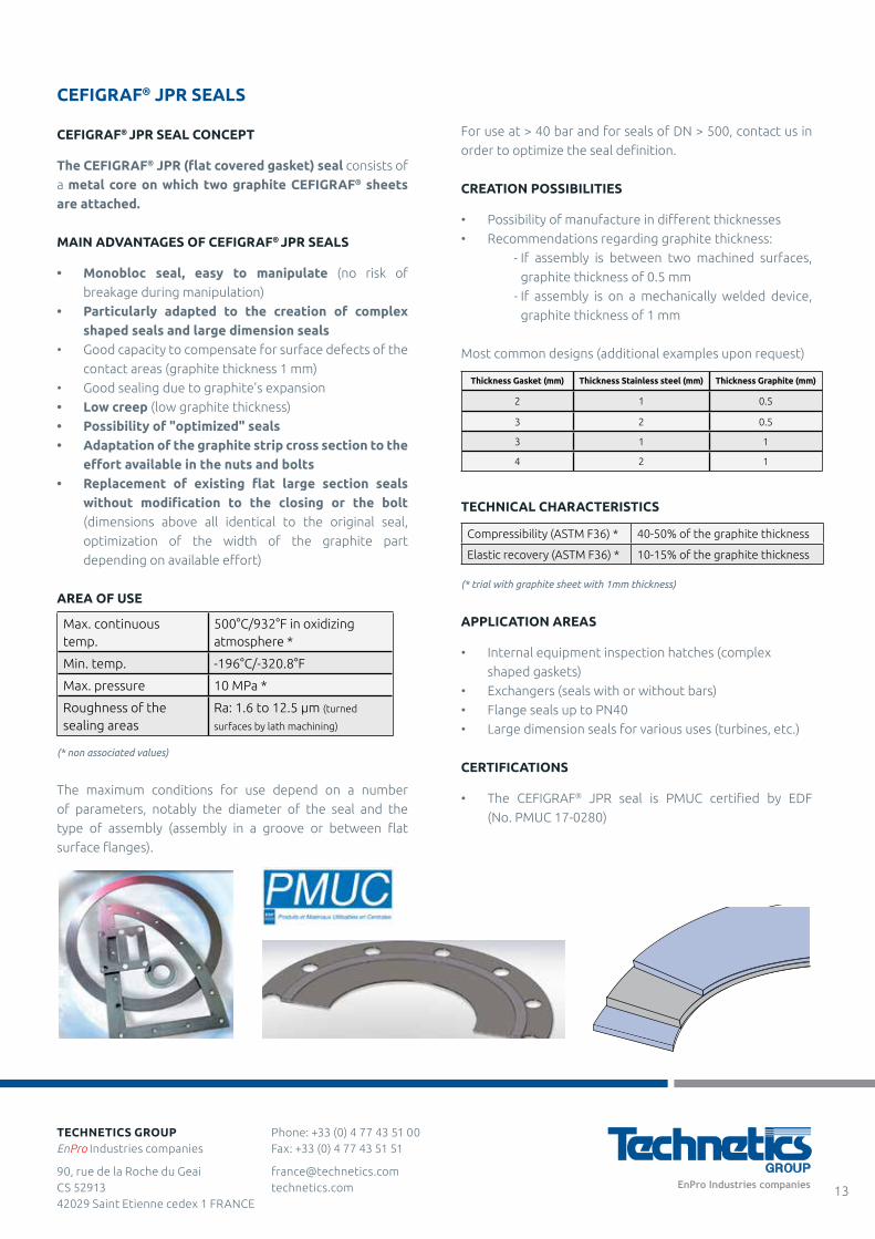
The CEFIGRAF® JPR (flat covered gasket) seal consists of
a metal core on which two graphite CEFIGRAF® sheets are attached.
MAIN ADVANTAGES OF CEFIGRAF® JPR SEALS
• Monobloc seal, easy to manipulate (no risk of
breakage during manipulation)
• Particularly adapted to the creation of complex shaped seals and large dimension seals
• Good capacity to compensate for surface defects of the
contact areas (graphite thickness 1 mm)
• Good sealing due to graphite's expansion
• Low creep (low graphite thickness)
• Possibility of "optimized" seals• Adaptation of the graphite strip cross section to the
effort available in the nuts and bolts• Replacement of existing flat large section seals
without modification to the closing or the bolt (dimensions above all identical to the original seal,
optimization of the width of the graphite part
depending on available effort)
AREA OF USE
Max. continuous temp.
500°C/932°F in oxidizing atmosphere *
Min. temp. -196°C/-320.8°F
Max. pressure 10 MPa *
Roughness of the sealing areas
Ra: 1.6 to 12.5 μm (turned
surfaces by lath machining)
(* non associated values)
The maximum conditions for use depend on a number
of parameters, notably the diameter of the seal and the
type of assembly (assembly in a groove or between flat
surface flanges).
For use at > 40 bar and for seals of DN > 500, contact us in
order to optimize the seal definition.
CREATION POSSIBILITIES
• Possibility of manufacture in different thicknesses
• Recommendations regarding graphite thickness:
- If assembly is between two machined surfaces,
graphite thickness of 0.5 mm
- If assembly is on a mechanically welded device,
graphite thickness of 1 mm
Most common designs (additional examples upon request)
Thickness Gasket (mm) Thickness Stainless steel (mm) Thickness Graphite (mm)
2 1 0.5
3 2 0.5
3 1 1
4 2 1
TECHNICAL CHARACTERISTICS
Compressibility (ASTM F36) * 40-50% of the graphite thickness
Elastic recovery (ASTM F36) * 10-15% of the graphite thickness
(* trial with graphite sheet with 1mm thickness)
APPLICATION AREAS
• Internal equipment inspection hatches (complex
shaped gaskets)
• Exchangers (seals with or without bars)
• Flange seals up to PN40
• Large dimension seals for various uses (turbines, etc.)
CERTIFICATIONS
• The CEFIGRAF® JPR seal is PMUC certified by EDF
(No. PMUC 17-0280)
Phone: +33 (0) 4 77 43 51 00 Fax: +33 (0) 4 77 43 51 51
[email protected] technetics.com
TECHNETICS GROUPEnPro Industries companies
90, rue de la Roche du Geai CS 52913 42029 Saint Etienne cedex 1 FRANCE
13
ORIGRAF® SEALS FOR AUTOCLAVE CLOSURE HEADS
CONCEPT
The principal of this method of closing is to use pressure
to push the autoclave plug and to compress the graphite
radially in the bore of the valve body. The more the pressure
increases, the more the seal is compressed.
There are several types of ORIGRAF® seals for autoclave
closings which can be made up of metal rings (stainless steel,
steel, or other upon request) and molded graphite rings
(straight or cone-shapes) which ensure radial sealing in the
body of the valve as well as on the right of the autoclave plug.
MAIN ADVANTAGES
• No corrosion problems with the STELLITE® deposit
from the device due to the purity of its PMUC grade
graphite (carbon level >99.5%, S and H levels <200ppm)
• Good sealing due to the graphite's increased density
on this type of autoclave assembly
• Good temperature resistance as the mechanical
properties of graphite remain relatively unchanged in
high temperatures
• Good resistance over time due to very low creep• Good capacity to compensate for surface defects of
the contact areas (barrel and plug)
AREA OF USE
(* non associated values)
CREATION POSSIBILITIES
Manufacturing possibilities range from DN 80 to DN 600.
All metal materials are available upon request.
MOST COMMON DESIGNS
APPLICATION AREAS
• Sanitary fitting devices with autoclave closings
• Autoclave closing on various devices: heaters, tanks, etc.
• Energy production (nuclear and thermal plants)
and petrochemical
CERTIFICATIONS
• The ORIGRAF® JPR seal is PMUC certified by EDF
(No. PMUC 17-0174)
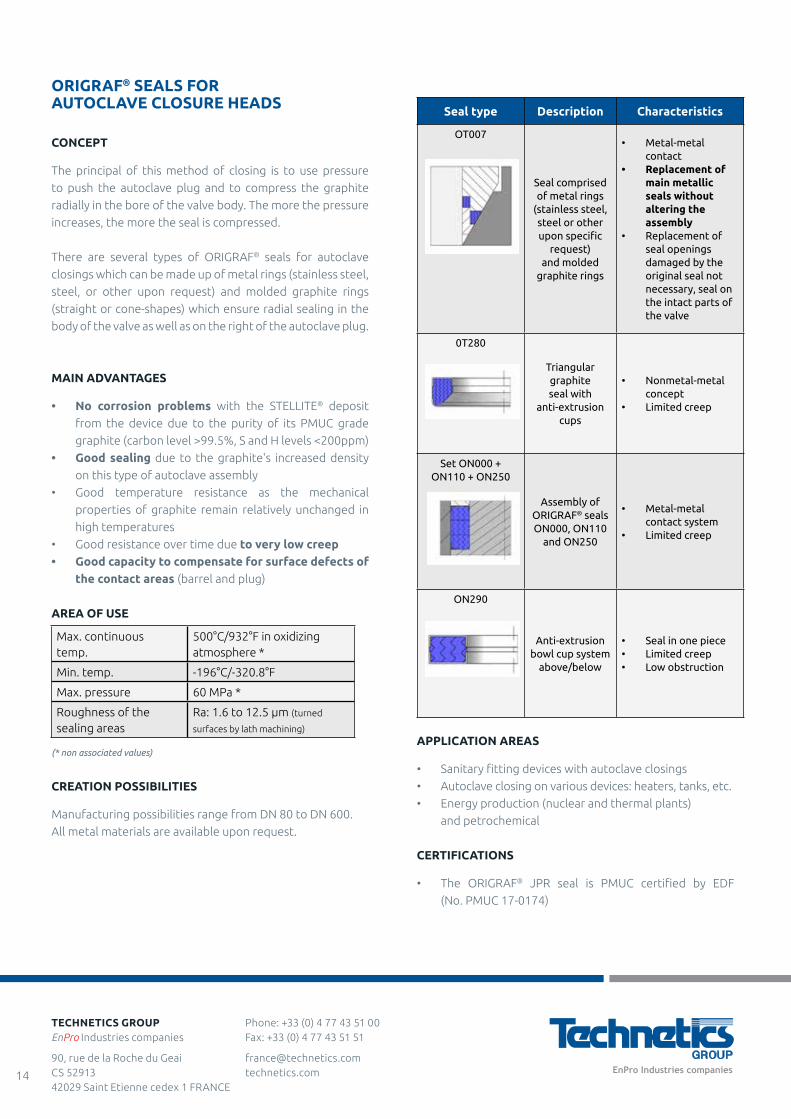
Seal type Description Characteristics
OT007
Seal comprised of metal rings
(stainless steel, steel or other upon specific
request) and molded
graphite rings
• Metal-metal contact
• Replacement of main metallic seals without altering the assembly
• Replacement of seal openings damaged by the original seal not necessary, seal on the intact parts of the valve
0T280
Triangular graphite seal with
anti-extrusion cups
• Nonmetal-metal concept
• Limited creep
Set ON000 + ON110 + ON250
Assembly of ORIGRAF® seals ON000, ON110
and ON250
• Metal-metal contact system
• Limited creep
ON290
Anti-extrusion bowl cup system
above/below
• Seal in one piece• Limited creep• Low obstruction
Max. continuous temp.
500°C/932°F in oxidizing atmosphere *
Min. temp. -196°C/-320.8°F
Max. pressure 60 MPa *
Roughness of the sealing areas
Ra: 1.6 to 12.5 μm (turned
surfaces by lath machining)
Phone: +33 (0) 4 77 43 51 00 Fax: +33 (0) 4 77 43 51 51
[email protected] technetics.com
TECHNETICS GROUPEnPro Industries companies
90, rue de la Roche du Geai CS 52913 42029 Saint Etienne cedex 1 FRANCE
14
Maestral: THE LABORATORY THAT USES SCIENCE TO SERVE SEALING
Maestral offers a multi-scale scientific approach combining tests, characterization and simulation in order to develop sealing solutions that meet present and future needs. Maestral brings together the strengths of Technetics Group, leader in the field of high performance industrial sealing and CEA (French Atomic Energy and Alternative Energy Agency), a major player in research and innovative developments for energy technologies.
Maestral's expertise is the result of a successful collaboration, since 1969 between CEA and Technetics Group. Our skill is constantly growing as a result of the real-life cases we study and our experts have the ability to quickly assess situations in order to offer suitable R&D programs and solutions. Maestral technicians are experienced and certified to COFREND (French Confederation for Non-destructive Testing) II, Leak Testing. Maestral has the latest generation of test and characterisation equipment, offering the ability to quickly and thoroughly analyze the behavior of seals. Simulation does not replace tests on mock-ups but it allows the latter as well as experimental artifacts to be reduced. Simulation is an efficient tool for conceiving and optimizing a sealing system by checking its performance in all circumstances, in order to best respond to clients' issues.
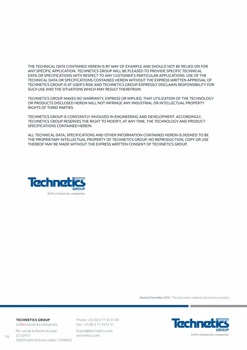
Today, prediction abilities of models are advanced enough to extrapolate life-size results when the size of the mock-ups or the duration of the tests makes them impossible in real conditions. Our FEA engineers are particularly experienced in the mechanics of largely non-linear behaviors, such as deformations, creep, complex contacts with flanges and friction. Maestral is committed to actively developing numerical simulation tools and resources, applied to sealing. In order to develop product lines or for special applications, Maestral designs and develops specific benches or mock-ups reproducing actual operating conditions. To do so, it calls on the advanced analytical skills of CEA and on the manufacturing and research abilities of Technetics Group.
Calculation for finished elements
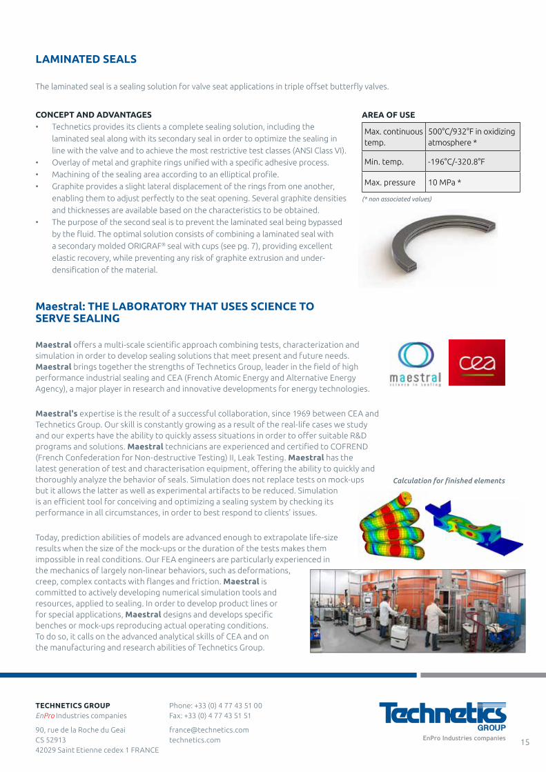
LAMINATED SEALS
The laminated seal is a sealing solution for valve seat applications in triple offset butterfly valves.
Max. continuous temp.
500°C/932°F in oxidizing atmosphere *
Min. temp. -196°C/-320.8°F
Max. pressure 10 MPa *
AREA OF USE
(* non associated values)
CONCEPT AND ADVANTAGES• Technetics provides its clients a complete sealing solution, including the
laminated seal along with its secondary seal in order to optimize the sealing in
line with the valve and to achieve the most restrictive test classes (ANSI Class VI).
• Overlay of metal and graphite rings unified with a specific adhesive process.
• Machining of the sealing area according to an elliptical profile.
• Graphite provides a slight lateral displacement of the rings from one another,
enabling them to adjust perfectly to the seat opening. Several graphite densities
and thicknesses are available based on the characteristics to be obtained.
• The purpose of the second seal is to prevent the laminated seal being bypassed
by the fluid. The optimal solution consists of combining a laminated seal with
a secondary molded ORIGRAF® seal with cups (see pg. 7), providing excellent
elastic recovery, while preventing any risk of graphite extrusion and under-
densification of the material.
Phone: +33 (0) 4 77 43 51 00 Fax: +33 (0) 4 77 43 51 51
[email protected] technetics.com
TECHNETICS GROUPEnPro Industries companies
90, rue de la Roche du Geai CS 52913 42029 Saint Etienne cedex 1 FRANCE
15
Phone: +33 (0) 4 77 43 51 00 Fax: +33 (0) 4 77 43 51 51
[email protected] technetics.com
TECHNETICS GROUPEnPro Industries companies
90, rue de la Roche du Geai CS 52913 42029 Saint Etienne cedex 1 FRANCE
16
THE TECHNICAL DATA CONTAINED HEREIN IS BY WAY OF EXAMPLE AND SHOULD NOT BE RELIED ON FOR ANY SPECIFIC APPLICATION. TECHNETICS GROUP WILL BE PLEASED TO PROVIDE SPECIFIC TECHNICAL DATA OR SPECIFICATIONS WITH RESPECT TO ANY CUSTOMER’S PARTICULAR APPLICATIONS. USE OF THE TECHNICAL DATA OR SPECIFICATIONS CONTAINED HEREIN WITHOUT THE EXPRESS WRITTEN APPROVAL OF TECHNETICS GROUP IS AT USER’S RISK AND TECHNETICS GROUP EXPRESSLY DISCLAIMS RESPONSIBILITY FOR SUCH USE AND THE SITUATIONS WHICH MAY RESULT THEREFROM.
TECHNETICS GROUP MAKES NO WARRANTY, EXPRESS OR IMPLIED, THAT UTILIZATION OF THE TECHNOLOGY OR PRODUCTS DISCLOSED HEREIN WILL NOT INFRINGE ANY INDUSTRIAL OR INTELLECTUAL PROPERTY RIGHTS OF THIRD PARTIES.
TECHNETICS GROUP IS CONSTANTLY INVOLVED IN ENGINEERING AND DEVELOPMENT. ACCORDINGLY, TECHNETICS GROUP RESERVES THE RIGHT TO MODIFY, AT ANY TIME, THE TECHNOLOGY AND PRODUCT SPECIFICATIONS CONTAINED HEREIN.
ALL TECHNICAL DATA, SPECIFICATIONS AND OTHER INFORMATION CONTAINED HEREIN IS DEEMED TO BE THE PROPRIETARY INTELLECTUAL PROPERTY OF TECHNETICS GROUP. NO REPRODUCTION, COPY OR USE THEREOF MAY BE MADE WITHOUT THE EXPRESS WRITTEN CONSENT OF TECHNETICS GROUP.
Revised December 2016 - This document replaces all previous versions

COMPANY:CONTACT:ADDRESS:
END USER:REF INQUIRY:Activity Field: Unit:Type of Apparatus: Connection:
Medium: Gas Liquid VacuumNature: SKETCH
Working Conditions:
Test:
maxThermal Shocks min
Life time:
Existing Designed To Be DefinedDimensions: Standard: Norm: ND:
PN (Lbs): Materials:BOLTS: Nb: M: Pitch:
Drill Diameter: Material:HOUSING: Existing: Changeable:
Type: Flat Face: Raised Face: (Outside Diameter of Raised Face: )Double Tongue & Groove: Single Tongue & Groove:
Other:
Groove: ID: OD : Depth:Tongue: ID: OD : Height:
Ra = µm/Wished:
Other Commercial Information: Issuer:Qty to be Quoted: Yearly Consumption: Date:
OTHERS: Other Technical Information: (For the exchangers, join a drawing of the pass partitions)
Type:Material:
Complementary Information:
Groove:Dimensions: (join a drawing with dimensions)
Surface Finish of Sealing Areas:SEAL: Primarily Used: To Be Defined:
(for non standards assemblies, join a drawing with dimensions)
To Be Defined:
ASSEMBLY
Requested sealing level:
WORKING CONDITIONS:
Pressure Temperature
N°:
DATE:INSTALLATION LOCATION:
FAX:EMAIL:
STATIC SEALS DATA SHEETTel: +33 (0) 4 77 43 51 00 Fax: +33 (0) 4 77 43 51 51
Email: [email protected]:

COMPANY:CUSTOMER:COUNTRY:
END USER:REF INQUIRY:Activity Field: WORKING CONDITIONSUnit: Speed: rpm Pressure (bar)Type of Apparatus: Constant: Suction:Reference: Variable: Discharge:Manufacturer:
MEDIUM Hours/day: min:Gas Liquid Vacuum Days/months: max:
Nature: Months/year:Requested sealing level:
PH: Viscosity: Life time:Density: % Solids:
Existing Designed To Be DefinedDimensions: Standard: Norm:Type of Assembly: Single: External: Rotating: Adjustable:
Double: Internal: Fixed: Cartridge:SHAFT METER:HOUSING: Existing: Changeable:
Diameter:Available axial space:
Compatible RINGS SECONDARY SEALSMaterials Steel: Carbon: Nitrile:
Stainless steel: Tungsten carbide: EP:Other: SiC: Viton:
AI2O3: PTFE:Other: Other:
Wished:
Other Technical Information:
Other Commercial Information: Issuer:Qty to be Quoted: Yearly Consumption: Date:
SEMI-DYNAMIC SEALS DATA SHEETTel: +33 (0) 4 77 43 51 00 Fax: +33 (0) 4 77 43 51 51
Email: [email protected]:FAX:EMAIL:DATE:INSTALLATION LOCATION:N°:
Operating Cycle Temperature (°C)
SUPPORTS/SPRINGS
ASSEMBLY
Sleeve Diameter:To Be Defined:
MECHANICAL SEAL: Primarily Used: To Be Defined:Trademark/Type:
Material:Reference of enclosed drawings:
OTHERS:


TECHNETICS GROUPEnPro Industries companies
[email protected] technetics.com
For more information on how Technetics Group affects your critical markets, visit technetics.com.
ASIA
Blk 203, #05-52 Woodlands Avenue 9 Woodlands Spectrum 2, 738956 Singapore
Phone: +65 6759 2335 Fax: +65 6759 7319
FRANCE
90, rue de la Roche du Geai CS 52913 42029 Saint Etienne cedex 1 FRANCE
Phone: +33 (0) 4 77 43 51 00 Fax: +33 (0) 4 77 43 51 51
49 Avenue Charles de Gaulle Z.I. Survaure 42607 Montbrison cedex FRANCE
Phone: +33 (0) 4 77 96 79 80
GERMANY
Falkenweg 1 41468 Neuss Germany
Phone: 0800-627-0151
UK
Acan Way, Coventry Road Narborough, Leicester LE19 2FT UK
Phone: +44 (0) 1162 727411 Fax: +44 (0) 1162 727412
USA
2791 The Boulevard Columbia, SC 29209 USA
Phone: +1-803-783-1880 Fax: +1-803-783-4279
305 Fentress Boulevard Daytona Beach, FL 32114 USA
Phone: +1-386-253-0628 Fax: +1-386-257-0122
1700 E. International Speedway Blvd DeLand, FL 32724 USA
Phone: +1-386-736-7373 Fax: +1-386-738-4533
1600 Industry Road Hatfield, PA 19440 USA
Phone: +1-800-618-4701 Fax: +1-215-855-3570
10633 W Little York, Bldg 3, Suite 300 Houston, TX 77041 USA
Phone: +1-713-983-4201 Fax: +1-713-466-3721
10 Old Webster Road Oxford, MA 01540 USA
Phone: +1-508-987-5900
990 Richard Avenue, Suite 117 Santa Clara, CA 95050 USA
Phone: +1-669-242-8804 Fax: +1-669-242-8492


