52
WWW.PI.WS PRECISE Parallel Kinematics HEXAPOD SYSTEMS WITH 6 DOF AND NANOMETER RESOLUTION FLEXIBLE RELIABLE

W W W. P I . W S
P R E C I S E
Parallel KinematicsH E X A P O D S Y S T E M S W I T H 6 D O F A N D N A N O M E T E R R E S O L U T I O N
F L E X I B L E
R E L I A B L E

2
W W W. P I . W S
Contents
PRODUCTS: HEXAPOD AND SPACEFAB . . . . . . . . . . . . . . . . . . . . . . . . . . . . . . . . . . . . . . . . . . 3
Precision of Below One Micrometer H-850 6-Axis Hexapod for Loads up to 250 kg . . . . . . . . . . . . . . . . . . . . . . . . . . . . . . . . . . 8 H-811 .D2 6-Axis Miniature Hexapod . . . . . . . . . . . . . . . . . . . . . . . . . . . . . . . . . . . . . . . . . 16 H-810 6-Axis Miniature Hexapod . . . . . . . . . . . . . . . . . . . . . . . . . . . . . . . . . . . . . . . . . . . . 24 H-206 6-Axis Precision Alignment System . . . . . . . . . . . . . . . . . . . . . . . . . . . . . . . . . . . . 18 P-911KNMV UHV-Compatible Miniature Piezo Hexapod . . . . . . . . . . . . . . . . . . . . . . . . . 31 SF-3000 BS SpaceFAB, Low Profile . . . . . . . . . . . . . . . . . . . . . . . . . . . . . . . . . . . . . . . . . . 20 SF-6500 PS SpaceFAB, Compact . . . . . . . . . . . . . . . . . . . . . . . . . . . . . . . . . . . . . . . . . . . . 26 Q-845 Q-Motion SpaceFAB Micro Robot . . . . . . . . . . . . . . . . . . . . . . . . . . . . . . . . . . . . . . 28 Q-821 Q-Motion Miniature SpaceFAB Robot . . . . . . . . . . . . . . . . . . . . . . . . . . . . . . . . . . . 29
High Loads from 100 kg to 2 Tons H-845 High-Load Hexapod for Loads up to 1000 kg . . . . . . . . . . . . . . . . . . . . . . . . . . . . . . 4 H-850 6-Axis Hexapod for Loads up to 250 kg . . . . . . . . . . . . . . . . . . . . . . . . . . . . . . . . . . 8 H-850KMLD High-Load Hexapod for Loads up to 500 kg . . . . . . . . . . . . . . . . . . . . . . . . . . 6 H-850KHLC Precision Hexapod for High Loads . . . . . . . . . . . . . . . . . . . . . . . . . . . . . . . . . 32 M-850KWAH Weather-Resistant Hexapod for Astronomy . . . . . . . . . . . . . . . . . . . . . . . . 31
High Vacuum and Special Ambient Conditions H-811 6-Axis Miniature Hexapod . . . . . . . . . . . . . . . . . . . . . . . . . . . . . . . . . . . . . . . . . . . . 16 H-850 6-Axis Hexapod for Loads up to 250 kg . . . . . . . . . . . . . . . . . . . . . . . . . . . . . . . . . . 8 H-824 6-Axis Hexapod, Low Profile . . . . . . . . . . . . . . . . . . . . . . . . . . . . . . . . . . . . . . . . . . 12 H-850KHLC Precision Hexapod for High Loads . . . . . . . . . . . . . . . . . . . . . . . . . . . . . . . . . 32 P-911KNMV UHV-Compatible Miniature Piezo Hexapod . . . . . . . . . . . . . . . . . . . . . . . . . 31 Q-845 Q-Motion SpaceFAB Micro Robot . . . . . . . . . . . . . . . . . . . . . . . . . . . . . . . . . . . . . . 28 Q-821 Q-Motion Miniature SpaceFAB Robot . . . . . . . . . . . . . . . . . . . . . . . . . . . . . . . . . . . 29
Dynamic Motion and Scanning H-860KMAG High-Dynamics Hexapod . . . . . . . . . . . . . . . . . . . . . . . . . . . . . . . . . . . . . . . 22 H-900KSCO Fast 6-Axis Hexapod . . . . . . . . . . . . . . . . . . . . . . . . . . . . . . . . . . . . . . . . . . . . 30 H-840 6-Axis Hexapod, High Velocity . . . . . . . . . . . . . . . . . . . . . . . . . . . . . . . . . . . . . . . . . 10 H-820 6-Axis Positioner with Controller, Standard Class . . . . . . . . . . . . . . . . . . . . . . . . . 14 P-915KWEF Piezo Hexapod . . . . . . . . . . . . . . . . . . . . . . . . . . . . . . . . . . . . . . . . . . . . . . . . . 32
Cost-Efficient Hexapod Systems for Automation H-840 6-Axis Hexapod, High Velocity . . . . . . . . . . . . . . . . . . . . . . . . . . . . . . . . . . . . . . . . . 10 H-824 6-Axis Hexapod, Low Profile . . . . . . . . . . . . . . . . . . . . . . . . . . . . . . . . . . . . . . . . . . 12 H-820 6-Axis Positioner with Controller, Standard Class . . . . . . . . . . . . . . . . . . . . . . . . . 14 H-206 6-Axis Precision Alignment System . . . . . . . . . . . . . . . . . . . . . . . . . . . . . . . . . . . . 18
Coordinated Motion Control and Adaptable Software C-887 .5x Controller for Hexapod Positioning Systems . . . . . . . . . . . . . . . . . . . . . . . . . . 34
Accessories . . . . . . . . . . . . . . . . . . . . . . . . . . . . . . . . . . . . . . . . . . . . . . . . . . . . . . . . . . . . . . . . 33
KEY TECHNOLOGIES . . . . . . . . . . . . . . . . . . . . . . . . . . . . . . . . . . . . . . . . . . . . . . . . . . . . . . . . 36
Drive Technology Comparison . . . . . . . . . . . . . . . . . . . . . . . . . . . . . . . . . . . . . . . . . . . . . . 37 Parallel Kinematic Positioning Systems . . . . . . . . . . . . . . . . . . . . . . . . . . . . . . . . . . . . . . 38 Hexapods in Automation . . . . . . . . . . . . . . . . . . . . . . . . . . . . . . . . . . . . . . . . . . . . . . . . . . 41 Hexapod as Motion Simulator . . . . . . . . . . . . . . . . . . . . . . . . . . . . . . . . . . . . . . . . . . . . . . 42 Active Vibration Damping Control-Loop . . . . . . . . . . . . . . . . . . . . . . . . . . . . . . . . . . . . . . 43 Motion Control Software . . . . . . . . . . . . . . . . . . . . . . . . . . . . . . . . . . . . . . . . . . . . . . . . . . 44 Programming . . . . . . . . . . . . . . . . . . . . . . . . . . . . . . . . . . . . . . . . . . . . . . . . . . . . . . . . . . . . 46 Hexapod-Specific Software . . . . . . . . . . . . . . . . . . . . . . . . . . . . . . . . . . . . . . . . . . . . . . . . 47
THE PI GROUP • MILESTONES . . . . . . . . . . . . . . . . . . . . . . . . . . . . . . . . . . . . . . . . . . . . . . . . . 48
Product Overview . . . . . . . . . . . . . . . . . . . . . . . . . . . . . . . . . . . . . . . . . . . . . . . . . . . . . . . . . . . 50
© Physik Instrumente (PI) GmbH & Co . KG
Although the information in this document has been compiled with the greatest care, errors cannot be ruled out completely .
Therefore, we cannot guar-antee for the information being complete, correct and up to date . Illustrations may differ from the original and are not binding . PI reserves the right to supplement or change the information pro-vided without prior notice .

3
P I | H E X A P O D S
ProductsH E X A P O D A N D S P A C E F A B

4
W W W. P I . W SW W W . P I . W S
High-Load HexapodP O S I T I O N I N G 1 T O N W I T H M I C R O M E T E R P R E C I S I O N
H-845 Load capacity to 1000 kg
Velocity to 50 mm/s
Repeatability to ±0 .5 µm
Travel ranges to 340 mm / 60°
Scalable design: Dimensions, travel ranges and loads
Actuator resolution to 40 nm
Drive: brushless motors with brake
Sophisticated controller using vec-tor algorithms, virtual pivot point
Extensive software support
Reference-class 6-axis positioning systemParallel-kinematic design for six degrees of freedom making it signifi cantly more compact and stiff than serial-kinematic systems, higher dynamic range, no moved cables: Higher reliability, reduced friction . Large clear aperture . Brushless DC motors with brakes
Rapid implementation of customer requestsThe high-load Hexapod has a modular structure and uses a set of different modules for drive unit and joint . The platforms can be adapted to the customer‘s application . This allows for rapid implementation of special customer requirements
Powerful digital controller, open software architecture6D vector motion controller for Hexapods, incl . two additional servo axes . Arbitrary, stable pivot point, soft-ware-selectable . Positions commanded in Cartesian coordinates . Macro command language . Open-source LabVIEW driver and libraries . Determination of the work-space . Virtual machine for Hexapod emulation . Optional: Software for avoiding collisions in restricted workspace
©P
hysi
k In
stru
men
te (
PI)
Gm
bH
& C
o. K
G 2
015.
Su
bje
ct t
o c
han
ge
wit
ho
ut
no
tice
. Lat
est
rele
ases
ava
ilab
le a
t w
ww
.pi .w
s . R
1 15
/05/
21 .0
Fields of applicationResearch and industry . For astronomy, aviation and aerospace

5
P I | H E X A P O D SW W W . P I . W S
H-845 .D11, H-845 .D31, H-845 .D51 Hexapod, dimensions in mm
Preliminary Data H-845.D11 H-845.D21 H-845.D31 H-845.D41 H-845.D51 H-845.D61 Unit Tolerance
Active axes X, Y, Z, θX, θY,θZ
X, Y, Z, θX, θY,θZ
X, Y, Z, θX, θY,θZ
X, Y, Z, θX, θY,θZ
X, Y, Z, θX, θY,θZ
X, Y, Z, θX, θY,θZ
Motion and positioning
Travel range* X, Y ±110 ±170 ±110 ±170 ±110 ±170 mm
Travel range* Z ±50 ±105 ±50 ±105 ±50 ±105 mm
Travel range* θX, θY ±15 ±20 ±15 ±20 ±15 ±20 °
Travel range* θZ ±30 ±30 ±30 ±30 ±30 ±30 °
Single-actuator design resolution 0 .04 0 .04 0 .08 0 .08 0 .1 0 .1 µm
Min . incremental motion X, Y 1 1 2 2 2 .5 2 .5 µm typ .
Min . incremental motion Z 0 .5 0 .5 1 1 1 1 µm typ .
Min . incremental motion θX, θY, θZ 15 15 30 30 30 30 µrad typ .
Backlash X, Y 5 5 10 10 10 10 µm typ .
Backlash Z 1 1 2 2 2 2 µm typ .
Backlash θX, θY 15 15 30 30 30 30 µrad typ .
Backlash θZ 30 30 60 60 60 60 µrad typ .
Repeatability X, Y ±2 ±2 ±4 ±4 ±5 ±5 µm typ .
Repeatability Z ±0 .5 ±0 .5 ±1 ±1 ±2 ±2 µm typ .
Repeatability θX, θY, θZ ±10 ±10 ±20 ±20 ±25 ±25 µrad typ .
Max . velocity X, Y, Z 20 20 40 40 50 50 mm/s
Max . velocity θX, θY, θZ 50 50 100 100 120 120 mrad/s
Typ . Velocity X, Y, Z 10 10 20 20 25 25 mm/s
Typ . Velocity θX, θY, θZ 20 20 40 40 50 50 mrad/s
Mechanical properties
Load (base plate horizontal / anyorientation)
1000 / 300 1000 / 300 500 / 150 500 / 150 400 / 120 400 / 120 kg max .
Motor type Brushless DC motor
Brushless DC motor
Brushless DC motor
Brushless DC motor
Brushless DC motor
Brushless DC motor
Miscellaneous
Operating temperature range -10 to 50 -10 to 50 -10 to 50 -10 to 50 -10 to 50 -10 to 50 °C
Material Aluminum Aluminum Aluminum Aluminum Aluminum Aluminum
Mass 120 150 120 150 120 150 kg ±5 %
Cable length 9 9 9 9 9 9 m ±10 mm
Controller
Included in delivery C-887 C-887 C-887 C-887 C-887 C-887
Technical data specifi ed at 20 ±3°C . Ask about custom designs!* The travel ranges of the individual coordinates (X, Y, Z, θX, θY, θZ ) are interdependent . The data for each axis in this table shows its maximum travel, where all other axes
are at their zero positions . If the other linear or rotational coordinates are not zero, the available travel may be less .
©P
hysi
k In
stru
men
te (
PI)
Gm
bH
& C
o. K
G 2
015.
Su
bje
ct t
o c
han
ge
wit
ho
ut
no
tice
. Lat
est
rele
ases
ava
ilab
le a
t w
ww
.pi .w
s . R
1 15
/05/
21 .0

6
W W W. P I . W SW W W . P I . W S
High-Load HexapodH I G H - P R E C I S I O N A N D R E P E ATA B L E P O S I T I O N I N G
H-850KMLD Load capacity to 500 kg
Min. incremental motion 1 µm (X, Y), 0.5 µm (Z)
Travel ranges to 100 mm / 60°
Optionally with absolute encoders
© P
hys
ik In
stru
men
te (
PI)
Gm
bH
& C
o . K
G 2
015 .
Su
bje
ct t
o c
han
ge
wit
ho
ut
no
tice
. Lat
est
rele
ases
ava
ilab
le a
t w
ww
.pi .w
s . R
1 14
/08/
18 .0
Reference-class 6-axis positioning systemParallel-kinematic design for six degrees of freedom making it signifi cantly more compact and stiff than serial-kinematic systems, higher dynamic range, no moved cables: Higher reliability, reduced friction. Large clear aperture
Optional feature: Absolute position measurementOptionally, the position is measured using absolute encoders. The exact position of the axes is determined after the Hexapod has been switched on. A reference move is not necessary
Powerful digital controller, open software architecture6D vector motion controller for Hexapods, plus two
Fields of applicationResearch and industry. For astronomy, aviation and aerospace
additional servo axes. Arbitrary, stable pivot point, software-selectable. Positions commanded in Cartesian coordinates. Macro command language. Open-source LabVIEW driver and libraries. Determination of the workspace. Virtual machine for Hexapod emulation. Optional: Software for avoiding collisions in restricted workspace

7
P I | H E X A P O D SW W W . P I . W S
© P
hys
ik In
stru
men
te (
PI)
Gm
bH
& C
o. K
G 2
015.
Su
bje
ct t
o c
han
ge
wit
ho
ut
no
tice
. Lat
est
rele
ases
ava
ilab
le a
t w
ww
.pi.w
s. R
1 14
/08/
18.0
Preliminary Data H-850KMLD H-850KMLA Unit Tolerance
Active axes X, Y, Z, θX, θY, θZ X, Y, Z, θX, θY, θZ
Motion and positioning
Travel range* X, Y ±50 ±50 mm
Travel range* Z ±25 ±25 mm
Travel range* θX, θY±15 ±15 °
Travel range* θZ±30 ±30 °
Min. incremental motion X, Y 1 0.5 µm typ.
Min. incremental motion Z 0.5 0.2 µm typ.
Min. incremental motion θX, θY, θZ5 2.5 µrad typ.
Backlash X, Y 4 2.5 µm typ.
Backlash Z 1 0.7 µm typ.
Backlash θX, θY15 10 µrad typ.
Backlash θZ30 20 µrad typ.
Repeatability X, Y ±1 ±1 µm typ.
Repeatability Z ±0.3 ±0.3 µm typ.
Repeatability θX, θY±5 ±5 µrad typ.
Repeatability θZ±9 ±9 µrad typ.
Max. velocity X, Y, Z 0.5 0.5 mm/s
Max. velocity θX, θY, θZ6 6 mrad/s
Typ. velocity X, Y, Z 0.3 0.3 mm/s
Typ. velocity θX, θY, θZ3 3 mrad/s
Mechanical properties
Load (base plate horizontal / any orientation)
500 / 200 500 / 200 kg max.
Holding force, de-energized (base plate horizontal / any orientation)
4000 / 2000 4000 / 2000 N max.
Motor type DC gear motor DC gear motor
Miscellaneous
Operating temperature range -10 to 50 -10 to 50 °C
Material Aluminum Aluminum
Dimensions Base plate Ø 370 Moving platform Ø 280 Clear aperture Ø 100 Hexapod height in center position 350
Base plate Ø 370 Moving platform Ø 280 Clear aperture Ø 100 Hexapod height in center position 350
mm ±10 mm
Mass 20 25 kg
Cable length 3 3 m ±10 mm
Technical data specified at 20 ±3 °C.Ask about custom designs!* The travel ranges of the individual coordinates (X, Y, Z, θX, θY, θZ) are interdependent. The data for each axis in this table shows its maximum travel,
where all other axes are at their zero positions. If the other linear or rotational coordinates are not zero, the available travel may be less.
H-850.KMLD, dimensions in mm

8
W W W. P I . W SW W W . P I . W S
©P
hysi
k In
stru
men
te (
PI)
Gm
bH
& C
o. K
G 2
015.
Su
bje
ct t
o c
han
ge
wit
ho
ut
no
tice
. Lat
est
rele
ases
ava
ilab
le a
t w
ww
.pi .w
s . R
1 15
/05/
21 .0
6-Axis HexapodFOR LOADS OF UP TO 250 KG
H-850 Load capacity to 250 kg
Repeatability to ±0 .2 µm
Travel ranges to 100 mm / 60°
Actuator resolution to 5 nm
MTBF 20,000 h
Works in any orientation
Linear and rotary multi-axis scans
Vacuum-compatible versions available
Sophisticated controller using vector algorithms, virtual pivot point
Comprehensive software package
Reference-class 6-axis positioning systemParallel-kinematic design for six degrees of freedom making it signifi cantly more compact and stiff than serial-kinematic systems, higher dynamic range, no moved cables: Higher reliability, reduced friction . Vacuum-compatible versions to 10-6 hPa are available
Drive variantsH-850 .Hxx with DC gear motors for heavy loadsH-850 .Gxx with powerful DC motors for higher velocity . Heavy-duty, ultra-high-resolution bearings for 24/7 applications
Powerful digital controller, open software architectureUser-defi ned, stable pivot point, software-selectable . Positions commanded in Cartesian coordinates . Macro programming . Open source LabVIEW driver set . Work space simulation software . Virtual Hexapod machine software . Optional: Collision avoidance software (external obstacles) .
Hexapods are by default confi gured and delivered as a system including a controller
C-887 .52 compact bench-top controller for a lower system price . Digital I/ O interfaces, e .g . for external triggering
C-887 .11 19" controller, comprises the control for two additional single axes with servo motors . Options: Control of piezo axes, photometer cards for visible light or infrared light range
Fields of applicationResearch and industry, standard and vacuum environ-ments . For astronomy, optics positioning, aviation and aerospace
9
P I | H E X A P O D SW W W . P I . W S
©P
hysi
k In
stru
men
te (
PI)
Gm
bH
& C
o. K
G 2
015.
Su
bje
ct t
o c
han
ge
wit
ho
ut
no
tice
. Lat
est
rele
ases
ava
ilab
le a
t w
ww
.pi .w
s . R
1 15
/05/
21 .0
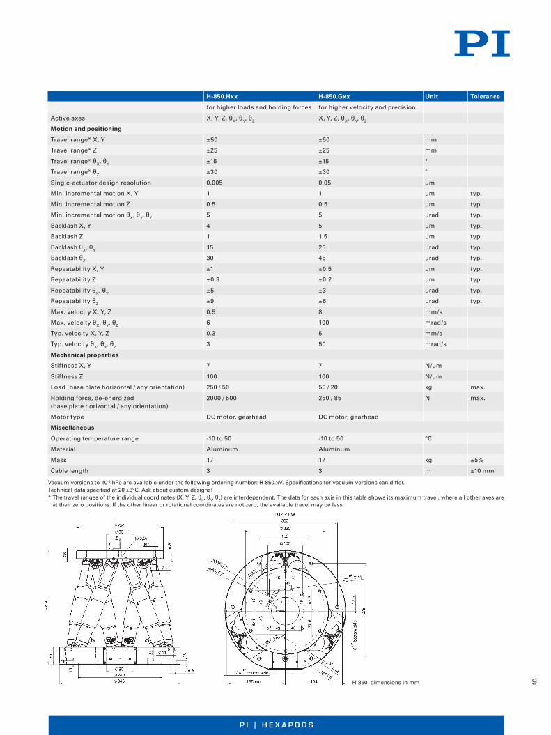
H-850.Hxx H-850.Gxx Unit Tolerance
for higher loads and holding forces for higher velocity and precision
Active axes X, Y, Z, θX, θY, θZ X, Y, Z, θX, θY, θZ
Motion and positioning
Travel range* X, Y ±50 ±50 mm
Travel range* Z ±25 ±25 mm
Travel range* θX, θY ±15 ±15 °
Travel range* θZ ±30 ±30 °
Single-actuator design resolution 0 .005 0 .05 µm
Min . incremental motion X, Y 1 1 µm typ .
Min . incremental motion Z 0 .5 0 .5 µm typ .
Min . incremental motion θX, θY, θZ 5 5 µrad typ .
Backlash X, Y 4 5 µm typ .
Backlash Z 1 1 .5 µm typ .
Backlash θX, θY 15 25 µrad typ .
Backlash θZ 30 45 µrad typ .
Repeatability X, Y ±1 ±0 .5 µm typ .
Repeatability Z ±0 .3 ±0 .2 µm typ .
Repeatability θX, θY ±5 ±3 µrad typ .
Repeatability θZ ±9 ±6 µrad typ .
Max . velocity X, Y, Z 0 .5 8 mm/s
Max . velocity θX, θY, θZ 6 100 mrad/s
Typ . velocity X, Y, Z 0 .3 5 mm/s
Typ . velocity θX, θY, θZ 3 50 mrad/s
Mechanical properties
Stiffness X, Y 7 7 N/µm
Stiffness Z 100 100 N/µm
Load (base plate horizontal / any orientation) 250 / 50 50 / 20 kg max .
Holding force, de-energized 2000 / 500 250 / 85 N max .(base plate horizontal / any orientation)
Motor type DC motor, gearhead DC motor, gearhead
Miscellaneous
Operating temperature range -10 to 50 -10 to 50 °C
Material Aluminum Aluminum
Mass 17 17 kg ±5%
Cable length 3 3 m ±10 mm
Vacuum versions to 10-6 hPa are available under the following ordering number: H-850 .xV . Specifi cations for vacuum versions can differ . Technical data specifi ed at 20 ±3°C . Ask about custom designs!* The travel ranges of the individual coordinates (X, Y, Z, θX, θY, θZ) are interdependent . The data for each axis in this table shows its maximum travel, where all other axes are
at their zero positions . If the other linear or rotational coordinates are not zero, the available travel may be less .
H-850, dimensions in mm
10
W W W. P I . W SW W W . P I . W S
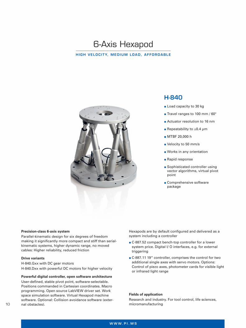
6-Axis HexapodHIGH VELOC ITY, MED IUM LOAD, AFFORDABLE
H-840 Load capacity to 30 kg
Travel ranges to 100 mm / 60°
Actuator resolution to 16 nm
Repeatability to ±0 .4 µm
MTBF 20,000 h
Velocity to 50 mm/s
Works in any orientation
Rapid response
Sophisticated controller using vector algorithms, virtual pivot point
Comprehensive software package
Precision-class 6-axis systemParallel-kinematic design for six degrees of freedom making it signifi cantly more compact and stiff than serial-kinematic systems, higher dynamic range, no moved cables: Higher reliability, reduced friction
Drive variantsH-840 .Gxx with DC gear motorsH-840 .Dxx with powerful DC motors for higher velocity
Powerful digital controller, open software architectureUser-defi ned, stable pivot point, software-selectable . Positions commanded in Cartesian coordinates . Macro programming . Open source LabVIEW driver set . Work space simulation software . Virtual Hexapod machine software . Optional: Collision avoidance software (exter-nal obstacles) .
Hexapods are by default confi gured and delivered as a system including a controller
C-887 .52 compact bench-top controller for a lower system price . Digital I/ O interfaces, e .g . for external triggering
C-887 .11 19“ controller, comprises the control for two additional single axes with servo motors . Options: Control of piezo axes, photometer cards for visible light or infrared light range
Fields of applicationResearch and industry . For tool control, life sciences, micromanufacturing P
hys
ik In
stru
men
te (
PI)
Gm
bH
& C
o . K
G 2
015 .
Su
bje
ct t
o c
han
ge
wit
ho
ut
no
tice
. Lat
est
rele
ases
ava
ilab
le a
t w
ww
.pi .w
s . R
2 15
/05/
20 .0
11
P I | H E X A P O D SW W W . P I . W S
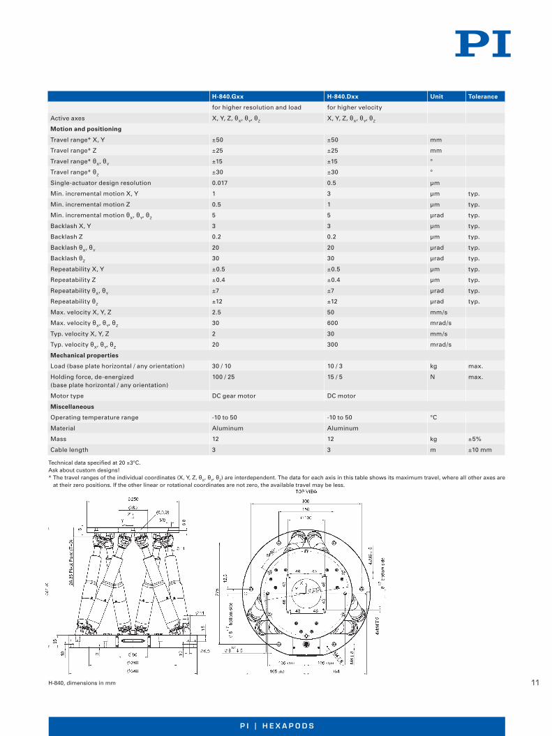
H-840.Gxx H-840.Dxx Unit Tolerance
for higher resolution and load for higher velocity
Active axes X, Y, Z, θX, θY, θZ X, Y, Z, θX, θY, θZ
Motion and positioning
Travel range* X, Y ±50 ±50 mm
Travel range* Z ±25 ±25 mm
Travel range* θX, θY ±15 ±15 °
Travel range* θZ ±30 ±30 °
Single-actuator design resolution 0 .017 0 .5 µm
Min . incremental motion X, Y 1 3 µm typ .
Min . incremental motion Z 0 .5 1 µm typ .
Min . incremental motion θX, θY, θZ 5 5 µrad typ .
Backlash X, Y 3 3 µm typ .
Backlash Z 0 .2 0 .2 µm typ .
Backlash θX, θY 20 20 µrad typ .
Backlash θZ 30 30 µrad typ .
Repeatability X, Y ±0 .5 ±0 .5 µm typ .
Repeatability Z ±0 .4 ±0 .4 µm typ .
Repeatability θX, θY ±7 ±7 µrad typ .
Repeatability θZ ±12 ±12 µrad typ .
Max . velocity X, Y, Z 2 .5 50 mm/s
Max . velocity θX, θY, θZ 30 600 mrad/s
Typ . velocity X, Y, Z 2 30 mm/s
Typ . velocity θX, θY, θZ 20 300 mrad/s
Mechanical properties
Load (base plate horizontal / any orientation) 30 / 10 10 / 3 kg max .
Holding force, de-energized 100 / 25 15 / 5 N max .(base plate horizontal / any orientation)
Motor type DC gear motor DC motor
Miscellaneous
Operating temperature range -10 to 50 -10 to 50 °C
Material Aluminum Aluminum
Mass 12 12 kg ±5%
Cable length 3 3 m ±10 mm
Technical data specifi ed at 20 ±3°C .Ask about custom designs!* The travel ranges of the individual coordinates (X, Y, Z, θX, θY, θZ) are interdependent . The data for each axis in this table shows its maximum travel, where all other axes are
at their zero positions . If the other linear or rotational coordinates are not zero, the available travel may be less .
H-840, dimensions in mm Ph
ysik
Inst
rum
ente
(P
I) G
mb
H &
Co
. KG
201
5 . S
ub
ject
to
ch
ang
e w
ith
ou
t n
oti
ce . L
ates
t re
leas
es a
vaila
ble
at
ww
w .p
i .ws .
R2
15/0
5/20
.0

12
W W W. P I . W SW W W . P I . W S
©P
hysi
k In
stru
men
te (
PI)
Gm
bH
& C
o. K
G 2
015.
Su
bje
ct t
o c
han
ge
wit
ho
ut
no
tice
. Lat
est
rele
ases
ava
ilab
le a
t w
ww
.pi .w
s . R
2 15
/05/
19 .0
6-Axis HexapodLOW-PROF ILE , PREC IS ION PARALLEL -K INEMAT IC SYSTEM
H-824 Load capacity to 10 kg,
self-locking version
Travel ranges to 45 mm / 25°
Actuator resolution to 7 nm
Min . incremental motion to 0 .3 µm
Repeatability to ±0 .1 µm / ±2 .5 µrad
Velocity up to 25 mm/s
Vacuum-compatible versions available
Sophisticated controller using vector algorithms, virtual pivot point
Comprehensive software package
Precision-class 6-axis positioning systemParallel-kinematic design for six degrees of freedom making it signifi cantly more compact and stiff than serial-kinematic systems, higher dynamic range, no moved cables: Higher reliability, reduced friction . Vacuum-compatible versions to 10-6 hPa are available
Compact due to folded drive designH-824 .Gxx with DC gear motorsH-824 .Dxx with powerful DC motors for higher velocity
Powerful digital controller, open software architectureUser-defi ned, stable pivot point, software-selectable . Positions commanded in Cartesian coordinates . Macro programming . Open source LabVIEW driver set . Work space simulation software . Virtual Hexapod machine software . Optional: Collision avoidance software (external obstacles) .
Hexapods are by default confi gured and delivered as a system including a controller
C-887 .52 compact bench-top controller for a lower system price . Digital I/O interfaces, e .g . for external triggering
C-887 .11 19" controller, comprises the control for two additional single axes with servo motors . Options: Control of piezo axes, photometer cards for visible light or infrared light range
Fields of applicationResearch and industry, standard and vacuum environ-ments . For micromanipulation, biotechnology, semicon-ductor manufacturing

13
P I | H E X A P O D SW W W . P I . W S
©P
hysi
k In
stru
men
te (
PI)
Gm
bH
& C
o. K
G 2
015.
Su
bje
ct t
o c
han
ge
wit
ho
ut
no
tice
. Lat
est
rele
ases
ava
ilab
le a
t w
ww
.pi .w
s . R
2 15
/05/
19 .0
H-824.Gxx H-824.Dxx Unit Tolerance
for higher resolution and load for higher velocity
Active axes X, Y, Z, θX, θY, θZ X, Y, Z, θX, θY, θZ
Motion and positioning
Travel range* X, Y ±22 .5 ±22 .5 mm
Travel range* Z ±12 .5 ±12 .5 mm
Travel range* θX, θY ±7 .5 ±7 .5 °
Travel range* θZ ±12 .5 ±12 .5 °
Single-actuator design resolution 0 .007 0 .5 µm
Min . incremental motion X, Y, Z 0 .3 1 µm typ .
Min . incremental motion θX, θY, θZ 3 .5 12 µrad typ .
Backlash X, Y 3 1 µm typ .
Backlash Z 1 1 µm typ .
Backlash θX, θY 20 15 µrad typ .
Backlash θZ 25 25 µrad typ .
Repeatability X, Y ±0 .5 ±0 .5 µm typ .
Repeatability Z ±0 .1 ±0 .1 µm typ .
Repeatability θX, θY ±2 ±2 µrad typ .
Repeatability θZ ±2 .5 ±2 .5 µrad typ .
Max . velocity X, Y, Z 1 25 mm/s
Max . velocity θX, θY, θZ 11 270 mrad/s
Typ . velocity X, Y, Z 0 .5 10 mm/s
Typ . velocity θX, θY, θZ 5 .5 55 mrad/s
Mechanical properties
Stiffness X, Y 1 .7 1 .7 N/µm
Stiffness Z 7 7 N/µm
Load (base plate horizontal / any orientation) 10 / 5 5 / 2 .5 kg max .
Holding force, de-energized 100 / 50 15 / 5 N max .(base plate horizontal / any orientation)
Motor type DC gear motor DC motor
Miscellaneous
Operating temperature range -10 to 50 -10 to 50 °C
Material Aluminum Aluminum
Mass 8 8 kg ±5%
Cable length 3 3 m ±10 mm
Vacuum versions to 10-6 hPa are available under the following ordering number: H-824 .xVx . Specifi cations for vacuum versions can differ . Technical data specifi ed at 20 ±3°C .Ask about custom designs!* The travel ranges of the individual coordinates (X, Y, Z, θX, θY, θZ) are interdependent . The data for each axis in this table shows its maximum travel, where all other axes are
at their zero positions . If the other linear or rotational coordinates are not zero, the available travel may be less .
H-824, dimensions in mm

14
W W W. P I . W SW W W . P I . W S
6-Axis Positioner with ControllerC O S T- E F F I C I E N T H E X A P O D
H-820 Six degrees of freedom,
travel ranges to 100 mm / 60°
Load capacity to 20 kg
Velocity under full load to 20 mm/s
Repeatability up to ±1 µm
MTBF 20,000 h
Works in any orientation
Rapid response behavior
Sophisticated controller using vec-tor algorithms, virtual pivot point
Comprehensive software package
Standard-class 6-axis positioning systemParallel-kinematic design for six degrees of freedom making it signifi cantly more compact and stiff than serial-kinematic systems, higher dynamic range, no moved cables: Higher reliability, reduced friction
Direct drive with brushless DC motors (BLDC)
Indirect measuring principleRotary encoder on motor shaft
Powerful digital controller, open software architectureUser-defi ned, stable pivot point, software-selectable . Positions commanded in Cartesian coordinates . Macro programming . Open source LabVIEW driver set . Work space simulation software . Optional interface for PLC control
Fields of applicationResearch and industry . For life science, biotechnology, automation, micromachining P
hys
ik In
stru
men
te (
PI)
Gm
bH
& C
o . K
G 2
015 .
Su
bje
ct t
o c
han
ge
wit
ho
ut
no
tice
. Lat
est
rele
ases
ava
ilab
le a
t w
ww
.pi .w
s . R
3 15
/05/
19 .0

15
P I | H E X A P O D SW W W . P I . W S
H-820 .D2, dimensions in mm Ph
ysik
Inst
rum
ente
(P
I) G
mb
H &
Co
. KG
201
5 . S
ub
ject
to
ch
ang
e w
ith
ou
t n
oti
ce . L
ates
t re
leas
es a
vaila
ble
at
ww
w .p
i .ws .
R3
15/0
5/19
.0
H-820.D2 Unit Tolerance
Active axes X, Y, Z, θX, θY, θZ
Motion and positioning
Travel range* X, Y ±50 mm
Travel range* Z ±25 mm
Travel range* θX, θY ±15 °
Travel range* θZ ±30 °
Actuator drive Torque motor, brushless (BLDC)
Single-actuator design resolution 0 .2 µm typ .
Min . incremental motion X, Y, Z 10 µm typ .
Min . incremental motion θX, θY, θZ 25 µrad typ .
Repeatability X, Y ±2 µm typ .
Repeatability Z ±1 µm typ .
Repeatability θX, θY ±15 µrad typ .
Repeatability θZ ±30 µrad typ .
Backlash X, Y 30 µm typ .
Backlash Z 10 µm typ .
Backlash θX, θY 100 µrad typ .
Backlash θZ 300 µrad typ .
Max . velocity X, Y, Z 20 mm/s
Max . velocity θX, θY, θZ 200 mrad/s
Mechanical properties
Load (base plate horizontal) 20 kg max .
Load (base plate in any orientation) 10 kg max .
Holding force (base plate horizontal) 200 N max .
Holding force (base plate in any orientation) 100 N max .
Miscellaneous
Operating temperature range 0 to +50 °C
Material Aluminum
Mass 15 kg ±5%
Cable length 3 m ±10 mm
Controller C-887
Operating voltage 100 to 240 VAC, 50/60 Hz
Technical data specifi ed at 20 ±3°C . Ask about custom designs!* The travel ranges of the individual coordinates (X, Y, Z, θX, θY, θZ ) are interdependent . The data for each axis in this table shows its maximum travel,
where all other axes are at their zero positions . If the other linear or rotational coordinates are not zero, the available travel may be less .

16
W W W. P I . W SW W W . P I . W S
6-Axis Miniature HexapodFAST, COMPACT AND H IGHLY PREC ISE
H-811.D2 Travel ranges to 34 mm / 42°
Load capacity to 5 kg
Actuator resolution 40 nm
Min . incremental motion to 0 .1 µm
Repeatability to ±0 .06 µm
Velocity to 10 mm/s
Vacuum-compatible versions available
Reference-class 6-axis positioning systemParallel-kinematic design for six degrees of freedom making it signifi cantly more compact and stiff than seri-al-kinematic systems, higher dynamic range, no moved cables: Higher reliability, reduced friction . Vacuum-com-patible version to 10-6 hPa available . Direct drive with brushless DC motors (BLDC) and long-life ball screws
Fields of applicationResearch and industry, standard and vacuum environ-ments . For micromanufacturing, medical engineering, tool control ©
Phy
sik
Inst
rum
ente
(P
I) G
mb
H &
Co
. KG
201
6. S
ub
ject
to
ch
ang
e w
ith
ou
t n
oti
ce. L
ates
t re
leas
es a
vaila
ble
at
ww
w .p
i .ws .
16/
09/0
1 .0

17
P I | H E X A P O D SW W W . P I . W S
H-811.D2 Unit Tolerance
Active axes X, Y, Z, θX, θY, θZ
Motion and positioning
Travel range* X, Y, Z ±17, ±16, ±6 .5 mm
Travel range* θX, θY, θZ ±10, ±10, ±21 °
Single-actuator design resolution 40 nm
Min . incremental motion X, Y 0 .25 µm typ .
Min . incremental motion Z 0 .1 µm typ .
Min . incremental motion θX, θY, θZ 3 µrad typ .
Backlash X, Y 0 .2 µm typ .
Backlash Z 0 .06 µm typ .
Backlash θX, θY 4 µrad typ .
Backlash θZ 4 µrad typ .
Repeatability X, Y ±0 .15 µm typ .
Repeatability Z ±0 .06 µm typ .
Repeatability θX, θY ±2 µrad typ .
Repeatability θZ ±3 µrad typ .
Max . velocity X, Y, Z 10 mm/s
Max . velocity θX, θY, θZ 250 mrad/s
Typ . velocity X, Y, Z 5 mm/s
Typ . velocity θX, θY, θZ 120 mrad/s
Mechanical properties
Stiffness X, Y 0 .7 N/µm
Stiffness Z 8 N/µm
Load (base plate horizontal / any orientation) 5 / 2 .5 kg max .
Holding force, de-energized (base plate horizontal / any orientation) 15 / 2 .5 N max .
Motor type Brushless DC motor
Miscellaneous
Operating temperature range 0 to 50 °C
Material Stainless steel, aluminum
Mass 2 .2 kg ±5%
Cable length 2 m ±10 mm
Specifi cations for vacuum versions can differ .Technical data specifi ed at 20 ±3 °C .Ask about custom designs!* The travel ranges of the individual coordinates (X, Y, Z, θX, θY, θZ) are interdependent . The data for each axis in this table shows its maximum travel, where all other axes
are at their zero positions . If the other linear or rotational coordinates are not zero, the available travel may be less .
Also available:H-811 .S2 Miniature Hexapod Microrobot for High-Dynamics Applications, Direct Drive, 25 mm/s, 1 .5 kg Load, 2 m Cable, Sub-D ConnectorH-811 .F2 Hexapod for 6D-Alignment, 5 kg, 2 m Cable, Sub-D Connector
H-811, dimensions in mm ©P
hysi
k In
stru
men
te (
PI)
Gm
bH
& C
o. K
G 2
016.
Su
bje
ct t
o c
han
ge
wit
ho
ut
no
tice
. Lat
est
rele
ases
ava
ilab
le a
t w
ww
.pi .w
s . 1
6/09
/01 .
0
18
W W W. P I . W SW W W . P I . W S
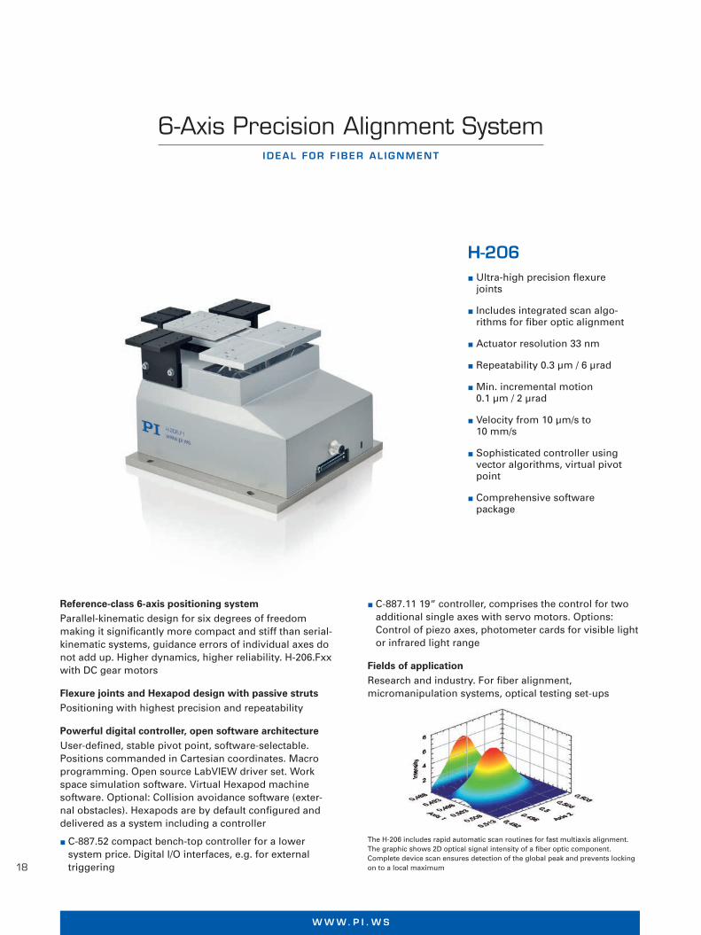
6-Axis Precision Alignment SystemIDEAL FOR F IBER AL IGNMENT
H-206 Ultra-high precision fl exure
joints
Includes integrated scan algo-rithms for fi ber optic alignment
Actuator resolution 33 nm
Repeatability 0 .3 µm / 6 µrad
Min . incremental motion 0 .1 µm / 2 µrad
Velocity from 10 µm/s to 10 mm/s
Sophisticated controller using vector algorithms, virtual pivot point
Comprehensive software package
Reference-class 6-axis positioning systemParallel-kinematic design for six degrees of freedom making it signifi cantly more compact and stiff than serial-kinematic systems, guidance errors of individual axes do not add up . Higher dynamics, higher reliability . H-206 .Fxx with DC gear motors
Flexure joints and Hexapod design with passive strutsPositioning with highest precision and repeatability
Powerful digital controller, open software architectureUser-defi ned, stable pivot point, software-selectable . Positions commanded in Cartesian coordinates . Macro programming . Open source LabVIEW driver set . Work space simulation software . Virtual Hexapod machine software . Optional: Collision avoidance software (exter-nal obstacles) . Hexapods are by default confi gured and delivered as a system including a controller
C-887 .52 compact bench-top controller for a lower system price . Digital I/O interfaces, e .g . for external triggering
The H-206 includes rapid automatic scan routines for fast multiaxis alignment . The graphic shows 2D optical signal intensity of a fi ber optic component . Complete device scan ensures detection of the global peak and prevents locking on to a local maximum ©
Phy
sik
Inst
rum
ente
(P
I) G
mb
H &
Co
. KG
201
5. S
ub
ject
to
ch
ang
e w
ith
ou
t n
oti
ce. L
ates
t re
leas
es a
vaila
ble
at
ww
w .p
i .ws .
R2
15/0
5/18
.0
C-887 .11 19“ controller, comprises the control for two additional single axes with servo motors . Options: Control of piezo axes, photometer cards for visible light or infrared light range
Fields of applicationResearch and industry . For fi ber alignment, micromanipulation systems, optical testing set-ups

19
P I | H E X A P O D SW W W . P I . W S
H-206.Fxx Unit Tolerance
Active axes X, Y, Z, θX, θY, θZ
Motion and positioning
Travel range* X -8 to 5 .7 mm
Travel range* Y ±5 .7 mm
Travel range* Z ±6 .7 mm
Travel range* θX ±5 .7 °
Travel range* θY ±6 .6 °
Travel range* θZ ±5 .5 °
Single-actuator design resolution 33 nm
Min . incremental motion X, Y, Z 0 .1 µm typ .
Min . incremental motion θX, θY, θZ 2 (0 .4“) µrad typ .
Repeatability X, Y, Z 0 .3 µm typ .
Repeatability θX, θY, θZ 6 µrad typ .
Velocity X, Y, Z 10 mm/s
Load (baseplate horizontal) 1 .5 kg max .
Miscellaneous
Operating temperature range 5 to 35 °C
Material Aluminum
Mass 5 .8 kg ±5%
Cable length 3 m ±10 mm
Technical data specifi ed at 20 ±3°C .Ask about custom designs!* The travel ranges of the individual coordinates (X, Y, Z, θX, θY, θZ) are interdependent . The data for each axis in this table shows its maximum travel, where all other axes
are at their zero positions . If the other linear or rotational coordinates are not zero, the available travel may be less .
The H-206 Hexapod shows extremely good repeatability of minute steps, in the above graph: 0 .5 µm steps with a load of 1 kg in X directionH-206, dimensions in mm ©
Phy
sik
Inst
rum
ente
(P
I) G
mb
H &
Co
. KG
201
5. S
ub
ject
to
ch
ang
e w
ith
ou
t n
oti
ce. L
ates
t re
leas
es a
vaila
ble
at
ww
w .p
i .ws .
R2
15/0
5/18
.0

20
W W W. P I . W SW W W . P I . W S
SpaceFABL O W - P R O F I L E S I X - A X I S M I C R O P O S I T I O N I N G S Y S T E M
SF-3000 BS Travel ranges linear
50 mm x 100 mm x 12 .7 mm
Travel ranges rotation Rx, Ry, Rz 10°
Load capacity 3 kg center mounted
Automatic alignment
Pivot point can be set by the customer
User friendly software
Can be used by any modern programming language
Including software, controller and amplifi ers
Vacuum Datasheet
©P
hysi
k In
stru
men
te (
PI)
Gm
bH
& C
o. K
G 2
015.
Su
bje
ct t
o c
han
ge
wit
ho
ut
no
tice
. Lat
est
rele
ases
ava
ilab
le a
t w
ww
.pi .w
s . 1
5/06
/10 .
0
Software Pivot point can be set by the customer Digital display of position and orientation Control by macro-language stored in own editor Jog mode
With one SpaceFAB SF-3000 BS all six degrees of freedom can be moved without additional positioning elements . The low weight of the moving platform allows high-dynamic positioning processes .The non preloaded design can easily carry up to 2 kg center mounted . SpaceFAB SF-3000 BS is operating in closed loop mode . SpaceFAB SF-3000 BS was especially developed for applications in fi ber-optic alignment . Furthermore SpaceFAB SF-3000 BS is perfectly designed
for auto alignment of optical components, micro-fabri-cation and bio-genetic . The core software used for the SpaceFAB . SF-3000 BS is the motion server . The motion server includes all the mathematical transformations so that the user can start movements directly by specifying the six coordinates x, y, z, Rx, Ry and Rz . It is also possible to move arbitrary trajectories in a contouring mode . The motion server can be used as a standalone software or in combination with or selfmade applications . These applications can be written in any modern programming language, the communication is done with TCP/IP . On request: A vacuum-version of the SpaceFAB SF-3000 BS is available in HV and UHV type Ask for: SpaceFAB SF-3000 BS Simulator . A program especially developed for simulation of travel range

21
P I | H E X A P O D SW W W . P I . W S
©P
hysi
k In
stru
men
te (
PI)
Gm
bH
& C
o. K
G 2
015.
Su
bje
ct t
o c
han
ge
wit
ho
ut
no
tice
. Lat
est
rele
ases
ava
ilab
le a
t w
ww
.pi .w
s . 1
5/06
/10 .
0
SF-3000 BS
Load Characteristics Fx (N) Fy (N) Fz (N) Mx (Nm) My (Nm) Mz (Nm)
DC-B-034 5 30 5 0 .2 0 .2 0 .2
Travel Range Linear X, Y, Z (mm)
50 x 100 x 12 .7 *
Rotation Rx, Ry, Rz (°)
10, 10, 10 *
Motor (Pitch 1 mm) DC-B-034
Speed max . X,Y, Z (mm/sec) 30
Speed max . Rx, Ry, Rz (°/sec) 10
Velocity Range (mm/sec) 0 .01 . . 30 **
Velocity Range (°/sec) 0 .001 . . 10 **
Weight (kg) 24
Bi-directional Repeatability LinearX, Y, Z (µm)
± 0 .5, ± 0 .5, ± 0 .5
RotationRx, Ry, Rz (°)
± 0 .0011
Resolution calc . without load LinearX, Y, Z (µm)
0 .2
RotationRx, Ry, Rz (°)
Depanding on the position of the pivot point
Resolution typical without load LinearX, Y, Z (µm)
0 .2
RotationRx, Ry, Rz (°)
0 .0005
Current (A) 2 .3
Voltage Range (V) 24
Stiffness, theoretical Kx, Ky, Kz (N/µm)
on request
Material Stainless steel, Aluminum black anodized

22
W W W. P I . W SW W W . P I . W S
©P
hysi
k In
stru
men
te (
PI)
Gm
bH
& C
o. K
G 2
016.
Su
bje
ct t
o c
han
ge
wit
ho
ut
no
tice
. Lat
est
rele
ases
ava
ilab
le a
t w
ww
.pi .w
s . 0
2/09
/16 .
0 R
2
High-Dynamics HexapodM A G N E T I C D I R E C T D R I V E F O R H I G H V E L O C I T Y
Reference-class 6-axis positioning systemParallel-kinematic design for six degrees of freedom making it signifi cantly more compact and stiffer than serialkinematic systems, no moved cables .Precise running of predefi ned motion profi les with high path accuracy: Sine curves and freely defi nable trajectories . Digital I/O interfaces for trigger signal emission
Powerful digital controller, open software architectureUser-defi ned, stable pivot point, software-selectable . Positions commanded in Cartesian coordinates . Macro programming . Open source LabVIEW driver set . Work space simulation software . Virtual Hexapod machine software . Optional: Collision avoidance software(external obstacles)
PIMag® voice coil magnetic drive for high velocity and high dynamicsNoncontact magnetic drive principle, no frictional or
rolling parts for guiding and joints . Zero-backlash positioning, no mechanical noise in the drivetrain . Silent . Low wear and high lifetime . Integrated linear encoder for reliable position control and repeatable accuracy . Fast and precise direction reversal through low moved mass and lightweight design (highly stiff, milled carbon parts)
H-860KMAG Dynamics to 25 Hz over 0 .1°
travel range
Integrated wave generator
Developed for test stations for image stabilization
Low moved mass
Velocity > 250 mm/s
Freely programmable, virtual pivot point
Fields of applicationResearch and industry, test systems, e .g ., for image stabilization in cameras and mobile devices . Equipment for camera test systems and image stabilization software, certifi cation according to CIPA planned . Oscillation simulation, eye tracking, simulation of human and artifi cial motion

23
P I | H E X A P O D SW W W . P I . W S
©P
hysi
k In
stru
men
te (
PI)
Gm
bH
& C
o. K
G 2
016.
Su
bje
ct t
o c
han
ge
wit
ho
ut
no
tice
. Lat
est
rele
ases
ava
ilab
le a
t w
ww
.pi .w
s . 0
2/09
/16 .
0 R
2
Preliminary Data H-860KMAG customized solution Unit Tolerance
Active axes X, Y, Z, θX, θY, θZ
Motion and positioning
Travel range X, Y, Z ±7 .5 mm
Travel range θX, θY, θZ ±4 °
Integrated sensor Linear encoder
Velocity X, Y, Z 250 mm/s max .
Linear acceleration 4 g
Load capacity 1 kg max .
Resonant frequency FX, FY, FZ 200 Hz
Drive properties
Actuator drive / motor type PIMag® voice coil
Motion and control
Servo characteristics 32-bit PID filter
Trajectory profile modes Sine, freely definable trajectories
Cycle time 1 ms
Processor CPU: ATOM Dual Core (1 .8 GHz)
Electrical properties
Max . output power 10- bit outputs for PWM drivers, 30 kHz
Max . output voltage TTL in PWM operation for SIGN and MAGN
Operating voltage 230 V typ .
Power consumption 600 W max .
Interface and operation
Communication interfaces TCP/ IP, RS-232USB (keyboard, mouse, manual control unit)
Command set PI General Command Set (GCS)
User software PIMikroMove
Software drivers LabVIEW drivers, dynamic libraries for Windows and Linux
Miscellaneous
Operating temperature range +5 to +40 °C
Hexapod mass 30 kg ±5 %
Cable length 3 m ±10 mm
Controller mass 2 .8 kg ±5 %
Technical data specified at 20 ±3 °C .* The travel ranges of the individual coordinates (X, Y, Z, θX, θY, θZ) are interdependent . The data for each axis in this table shows its maximum travel,
where all other axes are at their zero positions . If the other linear or rotational coordinates are not zero, the available travel may be less .Further information on www .pi .ws .
H-860KMAG, dimensions in mm

24
W W W. P I . W SW W W . P I . W S
6-Axis Miniature HexapodHIGH PREC IS ION IN A SMALL PACKAGE
H-810 Travel ranges to 40 mm / 60°
Load capacity to 5 kg
Actuator resolution 40 nm
Min . incremental motion to 0 .5 µm
Repeatability to ±0 .1 µm
Velocity to 2 .5 mm/s
Works in any orientation
Sophisticated controller using vector algorithms, virtual pivot point
Comprehensive software package
Reference-class 6-axis positioning systemParallel-kinematic design for six degrees of freedom making it signifi cantly more compact and stiff than serial-kinematic systems, higher dynamic range, no moved cables: Higher reliability, reduced friction
Direct drive with brushless DC motors (BLDC) and long-life ball screwsHigh precision, velocity and lifetime
Powerful digital controller, open software architectureUser-defi ned, stable pivot point, software-selectable . Positions commanded in Cartesian coordinates . Macro programming . Open source LabVIEW driver set . Work space simulation software . Virtual Hexapod machine software . Optional: Collision avoidance software (exter-nal obstacles) .
Hexapods are by default confi gured and delivered as a system including a controller
C-887 .52 compact bench-top controller for a lower system price . Digital I/O interfaces, e .g . for external triggering
C-887 .11 19“ controller, comprises the control for two additional single axes with servo motors . Options: Control of piezo axes, photometer cards for visible light or infrared light range
Fields of applicationResearch and industry . For micromanipulation, laser and optics alignment, biotechnology, tool control ©
Phy
sik
Inst
rum
ente
(P
I) G
mb
H &
Co
. KG
201
5. S
ub
ject
to
ch
ang
e w
ith
ou
t n
oti
ce. L
ates
t re
leas
es a
vaila
ble
at
ww
w .p
i .ws .
R1
15/0
5/19
.0

25
P I | H E X A P O D SW W W . P I . W S
H-810.Dxx Unit Tolerance
Active axes X, Y, Z, θX, θY, θZ
Motion and positioning
Travel range* X, Y ±20 mm
Travel range* Z ±6 .5 mm
Travel range* θX, θY ±10 °
Travel range* θZ ±30 °
Single-actuator design resolution 40 nm
Min . incremental motion X, Y 1 µm typ .
Min . incremental motion Z 0 .5 µm typ .
Min . incremental motion θX, θY, θZ 10 µrad typ .
Backlash X, Y 3 µm typ .
Backlash Z 0 .5 µm typ .
Backlash θX, θY 15 µrad typ .
Backlash θZ 75 µrad typ .
Repeatability X, Y ±1 µm typ .
Repeatability Z ±0 .1 µm typ .
Repeatability θX, θY ±3 µrad typ .
Repeatability θZ ±15 µrad typ .
Max . velocity X, Y, Z 2 .5 mm/s
Max . velocity θX, θY, θZ 60 mrad/s
Typ . velocity X, Y, Z 2 mm/s
Typ . velocity θX, θY, θZ 30 mrad/s
Mechanical properties
Stiffness X, Y 0 .1 N/µm
Stiffness Z 4 N/µm
Load (base plate horizontal / any orientation) 5 / 2 .5 kg max .
Holding force (base plate horizontal) 15 N max .
Motor type Brushless DC motor
Miscellaneous
Operating temperature range 0 to 50 °C
Material Stainless steel, aluminum
Mass 1 .7 kg ±5%
Cable length 2 m ±10 mm
Technical data specifi ed at 20 ±3°C .Ask about custom designs!* The travel ranges of the individual coordinates (X, Y, Z, θX, θY, θZ) are interdependent . The data for each axis in this table shows its maximum travel, where all other axes
are at their zero positions . If the other linear or rotational coordinates are not zero, the available travel may be less .
H-810, dimensions in mm ©P
hysi
k In
stru
men
te (
PI)
Gm
bH
& C
o. K
G 2
015.
Su
bje
ct t
o c
han
ge
wit
ho
ut
no
tice
. Lat
est
rele
ases
ava
ilab
le a
t w
ww
.pi .w
s . R
1 15
/05/
19 .0

26
W W W. P I . W SW W W . P I . W S
SpaceFAB
SF-6500 PS Linear travel ranges
13 mm x 13 mm x 10 mm
Rotatory travel ranges12° x 12° x 12°
Load capacity up to 2 kgcenter mounted
Pivot point can be set by the user
User friendly software
Can be used by any modernprogramming language
Including software, controller and amplifi ers
©P
hysi
k In
stru
men
te (
PI)
Gm
bH
& C
o. K
G 2
015.
Su
bje
ct t
o c
han
ge
wit
ho
ut
no
tice
. Lat
est
rele
ases
ava
ilab
le a
t w
ww
.pi .w
s . 1
5/06
/10 .
0
C O M PA C T, L O W - P R O F I L E S I X - A X I S M I C R O R O B O T

27
P I | H E X A P O D SW W W . P I . W S
SF-6500 PS
Travel range X, Y, Z (mm) 13 x 13 x 10
Travel range θx, θy, θz (°) 12 x 12 x 12
Speed max . (mm/s) 10
Speed max . (°/s) 5
Velocity range (mm/s) 0 .002 …10
Velocity range (°s) 0 .002 … 5
Bi-directional repeatability X,Y,Z (µm) (without load,center mounted directly on top of the platform)
±0 .008
Bi-directional repeatability θx, θy, θz (°) (without load,center mounted directly on top of the platform)
±0 .0005
Sensor resolution, without load X,Y,Z (µm) (without load,center mounted directly on top of the platform)
0 .005
Sensor resolution θx, θy, θz (°) (without load,center mounted directly on top of the platform)
Depending on the position of the pivot point
Sensor resolution typ ., without load X,Y,Z (µm) (without load,center mounted directly on top of the platform)
0 .005
Sensor resolution typ ., θx, θy, θz (°) (without load,center mounted directly on top of the platform)
Depending on the position of the pivot point
The maximum travel ranges in different coordinates directions ( X,Y,Z , θx, θy, θz ) are interdependent . The data for each axis in this table shows its maximum travel, wherec all other axes at their zero position . If the other linear or rotational coordinates are not zero, the available travel may be less . For more information, please contact us . The travel range is depending on the position of the pivot point .
©P
hysi
k In
stru
men
te (
PI)
Gm
bH
& C
o. K
G 2
015.
Su
bje
ct t
o c
han
ge
wit
ho
ut
no
tice
. Lat
est
rele
ases
ava
ilab
le a
t w
ww
.pi .w
s . 1
5/06
/10 .
0
SF-6500 PS, dimensions in mm

28
W W W. P I . W SW W W . P I . W S
Q-Motion SpaceFAB Micro RobotP I E Z O - M O T O R I Z E D I N E R T I A D R I V E , 1 N M S E N S O R R E S O L U T I O N
Q-845 Six-axis microrobotics system
Dimensions in reference position 175 mm × 165 mm × 77 mm
Linear travel ranges to 13 mm x 13 mm x 10 mm
Rotary travel ranges to 14° x 14° x 14°
Load capacity up to 5 N, center mounted
©P
hysi
k In
stru
men
te (
PI)
Gm
bH
& C
o. K
G 2
015.
Su
bje
ct t
o c
han
ge
wit
ho
ut
no
tice
. Lat
est
rele
ases
ava
ilab
le a
t w
ww
.pi .w
s . 1
5/06
/05 .
0
Preliminary Data Q-845 Unit Tolerance
Active axes X, Y, Z, θX, θY, θZ
Motion and Positioning
Travel range X, Y, Z ±6 .5, ±6 .5, ±5 mm
Travel range θX, θY, θZ ±7, ±7, ±7 °
Sensor resolution 1 nm
Bidirectional repeatability X, Y, Z ±0 .25 µm typ .
Bidirectional trajectory repeatability θX, θY, θZ ±17 .5 µrad typ .
Max . velocity X, Y, Z 10 mm/s
Max . velocity θX, θY, θZ 5 °/s
Mechanical Properties
Stiffness X, Y 0 .2 N/µm
Stiffness Z 3 .6 N/µm
Load (base plate horizontal) 5 N max .
Motor Type Piezoelectric inertia drive
Miscellaneous °C
Material Aluminum
Mass 1 .5 kg ±5 %
Cable length 2 m ±10 mm
29
P I | H E X A P O D SW W W . P I . W S
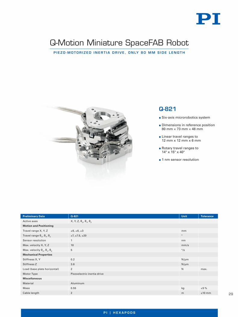
Q-Motion Miniature SpaceFAB RobotP I E Z O - M O T O R I Z E D I N E R T I A D R I V E , O N LY 8 0 M M S I D E L E N G T H
Q-821 Six-axis microrobotics system
Dimensions in reference position 80 mm × 73 mm × 48 mm
Linear travel ranges to 12 mm x 12 mm x 6 mm
Rotary travel ranges to 14° x 15° x 40°
1 nm sensor resolution
©P
hysi
k In
stru
men
te (
PI)
Gm
bH
& C
o. K
G 2
015.
Su
bje
ct t
o c
han
ge
wit
ho
ut
no
tice
. Lat
est
rele
ases
ava
ilab
le a
t w
ww
.pi .w
s . 1
5/06
/05 .
0
Preliminary Data Q-821 Unit Tolerance
Active axes X, Y, Z, θX, θY, θZ
Motion and Positioning
Travel range X, Y, Z ±6, ±6, ±3 mm
Travel range θX, θY, θZ ±7, ±7 .5, ±20 °
Sensor resolution 1 nm
Max . velocity X, Y, Z 10 mm/s
Max . velocity θX, θY, θZ 5 °/s
Mechanical Properties
Stiffness X, Y 0 .2 N/µm
Stiffness Z 3 .6 N/µm
Load (base plate horizontal) 2 N max .
Motor Type Piezoelectric inertia drive
Miscellaneous
Material Aluminum
Mass 0 .55 kg ±5 %
Cable length 2 m ±10 mm

30
W W W. P I . W SW W W . P I . W S
Fast 6-Axis HexapodF O R L O A D S T O 6 0 K G
H-900KSCO Low-wear, brushless DC motors
Travel ranges to 200 mm in X and Y and up to 170 mm in Z
Tilt and rotation angle to 66°
High velocities
H-9
00K
SC
O 0
9/20
16 0
.005
Su
bje
ct t
o c
han
ges
. © P
hys
ik In
stru
men
te (
PI)
Gm
bH
& C
o . K
G 2
016
R1
Reference-class 6-axis positioning systemParallel-kinematic design for six degrees of freedom making it signifi cantly more compact and stiff than serial-kinematic systems, higher dynamic range, no moved cables: Higher reliability, reduced friction .
Powerful digital controller, open software architectureOptional: Software for avoiding collisions in restricted workspace
Fields of applicationMotion simulation: Motion profi le compatible according to ISO 20672, ISO 8728, and ISO 16328 Industrial produc-tion, tool machines, automotive industry, shipping
Preliminary Data H-900KSCO customized solution Unit Tolerance
Motion and Positioning
Single-actuator design resolution 0 .58 µm
Travel range* X, Y 200 mm
Travel range* Z 170 mm
Travel range* θX, θY 66 °
Min . incremental motion X, Y 5 µm typ .
Backlash X, Y / Z 20 / 5 µm typ .
Backlash θX, θY / θZ50 / 90 µrad typ .
Repeatability X, Y / Z ±2 / ±0 .5 µm typ .
Repeatability θX, θY / θZ±5 / ±9 µrad typ .
Max . velocity X, Y Z 80 mm/s
Max . velocity θX, θY θZ 520 mrad/s
Typ . velocity X, Y, Z 20 mm/s
Typ . velocity θX, θY, θZ 130 mrad/s
Mechanical Properties
Load (base plate horizontal) 635 N max .
Holding force, de-energized (base plate horizontal)
635 N max .
Miscellaneous
Material Aluminum
Mass 65 .5 g
Technical data specifi ed at 20 ±3 °C .Ask about custom designs!* The travel ranges of the individual coordinates (X, Y, Z, θX, θY, θZ) are interdependent . The data for each axis in this table shows its maximum
travel, where all other axes are at their zero positions . If the other linear or rotational coordinates are not zero, the available travel may be less .

31
P I | H E X A P O D S
W W W . P I . W S
Unidirectional repeatability 5 µm
Load capacity to 75 kg
Clear aperture Ø 420 mm
Long Lifetime: 2 million cycles
Drive: brushless motors
Corresponds to protection class IP 64
Corrosion protection
M-850KWAH
The M-850KWAH custom hexapod for astronomy applications is protected by rubber boots and suitable materials . The special mechanical design as well as a non-standard controller make it particularly well-suited for telescope applications in the highlands of Chile, where it is operated outdoors at elevations up to 5,000 m above sea level
©P
hysi
k In
stru
men
te (
PI)
Gm
bH
& C
o. K
G 2
015.
Su
bje
ct t
o c
han
ge
wit
ho
ut
no
tice
. Lat
est
rele
ases
ava
ilab
le a
t w
ww
.pi .w
s . R
1 15
/05/
21 .0
Weather-Resistant Hexapod for AstronomyP R E C I S I O N 6 - A X I S P O S I T I O N E R F O R O U T D O O R A P P L I C AT I O N S
Customized solution Travel ranges Max. load Mass Dimensions
M-850KWAHWeather-Resistant Hexapod for Astronomy
X: ±10 mmY: ±11 mmZ: ±16 mm
75 kg 46 kg Ø external: 580 mmheight: 357 mm
W W W . P I . W S
UHV-Compatible Miniature Piezo HexapodH I G H - P R E C I S I O N P O S I T I O N I N G E V E N I N S T R O N G M A G N E T I C F I E L D S
Ultra-compact
UHV-compatible to 10-9 hPa
Nonmagnetic
Ultra-high precision fl exure joints
Load capacity to 1 .5 kg
Travel ranges to 1 .5 mm, to 2°
With NEXLINE® piezo stepping drives
P-911KNMV
The space-saving parallel-kinematic design allows for the low overall height of less than 90 mm and a diameter of only 100 mm . NEXLINE® piezo stepping motor drives and integrated incremental sensors ensure a position resolution down to 0 .1 µm in the linear axes
Customized solution Travel ranges Max. load Sensor resolution Dimensions
P-911KNMVMiniature Hexapod
X, Y, Z: 1 .5 mmθX, θY, θZ: 2°
1 .5 kg 0 .1 µm Ø external: 100 mmHeight: 90 mm
©P
hysi
k In
stru
men
te (
PI)
Gm
bH
& C
o. K
G 2
015.
Su
bje
ct t
o c
han
ge
wit
ho
ut
no
tice
. Lat
est
rele
ases
ava
ilab
le a
t w
ww
.pi .w
s . 1
5/05
/26 .
0

32
W W W. P I . W SW W W . P I . W S
Precision Hexapod for High LoadsVA C U U M - C O M PAT I B L E , P O S I T I O N I N G I N 6 A X E S W I T H M I C R O M E T E R A C C U R A C Y
Vacuum-compatible to 10-6 hPa
Six degrees of freedom
Load capacity to 1500 kg
Travel ranges to 340 mm / 60°
Min . incremental motion < 1 µm
Drive: brushless DC motors with gearhead
Sophisticated controller using vector algorithms
H-850KHLC
For positioning high loads in six axes of freedom, special requirements have to be fulfi lled by the positioning system . The H-850KHLC Hexapod aligns elements in vacuum environments with highest precision, the mechanical coupling is adapted to the vacuum chamber‘s characteristics
Customized solution Travel ranges Max. load Repeatability Dimensions
H-850KHLChigh-load Hexapod
X, Y: ±170 mmZ: ±100 mmθX, θY: ±20 °θZ: ±30 °
1500 kg ±3 µm Ø external: 1200 mmheight: 600 mm
©P
hysi
k In
stru
men
te (
PI)
Gm
bH
& C
o. K
G 2
015.
Su
bje
ct t
o c
han
ge
wit
ho
ut
no
tice
. Lat
est
rele
ases
ava
ilab
le a
t w
ww
.pi .w
s . R
1 15
/05/
21 .0
Customized solution
W W W . P I . W S
©P
hysi
k In
stru
men
te (
PI)
Gm
bH
& C
o. K
G 2
015.
Su
bje
ct t
o c
han
ge
wit
ho
ut
no
tice
. Lat
est
rele
ases
ava
ilab
le a
t w
ww
.pi .w
s . 1
5/05
/27 .
0
Piezo HexapodF I N E A D J U S T M E N T A N D A C T I V E , D Y N A M I C E R R O R C O R R E C T I O N
Highly dynamic reference-class 6-axis positioning systemParallel-kinematic design for six degrees of freedom making it signifi cantly more compact and stiff than serialkinematic systems, higher dynamic range, no moved cables: Higher reliability, reduced friction . Piezo actuator direct drives with high stiffness and resonant frequency for dynamic positioning . A powerful real-time digital controller controls the drive axes
Capacitive position sensors
Direct, absolute position measurement with subnanome-ter accuracy and a high bandwidth and stability
ApplicationsDynamic optimization of axial runout, eccentricity and evenness of rotation stages . Vibration insulation, fi ne adjustment
P-915KWEF Load capacity up to 1500 g
Min . incremental motion1 nm / 0 .07 µrad
Travel ranges to 70 µm
Capacitive sensors for dyna-mic scanning and precision positioning
33
P I | H E X A P O D S
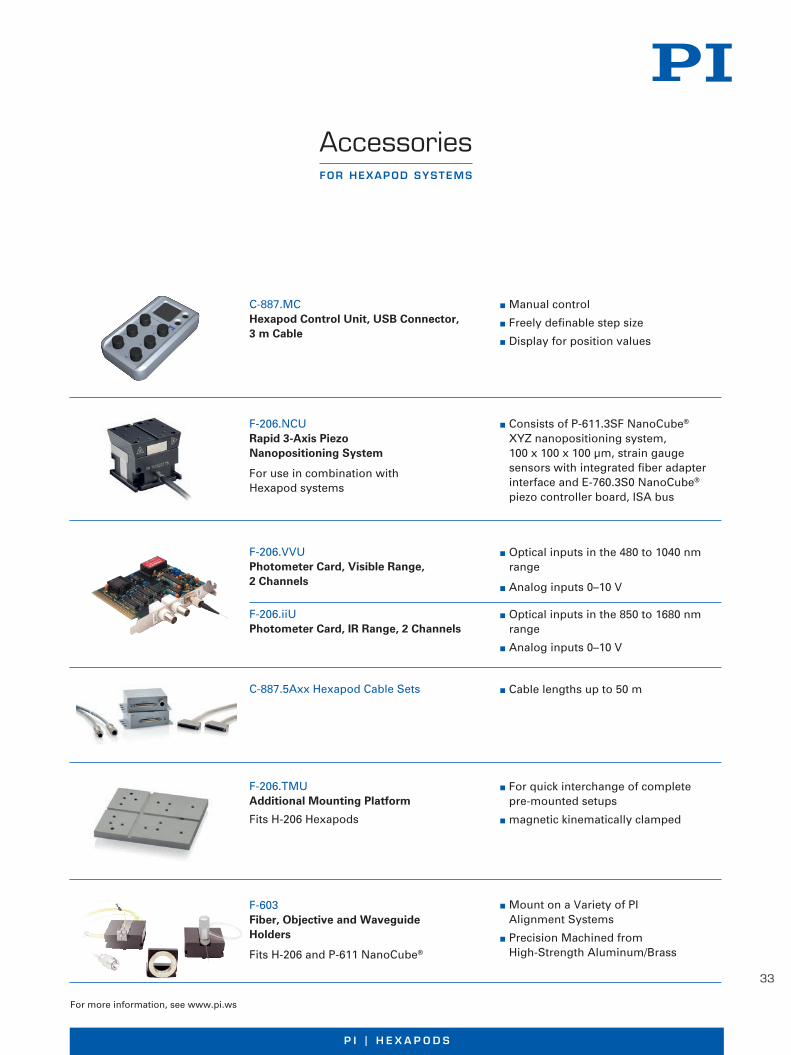
AccessoriesFOR HEXAPOD SYSTEMS
Consists of P-611 .3SF NanoCube® XYZ nanopositioning system, 100 x 100 x 100 µm, strain gauge sensors with integrated fiber adapter interface and E-760 .3S0 NanoCube® piezo controller board, ISA bus
F-206 .NCU Rapid 3-Axis Piezo Nanopositioning System
For use in combination with Hexapod systems
Cable lengths up to 50 m C-887 .5Axx Hexapod Cable Sets
For quick interchange of complete pre-mounted setups
magnetic kinematically clamped
F-206 .TMU Additional Mounting Platform
Fits H-206 Hexapods
For more information, see www .pi .ws
Manual control
Freely definable step size
Display for position values
C-887 .MC Hexapod Control Unit, USB Connector, 3 m Cable
Optical inputs in the 480 to 1040 nm range
Analog inputs 0–10 V
Optical inputs in the 850 to 1680 nm range
Analog inputs 0–10 V
F-206 .VVU Photometer Card, Visible Range, 2 Channels
F-206 .iiU Photometer Card, IR Range, 2 Channels
Mount on a Variety of PI Alignment Systems
Precision Machined from High-Strength Aluminum/Brass
F-603 Fiber, Objective and Waveguide Holders
Fits H-206 and P-611 NanoCube®

34
W W W. P I . W S
Controller for Hexapod Positioning SystemsC O M PA C T B E N C H -T O P D E V I C E F O R C O N T R O L L I N G 6 - A X I S S Y S T E M S
C-887.52x Sophisticated controller using
vector algorithms
Commanding in Cartesian coordinates
Coordinate systems can be switched with one simple command
Analog interfaces and Motion Stop
Extensive software support
Digital controller for 6-axis parallel kinematicsHigh-performance digital controller for Hexapods with DC motors . Additional control for two further single axes with integrated ActiveDrive .
FunctionsPosition input via Cartesian coordinates, coordinate transformation handled by the controller . To simplify integration of the Hexapod, the coordinate system can be quickly and easily changed . The real-time system prevents jitter and therefore guarantees constantly low response times . Stable, virtual pivot point can be defi ned freely . Data recorder for recording operating parame-ters such as motor control, velocity, position or position errors . Macro command language . An autostart macro allows stand-alone operation . The controller supports motor brakes and absolute-measuring sensors with BiSS interface .
Optional: Control via manual control unit
Collision checking for restricted space with PIVeriMove software
InterfacesEthernet for remote control and remote maintenance . RS-232 . USB connection for external input devices (HID) .
W W W . P I . W S
Additional interfaces (version-dependent): Motion Stop: The supply voltage of the hexapod drive
can be switched off using the external switch connected to the controller . The sensor technology remains active so that position information continues to be available and a reference move is not necessary when the drive is reactivated .
Analog inputs
Extensive softwarePIMikroMove user software . Common command set for all PI positioning systems . Dynamic libraries for Windows and Linux . Complete set of LabVIEW VI’s . Graphical user interfaces, confi guration software and graphically dis-played scan routines . Optional: PIVeriMove Software for checking a restricted operating space .
Also available:C-887 .53x Hexapod Motion Controller with EtherCAT Fieldbus InterfaceFurther information on www .pi .ws . ©
Ph
ysik
Inst
rum
ente
(P
I) G
mb
H &
Co
. KG
201
6 . S
ub
ject
to
ch
ang
e w
ith
ou
t n
oti
ce . L
ates
t re
leas
es a
vaila
ble
at
ww
w .p
i .ws .
16/
09/2
2 .0
R1

35
P I | H E X A P O D SW W W . P I . W S
©P
hys
ik In
stru
men
te (
PI)
Gm
bH
& C
o . K
G 2
016 .
Su
bje
ct t
o c
han
ge
wit
ho
ut
no
tice
. Lat
est
rele
ases
ava
ilab
le a
t w
ww
.pi .w
s . 1
6/09
/22 .
0 R
1
C-887.52C-887.521C-887.522C-887.523
Function 6-axis controller for Hexapods, incl . control of twoadditional single axesCompact benchtopExtending the functionality of C-887 .52:C-887 .521: Additional Analog InputsC-887 .522: Additional Motion StopC-887 .523: Additional Motion Stop and Analog Inputs
Drive type Servo motors (Hexapod and single axes)
Motion and control
Servo characteristics 32-bit PID controller
Trajectory profile modes Jerk-controlled generation of dynamics profilewith linear interpolation
Processor Intel Atom dual core (1 .8 GHz)
Servo cycle time 100 µs
Encoder input AB (quadrature) differential TTL signal, 50 MHz BiSS
Stall detection Servo off, triggered by position error
Reference point switch TTL
Electrical properties
Hexapod control 12-bit PWM signal, TTL, 24 kHz
Hexapod power source 24 V
Maximum output current 7 A
Interfaces and operation
Interface / communication TCP/IP, RS-232USB (HID, manual control unit)
Hexapod connection HD Sub-D 78-pin (f) for data transferM12 4-pin power input
Connectors for single axes Sub-D 15-pin (f)
I/O ports HD Sub-D 26-pin (f):4 × analog input (-10 to 10 V, via 12-bit A/D converter)4 × digital input (TTL)4 × digital output (TTL)
Analog inputs, only C-887 .521, C-887 .523 2 x BNC, -5 V to 5 V, via 16-bit A/D converter, 5 kHz bandwidth
Input for Motion Stop, only C-887 .521, C-887 .523
M12 8-pin (f)
Command set PI General Command Set (GCS)
User software PIMikroMove
Software drivers LabVIEW driver, dynamic libraries for Windowsand Linux
Manual operation Optional: C-887 .MC Manual control unit for Hexapods
Miscellaneous
Operating voltage 24 Vexternal power supply for 100 to 240 VAC,50 / 60 Hz, in the scope of delivery
Maximum current consumption 8 A
Operating temperature range 5 to 40 °C
Mass 2 .8 kg
Dimensions 280 (320) mm × 150 mm × 103 mmPower supply: 170 mm × 85 mm × 42 .5 mm

36
W W W. P I . W S
Key TechnologiesM O T I O N C O N T R O L O N S I X A X E S
P I | H E X A P O D S
37
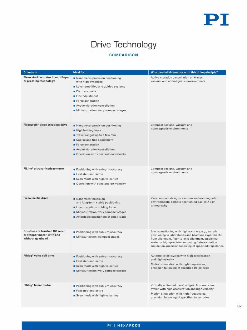
C O M PA R I S O N
Drive Technology
Drivetrain Ideal for … Why parallel kinematics with this drive principle?
Piezo stack actuator in multilayer or pressing technology
Nanometer-precision positioning with high dynamics
Lever-amplified and guided systems
Piezo scanners
Fine adjustment
Force generation
Active vibration cancellation
Miniaturization: very compact stages
Active vibration cancellation on 6 axes, vacuum and nonmagnetic environments
PiezoWalk® piezo stepping drive Nanometer-precision positioning
High holding force
Travel ranges up to a few mm
Coarse and fine adjustment
Force generation
Active vibration cancellation
Operation with constant low velocity
Compact designs, vacuum and nonmagnetic environments
PILine® ultrasonic piezomotor Positioning with sub-µm-accuracy
Fast step-and-settle
Scan mode with high velocities
Operation with constant low velocity
Compact designs, vacuum and nonmagnetic environments
Piezo inertia drive Nanometer-precision and long-term stable positioning
Low to medium holding force
Miniaturization: very compact stages
Affordable positioning of small loads
Very compact designs, vacuum and nonmagnetic environments, sample positioning e .g ., in X-ray tomography
Brushless or brushed DC servo or stepper motor, with and without gearhead
Positioning with sub-µm-accuracy
Miniaturization: compact stages
6-axis positioning with high accuracy, e .g ., sample positioning in laboratories and beamline experiments, fiber alignment, fiber-to-chip alignment, stable test systems, high-precision mounting fixtures motion simulation, precision following of specified trajectories
PIMag® voice coil drive Positioning with sub-µm-accuracy
Fast step-and-settle
Scan mode with high velocities
Miniaturization: very compact stages
Automatic test cycles with high acceleration and high velocity
Motion simulation with high frequencies, precision following of specified trajectories
PIMag® linear motor Positioning with sub-µm-accuracy
Fast step-and-settle
Scan mode with high velocities
Virtually unlimited travel ranges . Automatic test cycles with high acceleration and high velocity
Motion simulation with high frequencies, precision following of specified trajectories

38
W W W. P I . W SW W W . P I . W S
H I G H - P R E C I S I O N M O T I O N C O N T R O L I N U P T O S I X A X E S
Hexapods – Parallel-Kinematics Positioning Systems
Compact positioning system with 6 degrees of freedom
Hexapod platforms are used for precision positioning and alignment of loads in all six degrees of freedom, three linear axes, and three rotational axes .
Hexapods have a parallel-kinematics struc-ture, i .e ., the work piece is actuated simul-taneously by multiple actuators, rather than taking a stacked approach . The parallel ar-rangement of the actuators optimizes the overall system stiffness and allows for a lar-ge central aperture .
Precise positioning of loads from 2 kg to 2000 kg
Depending on their design, Hexapods can position loads from several kg up to seve-ral tons in any spatial orientation, in other words independently of the mounting ori-entation and with submicrometer precision .
Advantages over serial kinematics design
Hexapods can be designed considerably more compact than serially stacked multi-axis positioning systems and there are no moving cables to increase the footprint . Since only a single lightweight platform is actuated the moving mass is signifi cantly smaller, too . This results in improved dyna-mics with considerably faster response and reduced step-and-settle times . Furthermore, there are no cable management issues as with serial-kinematics multi-axis positio-ners . Here friction and torque caused by the cables reduce the positioning accuracy and repeatability .
This principle where the lowest axis not only moves the mass of the payload but also the mass all other positioning mechanics above reduces the stiffness and dynamic perfor-mance and results in the accumulation of individual off-axis errors .
Large central aperture
Three linear axes, three rotational axes
Low moving mass, low inertia
Excellent dynamic beha-vior, fast step-and-settle
Small installation space
High stiffness
Freely defi nable pivot point
Minimized axis crosstalk motion
Very good repeatability
pi_120265_titel_6achsen.indd 1 16.05.12 16:05
© P
hys
ik In
stru
men
te (
PI)
Gm
bH
& C
o . K
G 2
012 .
Su
bje
ct t
o c
han
ge
wit
ho
ut
no
tice
. Lat
est
rele
ases
ava
ilab
le a
t w
ww
.pi .w
s . 1
2/05
/29 .
0
W W W . P I . W S
H I G H - P R E C I S I O N M O T I O N C O N T R O L I N U P T O S I X A X E S
Hexapods – Parallel-Kinematics Positioning Systems
Compact positioning system with 6 degrees of freedom
Hexapod platforms are used for precision positioning and alignment of loads in all six degrees of freedom, three linear axes, and three rotational axes .
Hexapods have a parallel-kinematics struc-ture, i .e ., the work piece is actuated simul-taneously by multiple actuators, rather than taking a stacked approach . The parallel ar-rangement of the actuators optimizes the overall system stiffness and allows for a lar-ge central aperture .
Precise positioning of loads from 2 kg to 2000 kg
Depending on their design, Hexapods can position loads from several kg up to seve-ral tons in any spatial orientation, in other words independently of the mounting ori-entation and with submicrometer precision .
Advantages over serial kinematics design
Hexapods can be designed considerably more compact than serially stacked multi-axis positioning systems and there are no moving cables to increase the footprint . Since only a single lightweight platform is actuated the moving mass is signifi cantly smaller, too . This results in improved dyna-mics with considerably faster response and reduced step-and-settle times . Furthermore, there are no cable management issues as with serial-kinematics multi-axis positio-ners . Here friction and torque caused by the cables reduce the positioning accuracy and repeatability .
This principle where the lowest axis not only moves the mass of the payload but also the mass all other positioning mechanics above reduces the stiffness and dynamic perfor-mance and results in the accumulation of individual off-axis errors .
Large central aperture
Three linear axes, three rotational axes
Low moving mass, low inertia
Excellent dynamic beha-vior, fast step-and-settle
Small installation space
High stiffness
Freely defi nable pivot point
Minimized axis crosstalk motion
Very good repeatability
pi_120265_titel_6achsen.indd 1 16.05.12 16:05
© P
hys
ik In
stru
men
te (
PI)
Gm
bH
& C
o . K
G 2
012 .
Su
bje
ct t
o c
han
ge
wit
ho
ut
no
tice
. Lat
est
rele
ases
ava
ilab
le a
t w
ww
.pi .w
s . 1
2/05
/29 .
0

39
P I | H E X A P O D SW W W . P I . W S
Selection of the mechanical components
A Hexapod is more than the sum of its indi-vidual parts . All components have to be ca-refully selected and designed with the idea of multi-axis motion in mind . This starts with the use of backlash-free mechanical parts and thermally matched materials . The joints also play a very important part be-cause there are 12 of them and all are in-volved in every move the Hexapod makes . The precision of every strut (actuator) itself is important, too, however it is not enough to equip these actuators with high-resoluti-on sensors and hope the Hexapod system accuracy will be identical to the sensor reso-lution . On the contrary, there are other more important factors .
Motors and drives
PI Hexapods are based on electromechani-cal or piezoelectric drives and differ signifi -cantly from the hydraulic Hexapods known from fl ight or driving simulators . Depen-ding on the application, direct-drive designs or gear motors are used, rollerscrews or ballscrews, brushless motors and even line-ar motors are employed . PI also makes non-magnetic and EUV compatible Hexapods .
Joints
A number of different joint designs is also available to optimize the Hexapods . If high load capacity and overall stiffness are im-portant universal joints with two ortho-gonally arranged axes, i .e . two degrees of freedom, are the premium choice .
Ball and socket joints offer more degrees of freedom in a relatively simple design . How-ever, the overall stiffness and precision in case of external loads and torque can suffer . A compensating preload is recommended
but requires drives with high output forces such as the NEXLINE® piezo walk motors shown in the fi gure here .
If the highest precision is required, fl exure joints are recommended . They exhibit neit-her friction nor backlash and do not require lubricants . However, they only work over re-latively small travel ranges .
The work space
In addition to linear motion, the Hexapod platform can carry out any combination of tilting and rotation around a freely selectab-le pivot point . Due to the parallel kinematics design, the work space is also not limited by cables movement and cable management systems .
Universal joints of the H-840 Hexapod model
If the stiffness requirements of the total system are lower, a 3-strut design can also be used in which additional degrees of freedom are produced because a passive strut can be moved in two or more axes . Example: In the SpaceFAB the individual struts are driven by one XY translation stage each (fi gure: PI miCos GmbH)
Ball and socket joints
The Z-axis positioning accuracy of an H-824 Hexapod over 25 mm full travel is in the range of a few micro-meters only, with the repeatability well below ±0 .1 µm

40
W W W. P I . W SW W W . P I . W S
Hexapods with passive struts
IInstead of variable, active struts, Hexapo-ds can be designed with passive struts that show constant strut length . In this case the coupling points or joints are usually moved along a linear path . This design is advanta-geous when the drive unit is to be separated from the platform, e .g ., outside of vacuum chambers .
Advanced motion control
The individual drives of a Hexapod do not necessarily point in the direction of motion, which is why a powerful controller that can handle the required coordinate transforma-tions in real time is needed .
PI uses advanced digital controllers along with user-friendly software . All motion commands are specifi ed in Cartesian coor-dinates, and all transformations to the indi-vidual actuators take place inside the con-troller .
An important Hexapod property is the free-ly defi nable pivot point . The possibility to rotate around any point in space opens up new applications from fi ber alignment to astronomy .
The entirety of all combinations of translations and rotations that a Hexapod can approach from any given position is called the work space; it is given in reference to the origin of the coordinate system used . The work space can be limited by external factors such as obstacles or the position and size of the load
Constant strut-length Hexapod design . The drive units move the joint position up and down affecting the linear and rotary position of the platform

41
P I | H E X A P O D S
Standardized fieldbus interfaces make integration easier: Hexapods in automation technology
Precise trajectory control using G-Code
The Hexapod controller may also control the trajectory based on G-Code according to DIN 66025/ISO 6983 . The G-Code command language is directly implemented in the controller .
With G-Code, moving along complex trajec-tories with defined velocity and acceleration is possible . The Hexapod system can, for exam ple, move a workpiece or tool jerk-controlled and with high precision during machining with out the mechanical system starting to vibrate .
User-defined coordinate systems
To adapt the trajectory perfectly to the re-quirements of the application, it is possible to de fine various coordinate systems which refer, for example, to the position of work- piece or tool . This offers great advantages for applications in industrial automation, but also for fiber alignment .
Standardized automation interfaces
Standardized fieldbus interfaces guarantee an easy connection to parent PLC or CNC controls so that Hexapods can work syn-chronously with other components in one automation line.
The PLC acts as master and defines the tar-get position in Cartesian coordinates and the trajectories; in return, it gets the actual positions also over the fieldbus interface. All other calculations required to command the parallel-kinematic six-axis system are done by the Hexapod controller, i.e. transforming the nominal posi tions from Cartesian coor-
dinates into drive commands for the indivi-dual drives. In this case, the controller acts just like an intelligent drive.
The cycle times for determining new posi-tions, evaluating signals and synchronizing are between 1 and 3 ms. Fieldbus inter-faces are currently available for Profibus, EtherCAT, Profinet, CANopen and SERCOS.
C O N T R O L A N D I N T E R FA C E S F O R E A S Y I N T E G R AT I O N
Hexapods in Automation
PI Hexapod Controller
Fieldbus Slave Interface
Motor Controller with Speed/Rotation Angle Control
Fine Inter-polation
Calculation of Inverse Kinematics
Transformation of Encoder Values to Cartesian Coordinates
Cartesian Nominal Position
PLC/CNC
(Fieldbus Master)
Cartesian Actual Position
PI Hexapod
Block diagram: The Hexapod controller acts just like an intelligent drive. The fieldbus interface can be exchanged to allow communication with numerous types of PLC or CNC control
Any coordinate system used as a reference for target values of the Hexapod may be defined

42
W W W. P I . W S
Direct magnetic drives for high accelerations
High motion repeatability in the submicrometer range
Running of predefined motion profiles
Operating frequencies of >100 Hz for small strokes
Dynamic Motion and Scanning in Six Axes
Motion simulators have higher motion dy-namics requirements (shakers) . They re-peatedly perform defined motion cycles, for example for quality assurance and function monitoring of products in mobile use . Mo-tions that are generated, for example, by trembling hands or a moving car, are simu-lated by means of sine curves and freely de-finable trajectories .
Six degrees of freedom allow fast motion sequences to be repeated identically in dif-ferent locations of the workspace .
Applications
Testing of image stabilization algorithms in camera systems, also for mobile devices. In the process, the Camera & Imaging Pro-ducts Association (CIPA) Standards must be taken into account.
Simulation of oscillations, e.g. eye motion simulation and eye tracking in the medical field.
Drive Principles
To generate highly dynamic motions, va-rious drive principles can be used. Hexa-pods with electromagnetic, brushless tor-que motors and an appropriate mechanical design of the drive train and sensor sys- tem can already provide velocities of up to 25 mm/s and accelerations of up to 2 g.
The best dynamic performance is achieved by Hexapods with magnetic PIMag® di-rect drives; they offer velocities of several hundred mm/s and accelerations of up to 4 g. The special design which includes flex-ure joints completely dispenses with rolling or frictional elements, thus allowing a zero-backlash motion without mechanical noise.
T E S T E Q U I P M E N T W I T H S I X M O T I O N A X E S F O R L A B O R AT O R Y A N D I N D U S T R I A L U S E
High-Dynamics Hexapod as Motion Simulator
PI Hexapod in a test setup for CIPA certification (Image: Image Engineering)
CIPA
図記号分科会
2003/02/10CIPA LOGO SOURCE DATA mono/full/uni color
●小サイズ用●ユニカラー●横組み
●縦組み1(組織名称英文)
●縦組み2(法人組織名称英和文)
●縦組み3(組織名称英文/大)
●縦組み4(法人組織名称英和文/大)
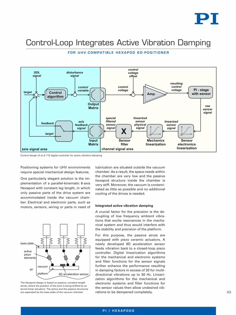
43
P I | H E X A P O D Sw w w . p i . w s
F o r U H V - C o m pat i b l e H e x a p o d 6 d - p o s i t i o n e r
Control-Loop Integrates Active Vibration Damping
Positioning systems for UHV environments require special mechanical design features.
One particularly elegant solution is the im-plementation of a parallel-kinematic 6-axis Hexapod with constant leg length, in which only passive parts of the drive system are accommodated inside the vacuum cham-ber. Electrical and electronic parts, such as motors, sensors, wiring or parts in need of
lubrication are situated outside the vacuum chamber. As a result, the space needs within the chamber are very low and the passive hexapod structure inside the chamber is very stiff. Moreover, the vacuum is contami-nated as little as possible and no additional cooling of the drives is needed.
Integrated active vibration damping
A crucial factor for the precision is the de-coupling of low frequency ambient vibra-tions that excite resonances in the mecha-nical system and thus would interfere with the stability and precision of the platform.
For this purpose, the passive struts are equipped with piezo ceramic actuators. A newly developed 6D acceleration sensor feeds vibration back to a closed-loop piezo controller. Digital linearization algorithms for the mechanical and electronic systems and filter functions for the sensor signals further enhance the performance resulting in damping factors in excess of 20 for multi-directional vibrations up to 50 Hz. Lineari-zation algorithms for the mechanical and electronic systems and filter functions for the sensor values then allow undesired vib-rations to be dampened completely. ©
Ph
ysik
Inst
rum
ente
(P
I) G
mb
H &
Co
. KG
201
2. S
ub
ject
to
ch
ang
e w
ith
ou
t n
oti
ce. L
ates
t re
leas
es a
vaila
ble
at
ww
w.p
i.ws.
12/
06/0
4.0
Control design of an E-712 digital controller for active vibration damping
The Hexapod design is based on passive, constant-length struts, where the position of the joint is being shifted by ex-ternal linear actuators. The active and the passive structures are separated by the base plate of the vacuum chamber
w w w . p i . w s
F o r U H V - C o m pat i b l e H e x a p o d 6 d - p o s i t i o n e r
Control-Loop Integrates Active Vibration Damping
Positioning systems for UHV environments require special mechanical design features.
One particularly elegant solution is the im-plementation of a parallel-kinematic 6-axis Hexapod with constant leg length, in which only passive parts of the drive system are accommodated inside the vacuum cham-ber. Electrical and electronic parts, such as motors, sensors, wiring or parts in need of
lubrication are situated outside the vacuum chamber. As a result, the space needs within the chamber are very low and the passive hexapod structure inside the chamber is very stiff. Moreover, the vacuum is contami-nated as little as possible and no additional cooling of the drives is needed.
Integrated active vibration damping
A crucial factor for the precision is the de-coupling of low frequency ambient vibra-tions that excite resonances in the mecha-nical system and thus would interfere with the stability and precision of the platform.
For this purpose, the passive struts are equipped with piezo ceramic actuators. A newly developed 6D acceleration sensor feeds vibration back to a closed-loop piezo controller. Digital linearization algorithms for the mechanical and electronic systems and filter functions for the sensor signals further enhance the performance resulting in damping factors in excess of 20 for multi-directional vibrations up to 50 Hz. Lineari-zation algorithms for the mechanical and electronic systems and filter functions for the sensor values then allow undesired vib-rations to be dampened completely. ©
Ph
ysik
Inst
rum
ente
(P
I) G
mb
H &
Co
. KG
201
2. S
ub
ject
to
ch
ang
e w
ith
ou
t n
oti
ce. L
ates
t re
leas
es a
vaila
ble
at
ww
w.p
i.ws.
12/
06/0
4.0
Control design of an E-712 digital controller for active vibration damping
The Hexapod design is based on passive, constant-length struts, where the position of the joint is being shifted by ex-ternal linear actuators. The active and the passive structures are separated by the base plate of the vacuum chamber

44
W W W. P I . W SW W W . P I . W S
E F F E C T I V E A N D C O M F O R TA B L E S O L U T I O N S
Motion Control Software from PI
All digital controllers made by PI are accom-panied by a comprehensive software packa-ge . PI supports users as well as program-mers with detailed online help and manuals which ease initiation of the inexperienced but still answer the detailed questions of the professional . Updated software and drivers are always available to PI customers free of charge via the Internet .
PI software covers all aspects of the appli-cation* from the easy start-up to convenient system operation via a graphical interface and quick and comprehensive integration in customer written application programs .
Universal command set simplifi es commissioning and programming
PI’s General Command Set (GCS) structure is consistent for all controllers regardless of
their complexity and purpose . GCS with its many preprogrammed functions accelera-tes the orientation phase and the application development process signifi cantly while reducing the chance of errors, because the commands for all supported devices are identical in syntax and function . Further advantages are that different PI controllers can be added and integrated more easily and system upgrades can be introduced with a minimum of programming effort .
Supported operating systems
Windows XP (SP3)
Windows VISTA
Windows 7 32/64 bit
Linux 32/64 bit
NanopositioningS U B - N A N O M E T E R R E S O L U T I O N
MicropositioningL O N G T R A V E L R A N G E S
Parallel KinematicsU P T O 6 D E G R E E S O F F R E E D O M
Drive TechnologyD C , S T E P P E R , P I E Z O , M A G N E T I C
GCSM O T I O N C O N T R O L
Ph
ysik
Inst
rum
ente
(P
I) G
mb
H &
Co
. KG
201
2 . S
ub
ject
to
ch
ang
e w
ith
ou
t n
oti
ce . L
ates
t re
leas
es a
vaila
ble
at
ww
w .p
i .ws .
12/
05/2
3 .0
* Not every function is available for all controllers . For details, please refer to the corresponding product data sheets .
W W W . P I . W S
E F F E C T I V E A N D C O M F O R TA B L E S O L U T I O N S
Motion Control Software from PI
All digital controllers made by PI are accom-panied by a comprehensive software packa-ge . PI supports users as well as program-mers with detailed online help and manuals which ease initiation of the inexperienced but still answer the detailed questions of the professional . Updated software and drivers are always available to PI customers free of charge via the Internet .
PI software covers all aspects of the appli-cation* from the easy start-up to convenient system operation via a graphical interface and quick and comprehensive integration in customer written application programs .
Universal command set simplifi es commissioning and programming
PI’s General Command Set (GCS) structure is consistent for all controllers regardless of
their complexity and purpose . GCS with its many preprogrammed functions accelera-tes the orientation phase and the application development process signifi cantly while reducing the chance of errors, because the commands for all supported devices are identical in syntax and function . Further advantages are that different PI controllers can be added and integrated more easily and system upgrades can be introduced with a minimum of programming effort .
Supported operating systems
Windows XP (SP3)
Windows VISTA
Windows 7 32/64 bit
Linux 32/64 bit
NanopositioningS U B - N A N O M E T E R R E S O L U T I O N
MicropositioningL O N G T R A V E L R A N G E S
Parallel KinematicsU P T O 6 D E G R E E S O F F R E E D O M
Drive TechnologyD C , S T E P P E R , P I E Z O , M A G N E T I C
GCSM O T I O N C O N T R O L
Ph
ysik
Inst
rum
ente
(P
I) G
mb
H &
Co
. KG
201
2 . S
ub
ject
to
ch
ang
e w
ith
ou
t n
oti
ce . L
ates
t re
leas
es a
vaila
ble
at
ww
w .p
i .ws .
12/
05/2
3 .0
* Not every function is available for all controllers . For details, please refer to the corresponding product data sheets .

P I | H E X A P O D S
45
W W W . P I . W S
PIMikroMove software ensures rapid start-up
PIMikroMove is PI’s convenient graphi-cal user interface for any type of digital controller and positioning system, regard-less of whether piezoelectric, linear motors, or classical electrical motor drives are used and independent of the confi guration and number of axes .
All connected controllers and axes are displayed and controlled consistently with the same graphical interface . Two or more independent axes can be controlled by the position pad using a mouse or joystick; Hexapod six-axis positioning systems are also displayed graphically .
Macro programs simplify repetitive tasks for example in automated processes . The mac-ros are created as GCS command sets that can be executed directly on the controller, e .g ., as a start-up macro that allows stand-alone operation; they can also be processed by the host PC .
Scan and align algorithms can record ana-log values, e .g ., the output of a power meter as a function of position for later evaluation with external software . They can also auto-matically fi nd the global maximum of, for example, the coupling effi ciency of optical devices .
Depending on the specifi c controller, PIMikroMove supports a number of additi-onal functions . A data recorder can record system parameters and other variables during motion for later analysis .
Optimizing system behavior
When the mechanical properties of a positi-oning system are changed, e .g ., by applying a different load, motion control parameters often need to be adapted . PI software provi-des tools for optimization of the system res-ponse and stability . Different parameter sets can be saved for later recall, also accessible from custom application programs .

46
W W W. P I . W SW W W . P I . W S
R A P I D I N T E G R AT I O N O F P I P O S I T I O N I N G S Y S T E M S A N D C O N T R O L L E R S
Programming
In measuring and control technology and automation engineering, many applications are produced in LabVIEW . PI provides com-plete LabVIEW drivers sets to facilitate pro-gramming . A controller-specifi c Confi gurati-on_Setup VI is integrated at the start of the LabVIEW application and includes all system information and initiation steps required for start-up . The application itself is implemented with controller-independent VIs . In case of a controller change or upgrade, it is usually only necessary to exchange the Confi gurati-on_Setup VI , whereas the application-specifi c code remains identical due to the consistent GCS command set structure . The driver set includes many specifi c exemplary programs, e .g ., comprehensive scan and align applica-
tions that can be used as template for own programs . Moreover, the open source code of many VIs allows for rapid adaptation to the user needs .
Flexible integration in text-based programming languages
The integration of PI positioning systems in text-based programming languages under Microsoft Windows or Linux is simplifi ed by program libraries and exemplary codes .
These libraries support all common pro-gramming languages and all PI positioning systems , allowing the PI GCS command set functions to be integrated seamlessly in ex-ternal programs .
Third-party software packages
Drivers for the PI GCS commands have now been integrated in many third-party soft-ware packages . This allows for the seamless integration of PI positioning systems in soft-ware suites such as MetaMorph, µManager, MATLAB, and ScanImage . Moreover, EPICS and TANGO drivers are available for integra-tion into experiments of large-scale research facilities . The drivers for µManager, MATLAB and a large part of the EPICS drivers are being developed and serviced in-house by PI .
Supported languages and software environments
C, C++, Python, Visual C++, Visual Basic, Delphi
LabVIEW, MATLAB, µManager, EPICS, TANGO, MetaMorph
and all programming environments that support the loading of DLLs
W W W . P I . W S
R A P I D I N T E G R AT I O N O F P I P O S I T I O N I N G S Y S T E M S A N D C O N T R O L L E R S
Programming
In measuring and control technology and automation engineering, many applications are produced in LabVIEW . PI provides com-plete LabVIEW drivers sets to facilitate pro-gramming . A controller-specifi c Confi gurati-on_Setup VI is integrated at the start of the LabVIEW application and includes all system information and initiation steps required for start-up . The application itself is implemented with controller-independent VIs . In case of a controller change or upgrade, it is usually only necessary to exchange the Confi gurati-on_Setup VI , whereas the application-specifi c code remains identical due to the consistent GCS command set structure . The driver set includes many specifi c exemplary programs, e .g ., comprehensive scan and align applica-
tions that can be used as template for own programs . Moreover, the open source code of many VIs allows for rapid adaptation to the user needs .
Flexible integration in text-based programming languages
The integration of PI positioning systems in text-based programming languages under Microsoft Windows or Linux is simplifi ed by program libraries and exemplary codes .
These libraries support all common pro-gramming languages and all PI positioning systems , allowing the PI GCS command set functions to be integrated seamlessly in ex-ternal programs .
Third-party software packages
Drivers for the PI GCS commands have now been integrated in many third-party soft-ware packages . This allows for the seamless integration of PI positioning systems in soft-ware suites such as MetaMorph, µManager, MATLAB, and ScanImage . Moreover, EPICS and TANGO drivers are available for integra-tion into experiments of large-scale research facilities . The drivers for µManager, MATLAB and a large part of the EPICS drivers are being developed and serviced in-house by PI .
Supported languages and software environments
C, C++, Python, Visual C++, Visual Basic, Delphi
LabVIEW, MATLAB, µManager, EPICS, TANGO, MetaMorph
and all programming environments that support the loading of DLLs

47
P I | H E X A P O D SW W W . P I . W S
R A P I D I N T E G R AT I O N O F P I P O S I T I O N I N G S Y S T E M S A N D C O N T R O L L E R S
Programming
In measuring and control technology and automation engineering, many applications are produced in LabVIEW . PI provides com-plete LabVIEW drivers sets to facilitate pro-gramming . A controller-specifi c Confi gurati-on_Setup VI is integrated at the start of the LabVIEW application and includes all system information and initiation steps required for start-up . The application itself is implemented with controller-independent VIs . In case of a controller change or upgrade, it is usually only necessary to exchange the Confi gurati-on_Setup VI , whereas the application-specifi c code remains identical due to the consistent GCS command set structure . The driver set includes many specifi c exemplary programs, e .g ., comprehensive scan and align applica-
tions that can be used as template for own programs . Moreover, the open source code of many VIs allows for rapid adaptation to the user needs .
Flexible integration in text-based programming languages
The integration of PI positioning systems in text-based programming languages under Microsoft Windows or Linux is simplifi ed by program libraries and exemplary codes .
These libraries support all common pro-gramming languages and all PI positioning systems , allowing the PI GCS command set functions to be integrated seamlessly in ex-ternal programs .
Third-party software packages
Drivers for the PI GCS commands have now been integrated in many third-party soft-ware packages . This allows for the seamless integration of PI positioning systems in soft-ware suites such as MetaMorph, µManager, MATLAB, and ScanImage . Moreover, EPICS and TANGO drivers are available for integra-tion into experiments of large-scale research facilities . The drivers for µManager, MATLAB and a large part of the EPICS drivers are being developed and serviced in-house by PI .
Supported languages and software environments
C, C++, Python, Visual C++, Visual Basic, Delphi
LabVIEW, MATLAB, µManager, EPICS, TANGO, MetaMorph
and all programming environments that support the loading of DLLs
W W W . P I . W S
R A P I D I N T E G R AT I O N O F P I P O S I T I O N I N G S Y S T E M S A N D C O N T R O L L E R S
Programming
In measuring and control technology and automation engineering, many applications are produced in LabVIEW . PI provides com-plete LabVIEW drivers sets to facilitate pro-gramming . A controller-specifi c Confi gurati-on_Setup VI is integrated at the start of the LabVIEW application and includes all system information and initiation steps required for start-up . The application itself is implemented with controller-independent VIs . In case of a controller change or upgrade, it is usually only necessary to exchange the Confi gurati-on_Setup VI , whereas the application-specifi c code remains identical due to the consistent GCS command set structure . The driver set includes many specifi c exemplary programs, e .g ., comprehensive scan and align applica-
tions that can be used as template for own programs . Moreover, the open source code of many VIs allows for rapid adaptation to the user needs .
Flexible integration in text-based programming languages
The integration of PI positioning systems in text-based programming languages under Microsoft Windows or Linux is simplifi ed by program libraries and exemplary codes .
These libraries support all common pro-gramming languages and all PI positioning systems , allowing the PI GCS command set functions to be integrated seamlessly in ex-ternal programs .
Third-party software packages
Drivers for the PI GCS commands have now been integrated in many third-party soft-ware packages . This allows for the seamless integration of PI positioning systems in soft-ware suites such as MetaMorph, µManager, MATLAB, and ScanImage . Moreover, EPICS and TANGO drivers are available for integra-tion into experiments of large-scale research facilities . The drivers for µManager, MATLAB and a large part of the EPICS drivers are being developed and serviced in-house by PI .
Supported languages and software environments
C, C++, Python, Visual C++, Visual Basic, Delphi
LabVIEW, MATLAB, µManager, EPICS, TANGO, MetaMorph
and all programming environments that support the loading of DLLs
W W W . P I . W S
Hexapod-Specifi c Software
Due to their parallel kinematic structure, Hexapods necessitate a particularly complex control system . The position coordinates, for example, are given in virtu-al Cartesian axes which are then converted into positioning commands for the indivi-dual actuators by the controller . PI supplies special software that allow the 6-axes posi-tioners to be more convenient in operation and easier to integrate .
Determining the work space
The limits of the work space vary depen-ding on the current position of the Hexa-pod (translation and rotation coordinates) and the current coordinates of the pivot point . A special software tool included with each PI Hexapod calculates these limits and displays them graphically .
Checking the permissible load
As with any multiaxis positioning system, the load limit of the Hexapod varies as a function of a number of factors such as orientation of the Hexapod, size and position of the payload, current position
(translation and rotation coordinates) of the Hexapod platform, and forces and moments acting on the platform .
The Hexapod software package includes a PI simulation tool that calculates all forces and moments and compares them individu-ally against the specifi ed load limits of the corresponding Hexapod mechanics .
Preventing collisions with PIVeriMove
Another proprietary PI simulation software tool enables offl ine graphical confi guration and simulation of the Hexapod motion in the application environment . CAD data of objects can be imported or approximated with simple shapes such as cylinders and cuboids . PIVeriMove then checks restric-tions in the work space . Implemented in the controller fi rmware or the application software, this prevents the Hexapod from approaching positions where the platform, struts, or the mounted load would collide with the surroundings .
Emulation: The Hexapod system as a virtual machine
A virtual machine that can be installed on the customer’s host PC is available to emulate a complete Hexapod systems (mechanics, controller and even periphe-rals) . Application programs can then be developed and pre-tested, different load scenarios can be simulated and the work space can be determined before the system arrives, saving signifi cant cost and develop-ment time .
HexaApp: PI Hexapod control via iPhone, iPad or iPod
The Hexapod system can also be controlled wirelessly from mobile Apple iOS devices . A corresponding app enables command control of touchscreen, motion sensors or via a command input window .
The simulation software graphically displays the position and the available work space of the Hexapod model

48
W W W. P I . W S
70
W W W . P I C E R A M I C . C O M
19
92
19
94
19
98 20
01
19
87
19
70
19
91
19
93
The PI Group MilestonesA S U C C E S S S T O R Y

49
P I | H E X A P O D S
4971
P I E Z O T E C H N O L O G Y
20
04
20
15
20
02
20
11
20
14
20
07

50
W W W. P I . W S
Voice-coil drive for high dynamics, optional force sensor for force-control operation
PRECISION LINEAR ACTUATORS AND DIRECT DRIVES
PIEZO ACTUATORS AND COMPONENTS, PRELOADED PIEZO ACTUATORSVariable Designs, Optionally with Position Measurement, UHV Versions, High Dynamics, Sub-Millisecond Response Time, Picometer Resolution
Product Overview
PIEZO SCANNERS AND POSITIONING STAGESNanometer Precision and Millisecond Settling Time
PICMA® multilayer piezo actuators Piezoelectric components
Linear actuator with piezomotor for high reso-lution and drift-free long-term positioning
Piezo scanners and lens focusers: microscope lens and specimen fast and precise positioningFast tip/tilt mirrors
Technology for up to six axes: flexure joints, capacitive sensors, PICMA® piezo actuators
High load actuators with axial forces up to 400 N for industrial automation

51
P I | H E X A P O D S
PRECISION LINEAR POSITIONING STAGESFrom Miniature Positioning Stages to Travel Ranges of 1 m
High-precision positioning stagesMiniature stages with piezomotors
High velocity and precision due to magnetic direct drivesUltraprecision with air bearings
HEXAPOD AND SPACEFABParallel Kinematics for Precise Positioning in Six Axes
Compact design for microassembly
Dynamic hexapod for motion simulation High-load Hexapods for 1000 kg loads

W W W. P I . W S
BR
O14
E R
7 P
aral
lel K
inem
atic
s 09
/201
6 .1,
0; S
ub
ject
to
ch
ang
es . ©
Ph
ysik
Inst
rum
ente
(P
I) G
mb
H &
Co
. KG
201
6
© Physik Instrumente (PI) GmbH & Co. KGAll contents, including texts, graphics, data etc., as well as their layout, are subject to copyright and other protective laws. Any copying, modi-fication or redistribution in whole or in parts is subject to a written permission of PI.
Although the information in this document has been compiled with the greatest care, errors cannot be ruled out completely. Therefore, we cannot guarantee for the information being complete, correct and up to date. Illustrations may differ from the original and are not bind-ing. PI reserves the right to supplement or change the information provided without prior notice.
Headquarters GERMANY
PI Ceramic GmbHLindenstrasse Lederhose Phone +49 36604 882-0 Fax +49 36604 882-4109 [email protected] www.piceramic.com
Physik Instrumente (PI) GmbH & Co. KGAuf der Roemerstrasse 1 76228 Karlsruhe Phone +49 721 4846-0 Fax +49 721 4846-1019 [email protected] www.pi.ws
PI miCos GmbHFreiburger Strasse 30 Eschbach Phone +49 7634 5057-0 Fax +49 7634 5057-99 [email protected] www.pi.ws
Subsidiaries USA (East) & CANADA USA (West) & MEXIKO
PI (Physik Instrumente) L.P.Auburn, MA 01501 www.pi-usa.us
PI (Physik Instrumente) L.P.Irvine, CA 92620 www.pi-usa.us
USA (San Francisco Bay Area Office) UK & IRELAND
PI (Physik Instrumente) L.P.Sausalito, CA 94965 www.pi-usa.us
PI (Physik Instrumente) Ltd.Cranfield, Bedford www.physikinstrumente.co.uk
ITALY NETHERLANDS
Physik Instrumente (PI) S. r. l.Bresso www.pionline.it
PI Benelux B.V.Sint-Oedenrode www.pi.ws
FRANCE SPAIN
PI France SASAix-en-Provence www.pi.ws
Micos Iberia S.L.Vilanova i la Geltrú www.pimicos.es
JAPAN
PI Japan Co., Ltd.Tokyo www.pi-japan.jp
PI Japan Co., Ltd.Osaka www.pi-japan.jp
CHINA
Physik Instrumente (PI Shanghai) Co., Ltd.Shanghai www.pi-china.cn
Physik Instrumente (PI Shanghai) Co., Ltd.Peking www.pi-china.cn
SOUTHEAST ASIA TAIWAN
PI (Physik Instrumente) Singapore LLPSingapore www.pi-singapore.sg For ID / MY / PH / SG / TH / VNM
Physik Instrumente (PI) Taiwan Ltd.Taipeh www.pi-taiwan.com.tw
KOREA
PI Korea Ltd.Seoul www.pikorea.co.kr
M O T I O N | P O S I T I O N I N G
Visit us on youtube!


