FlexNet Fiber EnclosuresInstallation and Operation Manual
Contacting Alpha Technologies: www.alpha.comor
For general product information and customer service (7 AM to 5 PM, Pacifi c Time), call
1-800-863-3930
For complete technical support, call
1-800-863-33647 AM to 5 PM, Pacifi c Time or 24/7 emergency support
Review the written and illustrative information contained in this manual before proceeding. If there are questions regarding the safe installation or operation of this product, please contact Alpha Technologies or your nearest Alpha representative.
Photographs and drawings contained in this manual are only for illustrative purposes. These photographs and drawings my not exactly match your installation.
Alpha denies responsibility for any damage or injury involving its enclosures, power supplies, generators, batteries or other hardware, manufactured by Alpha or members of the Alpha Group, when used for an unintended purpose, installed or operated in an unapproved manner, or improperly maintained.
3.1.1 Wooden Pole ...................................................................................... 203.1.2 Enclosure on Short Pole with Battery Vault ......................................... 223.1.3 Enclosure on Steel/Concrete Pole ...................................................... 24
3.3 Enclosure Grounding ..................................................................................... 283.4 Installing Enclosure on Pre-cast Pad ............................................................. 293.5 Conduit Routing Area, GMR S-1 Enclosure ................................................... 303.6 Conduit Routing Area, GMR S-2 Enclosure ................................................... 313.7 Installing on a Polymer Pedestal Support ...................................................... 32
4.0 Equipping the System ............................................................................................... 334.1 Service Power ................................................................................................ 334.2 Batteries ......................................................................................................... 34
4.6.1 System Block Diagram ........................................................................ 424.6.2 "Hot-Swap" Procedure ........................................................................ 43
4.7 Fiber Management Panel............................................................................... 444.8 Optional Fan Kit Installation (for PMR and GMR Series Enclosures) ............ 454.9 Optional Form C Alarm Panel Installation ...................................................... 47
4.9.1 Mounting and Wiring the Alarm Panel ................................................. 48
Fig. 3-1, Wooden Pole Installation .................................................................................................................... 21Fig. 3-2, Short Wooden Pole Installation .......................................................................................................... 22Fig. 3-3, Top View ............................................................................................................................................. 23Fig 3-4, Connection Points ............................................................................................................................... 23Fig. 3-5 Steel/Concrete Pole Installation .......................................................................................................... 25Fig. 3-6, GMR Positioning and Safety .............................................................................................................. 27Fig. 3-7, Suggested Grounding Method ........................................................................................................... 28Fig. 3-8, Layout for Precast Pad, Single-wide for GMR Series Enclosures...................................................... 29Fig. 3-9, Conduit Routing, GMR-S1 Enclosure................................................................................................. 30Fig. 3-10, Conduit Routing, GMR-S2 Enclosure .............................................................................................. 31Fig. 3-11, PS-6 Standard Pedestal ................................................................................................................... 32Fig. 3-12, PS-6XL Pedestal .............................................................................................................................. 32Fig. 3-13, Typical Pedestal Site ........................................................................................................................ 32
Fig. 4-1, Service Power .................................................................................................................................... 33Fig. 4-2 Battery Identifi cation Label ................................................................................................................. 34Fig. 4-3, Battery Installation for PMR Series .................................................................................................... 35Fig. 4-4, Battery Installation for GMR Series .................................................................................................... 36Fig. 4-5, Mounting Rail Adjustment, PMR Left Side ......................................................................................... 37Fig. 4-6, Mounting Rail Adjustment, PMR Right Side ....................................................................................... 37Fig. 4-7, Mounting Rail Adjustment, GMR Right Side....................................................................................... 37Fig. 4-8, GMR/PMR Upper Left Side Detail ...................................................................................................... 38Fig. 4-9, PMR Upper Right Side Detail ............................................................................................................. 38
6 031-239-C0-003 Rev C
List of Figures, continued
Fig. 4-10, Lower Rail Detail .............................................................................................................................. 38Fig. 4-11, PMR/GMR-S1 Power Supply Installation ......................................................................................... 39Fig. 4-12, PMR/GMR-S2 Power Supply Installation ......................................................................................... 40Fig. 4-13, Placement Tinnerman Nuts .............................................................................................................. 41Fig. 4-14, GMT Fuse Assembly Secured to Rail .............................................................................................. 41Fig. 4-15, GMR-S2 Location ............................................................................................................................. 41Fig. 4-16, PMR-S2 Location ............................................................................................................................. 41Fig. 4-17, Simplifi ed Block Diagram ................................................................................................................. 42Fig. 4-18, Connections, "Hot-Swapping" .......................................................................................................... 43Fig. 4-19, Fiber Management Panel ................................................................................................................. 44Fig. 4-20, Optional Fan Kit................................................................................................................................ 45Fig. 4-21, Placing the Fan Unit ......................................................................................................................... 46Fig. 4-22, Extending the Side Rails .................................................................................................................. 46Fig. 4-23, Completed Fan Installation............................................................................................................... 46Fig. 4-24, Form C Alarm Signal Panel .............................................................................................................. 47Fig. 4-25, Form C Alarm Signal Panel Dimensions .......................................................................................... 47Fig. 4-26, Attach Panel to Rack ........................................................................................................................ 48Fig. 4-27, Wiring the Alarm Panel ..................................................................................................................... 48
Safety NotesReview the drawings and illustrations contained in this manual before proceeding. If there are any questions regarding the safe installation or operation of the system, contact Alpha Technologies or the nearest Alpha representative. Save this document for future reference.To reduce the risk of injury or death, and to ensure the continued safe operation of this product, the following symbols have been placed throughout this manual. Where these symbols appear, use extra care and attention.
WARNING!
The use of CAUTION indicates safety information intended to PREVENT DAMAGE to material or equipment.
The use of ATTENTION indicates specifi c regulatory/code requirements that may affect the placement of equipment and /or installation procedures.
A NOTE provides additional information to help complete a specifi c task or procedure.
ATTENTION
CAUTION!
NOTE:
WARNING presents safety information to PREVENT INJURY OR DEATH to the technician or user.
8 031-239-C0-003 Rev C
Battery Maintenance GuidelinesThe battery maintenance instructions listed below are for reference only. Battery manufacturer’s instructions for transportation, installation, storage or maintenance take precedence over these instructions.
• To prevent damage, inspect batteries every 3 months for: Signs of battery cracking, leaking or swelling. The battery should be replaced immediately by
authorized personnel using a battery of the identical type and rating. Signs of battery cable damage. Battery cable should be replaced immediately by Authorized Personnel
using replacement parts specifi ed by vendor. Loose battery connection hardware. Refer to battery manufacturer’s documentation for the correct
torque and connection hardware for the application.• Apply battery manufacturer’s specifi ed antioxidant compound on all exposed connections.• Verify battery terminals and/or exposed connection hardware is not within 2 inches of a conductive
surface. Reposition batteries as necessary to maintain adequate clearance.• Clean up any electrolyte (battery emission) in accordance with all federal, state, and local regulations or
codes.• Proper venting of the enclosure is recommended. Follow the Battery Manufacturer’s approved
transportation and storage instructions.• Always replace batteries with those of an identical type and rating. Never install old or untested batteries.• Do not charge batteries in a sealed container. Each individual battery should have at least 0.5
inches of space between it and all surrounding surfaces to allow for convection cooling. • All battery compartments must have adequate ventilation to prevent an accumulation of potentially
dangerous gas.
Recycling and Disposal InstructionsSpent or damaged batteries are considered environmentally unsafe. Always recycle used batteries or dispose of the batteries in accordance with all federal, state and local regulations.
Electrical Safety• Lethal voltages are present within the power supply and electrical boxes. Never assume that an electrical
connection or conductor is not energized. Check the circuit with a volt meter with respect to the grounded portion of the enclosure (both AC and DC) prior to any installation or removal procedure.
• Always use the buddy system when working under hazardous conditions.• A licensed electrician is required to install permanently wired equipment.• Input voltages can range up to 240 VAC. Ensure that utility power is disabled before beginning installation
or removal.• Ensure no liquids or wet clothes contact internal components.• Hazardous electrically live parts inside this unit are energized from batteries even when the AC input
power is disconnected.
Mechanical Safety• Keep hands and tools clear of fans. Fans are thermostatically controlled and will turn on automatically.• Power supplies can reach extreme temperatures under load.• Use caution around sheet metal components and sharp edges.
031-239-C0-003 Rev C 9
Battery Safety Notes
Chemical HazardsAny gelled or liquid emissions from a valve-regulated lead-acid (VRLA) battery contain dilute sulfuric acid, which is harmful to the skin and eyes. Emissions are electrolytic, and are electrically conductive and corrosive.
To avoid injury:• Servicing and connection of batteries shall be performed by, or under the direct supervision of, personnel
knowledgeable of batteries and the required safety precautions.• Always wear eye protection, rubber gloves, and a protective vest when working near batteries. Remove
all metallic objects from hands and neck.• Batteries produce explosive gases. Keep all open fl ames and sparks away from batteries.• Use tools with insulated handles, do not rest any tools on top of batteries.• Batteries contain or emit chemicals known to the State of California to cause cancer and birth defects
or other reproductive harm. Battery post terminals and related accessories contain lead and lead compounds. Wash hands after handling (California Proposition 65).
• If any battery emission contacts the skin, wash immediately and thoroughly with water. Follow your company’s approved chemical exposure procedures.
• Neutralize any spilled battery emission with the special solution contained in an approved spill kit or with a solution of one pound Bicarbonate of soda to one gallon of water. Report chemical spill using your company’s spill reporting structure and seek medical attention if necessary.
• All battery compartments must have adequate ventilation to prevent an accumulation of potentially dangerous gas.
• Prior to handling the batteries, touch a grounded metal object to dissipate any static charge that may have developed on your body.
• Never use uninsulated tools or other conductive materials when installing, maintaining, servicing or replacing batteries.
• Use special caution when connecting or adjusting battery cabling. An improperly connected battery cable or an unconnected battery cable can make contact with an unintended surface that can result in arcing, fi re, or possible explosion.
Lead-acid batteries contain dangerous voltages, currents and corrosive material. Battery installation, maintenance, service and replacement must be performed only by authorized personnel.
WARNING!
10 031-239-C0-003 Rev C
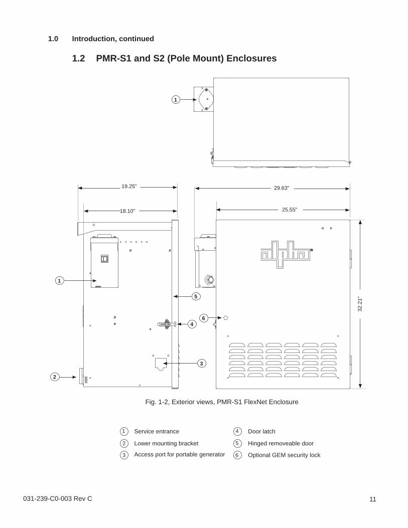
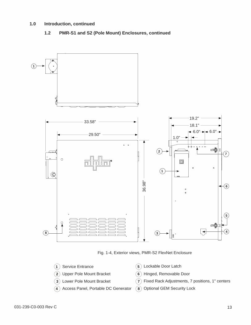
1.0 Introduction1.1 FlexNet Fiber Enclosures
The PMR (pole-mount) and GMR (ground-mount) 19" rack enclosures are equipped with AC service entrances, AC distribution, and are supported by a wide range of accessories, including Alpha’s FlexNet 300W power supply and AlphaCell 85GXL batteries. These features provide extended standby runtime and life. There are two versions of each type of enclosure available, differing only in their physical size. See Section 2.0 Specifi cations for detailed measurements.An optional fan kit is available for both PMR and GMR enclosures (see Section 4.8, Optional Fan Kit Installation), as well as an optional Form C alarm signal panel (see Section 4.9, Optional Form C Alarm Signal Panel Installation.)The FlexNet Enclosure:
Supports FTTH processors and other hardened rack-mount equipment.Supports FlexNet 300W UPS and AlphaCell batteries for reliable extended run-time.Supports thermostatically controlled 48VDC and 120VAC fan and heater options.Provides adjustable 19” EIA equipment racks — offered in either fi xed or "swing" versions.Provides a swing rack option for the PMR-S2Provides all aluminum construction with a durable powdercoat fi nishProvides a removable door and lid.
1.3 GMR-S1 and S2 (Ground Mount) Enclosures, continued
Fig. 1-8, GMR-S2 FlexNet Enclosure
4.25"
31.0"
38.0
"
20"31.0"
4
6.00"1.00"
30.4
"18.3"
1
3
2
7
5
6
18 031-239-C0-003 Rev C
Notes:
1. Additional rack space capacity if batteries are not installed.2. Runtime of 10 hours based on 212W load and new batteries.3. * Optionally confi gured items.4. **Optional items shipped separately.
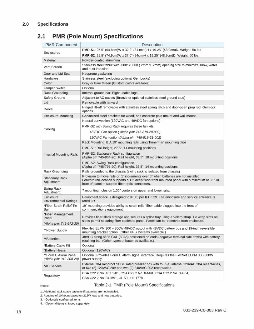
EnclosuresPMR-S1: 25.5” (64.8cm)W x 32.2” (81.8cm)H x 19.25” (48.9cm)D, Weight: 50 lbs
PMR-S2: 29.5” (74.9cm)W x 37.0” (94cm)H x 19.25” (48.9cm)D, Weight: 60 lbs. Material Powder-coated aluminum
Vent Screen Stainless steel fabric with .008” x .008 (.2mm x .2mm) opening size to minimize snow, water and dust intrusion
Door and Lid Seal Neoprene gasketingHardware Stainless steel (excluding optional GemLocks)Color: Gray or Pine Green (Custom colors available) Tamper Switch OptionalRack Grounding Internal ground bar: Eight usable lugsSafety Ground Adjacent to AC outlets (Bronze or optional stainless steel ground stud) Lid Removable with lanyard
Doors Hinged lift-off removable with stainless steel spring latch and door-open prop rod; Gemlock options
Enclosure Mounting Galvanized steel brackets for wood, and concrete pole mount and wall mount.
Cooling
Natural convection (120VAC and 48VDC fan options)
PMR-S2 with Swing Rack requires these fan kits:
48VDC Fan option ( Alpha p/n: 745-819-20-002) 120VAC Fan option (Alpha p/n: 745-819-21-002)
Internal Mounting Rails
Rack Mounting: EIA 19” mounting rails using Tinnerman mounting clips
Rack Grounding Rails grounded to the chassis (swing rack is isolated from chassis)
Stationary Rack Adjustment
Provision to move rails on 1” increments over 6” when batteries are not installed. Forward rail location supports a 12” deep fl ush front mounted panel with a minimum of 3.5” in front of panel to support fi ber optic connectors.
Swing Rack Adjustment: 7 mounting holes on 1.00" centers on upper and lower rails.
Enclosure Environmental Ratings
Equipment space is designed to IP X5 per IEC 529. The enclosure and service entrance is rated 3R
*Fiber Strain Relief Tie Bar
19” mounting provides ability to strain relief fi ber cable plugged into the front of communications equipment.
*Fiber Management Panel
(Alpha p/n: 745-672-20)
Provides fi ber slack storage and secures a splice tray using a Velcro strap. Tie wrap slots on sides permit securing fi ber cables to panel. Panel can be removed from enclosure.
**Power Supply FlexNet ELPM 300 – 300W 48VDC output with 48VDC battery bus and 19-inch reversible mounting bracket option. (Other UPS systems available.)
**Batteries 48VDC string of 85 GXL (50Ah) positioned on ends (negative terminal side down) with battery retaining bar. (Other types of batteries available.)
Optional. Provides Form C alarm signal interface. Requires the FlexNet ELPM 300-300W power supply.
*AC Service External 70A rainproof SUSE rated breaker box with four (4) internal 120VAC 20A receptacles, or two (2) 120VAC 20A and two (2) 240VAC 20A receptacles
RegulatoryCSA C22.2 No. 107.1-01, CSA C22.2 No. 0-M91, CSA C22.2 No. 0.4-04, CSA C22.2 No. 94-M91, UL 50, UL 1778
Table 2-1, PMR (Pole Mount) Specifi cations
031-239-C0-003 Rev C 19
Notes:1. Additional rack space capacity if batteries are not installed.2. Runtime of 10 hours based on 212W load and new batteries at +25°C.3. * Optionally confi gured items.4. **Optional items shipped separately.
Adjustment Provision to move rails on 1” increments over 6” when batteries are not installed. Forward rail location supports a 12” deep fl ush front mounted panel with a minimum of 3.5” in front of panel to support fi ber optic connectors.
Enclosure Environmental Ratings
Equipment space is designed to IP X5 per IEC 529. The enclosure and service entrance is rated 3R
*Fiber Strain Relief Tie Bar
19” mounting provides ability to strain relief fi ber cable plugged into the front of communications equipment.
*Fiber Management Panel:
(Alpha p/n: 745-672-20)
Provides fi ber slack storage and secures a splice tray using a Velcro strap. Tie wrap slots on sides permit securing fi ber cables to panel. Panel can be removed from enclosures.
**Power Supply FlexNet ELPM 300 – 300W 48VDC output with 48VDC battery bus and 19-inch reversible mounting bracket option.
**Batteries 48VDC string of 85 GXL (50Ah) positioned on ends (negative terminal side down)
**Battery Cable Kit Fused
*Battery Heater Optional (120VAC)
**Form C Alarm Panel (Alpha p/n: 012-308-20)
Optional. Provides Form C alarm signal interface. Requires the FlexNet ELPM 300-300W power supply.
*AC Service External 70A rainproof SUSE rated breaker box with four (4) internal 120VAC 20A receptacles, or two (2) 120VAC 20A and two (2) 240VAC 20A receptacles.
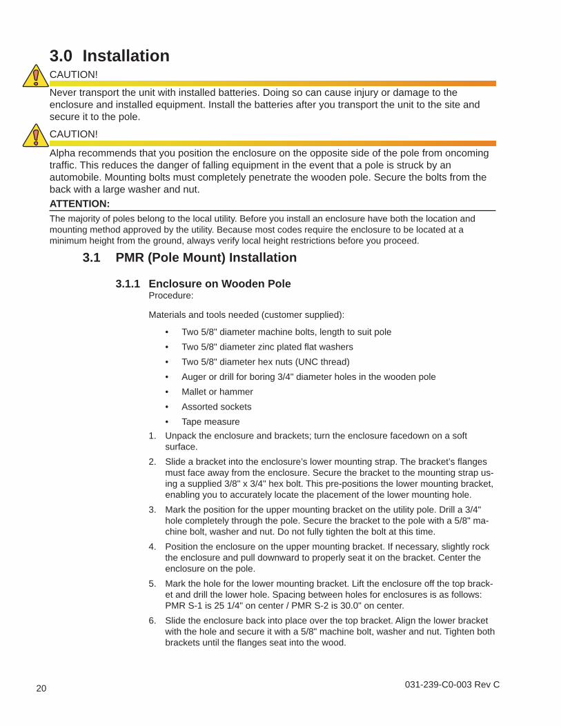
Unpack the enclosure and brackets; turn the enclosure facedown on a soft surface.Slide a bracket into the enclosure’s lower mounting strap. The bracket’s fl anges must face away from the enclosure. Secure the bracket to the mounting strap us-ing a supplied 3/8" x 3/4" hex bolt. This pre-positions the lower mounting bracket, enabling you to accurately locate the placement of the lower mounting hole.Mark the position for the upper mounting bracket on the utility pole. Drill a 3/4" hole completely through the pole. Secure the bracket to the pole with a 5/8" ma-chine bolt, washer and nut. Do not fully tighten the bolt at this time.Position the enclosure on the upper mounting bracket. If necessary, slightly rock the enclosure and pull downward to properly seat it on the bracket. Center the enclosure on the pole.Mark the hole for the lower mounting bracket. Lift the enclosure off the top brack-et and drill the lower hole. Spacing between holes for enclosures is as follows: PMR S-1 is 25 1/4" on center / PMR S-2 is 30.0" on center.Slide the enclosure back into place over the top bracket. Align the lower bracket with the hole and secure it with a 5/8" machine bolt, washer and nut. Tighten both brackets until the fl anges seat into the wood.
1.
2.
3.
4.
5.
6.
3.0 InstallationCAUTION!
Never transport the unit with installed batteries. Doing so can cause injury or damage to the enclosure and installed equipment. Install the batteries after you transport the unit to the site and secure it to the pole.
CAUTION!
Alpha recommends that you position the enclosure on the opposite side of the pole from oncoming traffi c. This reduces the danger of falling equipment in the event that a pole is struck by an automobile. Mounting bolts must completely penetrate the wooden pole. Secure the bolts from the back with a large washer and nut.ATTENTION: The majority of poles belong to the local utility. Before you install an enclosure have both the location and mounting method approved by the utility. Because most codes require the enclosure to be located at a minimum height from the ground, always verify local height restrictions before you proceed.
Procedure:
Materials and tools needed (customer supplied):
Two 5/8" diameter machine bolts, length to suit poleTwo 5/8" diameter zinc plated fl at washersTwo 5/8" diameter hex nuts (UNC thread)Auger or drill for boring 3/4" diameter holes in the wooden poleMallet or hammerAssorted socketsTape measure
•••••••
3.1 PMR (Pole Mount) Installation
3.1.1 Enclosure on Wooden Pole
21031-239-C0-002 Rev. B
3.0 Installation, continued
3.1 PMR (Pole Mount) Installation, continued
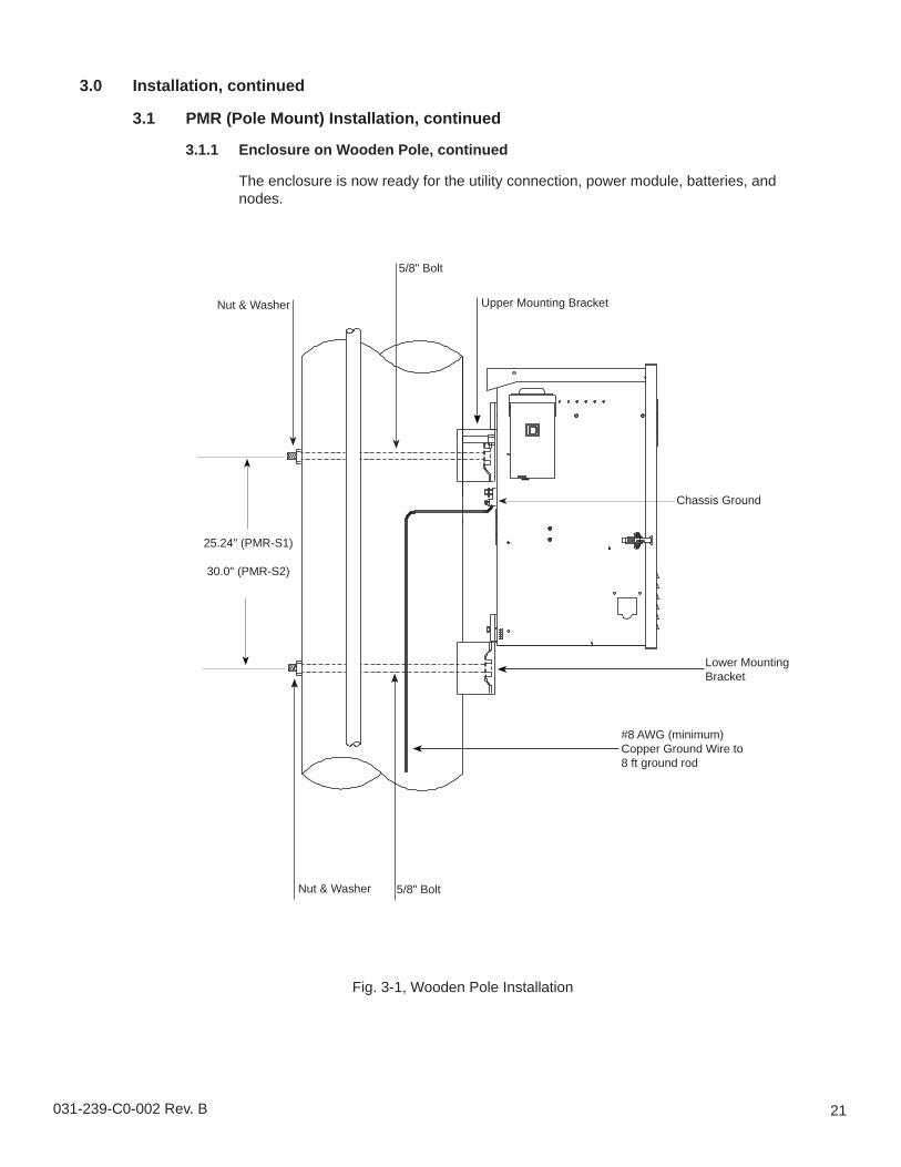
3.1.1 Enclosure on Wooden Pole, continued
The enclosure is now ready for the utility connection, power module, batteries, and nodes.
Chassis Ground
5/8" Bolt
Nut & Washer Upper Mounting Bracket
5/8" BoltNut & Washer
Lower Mounting Bracket
25.24" (PMR-S1)
30.0" (PMR-S2)
#8 AWG (minimum) Copper Ground Wire to 8 ft ground rod
Fig. 3-1, Wooden Pole Installation
22 031-239-C0-003 Rev C
Fig. 3-2, Short Wooden Pole Installation
Adhere to local codes regarding pole size, depth of hole, and fi ll material for hole and pedestal. The 8' length shown below is for reference only. Typically, one-third of the total length of the pole is buried.
3.0 Installation, continued
3.1 PMR (Pole Mount) Installation, continued
3.1.2 Enclosure on Short Pole with battery vault
You can mount the PMR enclosure on a short wooden pole, in the same manner as on a standard utility pole, with an Alpha PS-6XL pedestal used as a battery vault. The accompanying illustrations are for reference, as the exact location of the vault will be a site-specifi c decision.
NOTE:
NOTE:Install the pedestal as per the illustrations in Section 3.6 "Installing on a Polymer Pedestal Support".
NOTE:Ground the system in the same manner as described in the previous section.
1
23
4
5
6
7
96.0
"
33.5
"
30.0
"
32.0
"
2
1
3
4
5
6
7
Pole mounting bracket centered on 6"x6" pole
Grade
Fill dirt (to grade)
Concrete cap (1/3 of total depth of hole)
3/8" pea gravel (2/3 of total depth of hole)
3" of 3/8" pea gravel
5/8-11 threaded rod (10" long)
031-239-C0-003 Rev C 23
Fig. 3-3, Top View
Fig. 3-4, Connection Points
3.0 Installation, continued
3.1 PMR (Pole Mount) Installation, continued
3.1.2 Enclosure on Short Pole with battery vault, continued
Buried conduit for utility power, battery cables from vault,and node power cables (route conduit up post and secure to post). Actual location of conduit to be determined on site.
11
2
3
4
1 3/4" and 1/2" knockouts for battery vault conduit or power node cables. (4 places)
#8 AWG (min) Copper Ground Wire to 8 foot ground rod.
Utility Input Cable
Bottom of enclosure
1
2
3
4
24 031-239-C0-003 Rev C
Materials and tools:
Two customer-supplied pole straps to fi t poleAssorted sockets
Procedure:
Unpack the enclosure and galvanized brackets; turn the enclosure facedown on a soft surface.
Slide a bracket up through the enclosure’s lower mounting strap. The bracket’s fl anges must face away from the enclosure. Secure the lower mounting bracket using the 3/8” x 3/4” hex bolt included.
Position the upper mounting bracket on the pole and secure using a pole strap.
Lift the enclosure onto the upper mounting bracket and pull downward to properly seat it. Center the enclosure on the pole.
Secure the lower mounting bracket on the pole using a pole strap. Spacing between mounting straps for enclosures is: PMR-S1 is 25.24" on center. and PMR-S2 is 30.0" on center.
The enclosure is now ready for the utility connection, power module and batteries.
••
1.
2.
3.
4.
5.
6.
3.0 Installation, continued
3.1 PMR (Pole Mount) Installation, continued
3.1.3 Enclosure on Steel or Concrete Pole
031-239-C0-003 Rev C 25
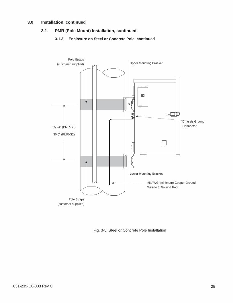
Lower Mounting Bracket
Chassis Ground Connector
Pole Straps(customer supplied) Upper Mounting Bracket
25.24" (PMR-S1)
30.0" (PMR-S2)
Pole Straps(customer supplied)
#8 AWG (minimum) Copper Ground Wire to 8' Ground Rod
Fig. 3-5, Steel or Concrete Pole Installation
3.0 Installation, continued
3.1 PMR (Pole Mount) Installation, continued
3.1.3 Enclosure on Steel or Concrete Pole, continued
26 031-239-C0-003 Rev C
3.0 Installation, continued
3.2 GMR (Ground Mount) Installations
3.2.1 Pre-Installation
Before you can install the GMR series enclosure, you must decide on the location, the type of mounting platform, and the connection and grounding options you will use. Several mounting options are available for this enclosure. You can mount an enclosure on a precast pad, pour-in-place pad using a template, or on an existing concrete pad.
Things to consider:
Provide adequate room for service personnel to remove the doors for battery installation and removal.
Wherever possible, select a site that is above the 100-year fl ood plain, and away from residences.Locate in the shade to minimize the effects of solar loading.Locate in an area where airfl ow can be maximized.Locate away from sprinkler systems or other sources of forced water.Locate out of the prevailing wind to minimize the buildup of snow or accumulation of wind-borne dust.Avoid locating the enclosure where it will be an obstruction or will inhibit visibility.Evaluate the soil conditions for suitability for the installation of the required grounding system applicable to your particular installation.Is utility power cabling run and terminated at the site?
•
•
••••
••
•
NOTE:The grounding method for a particular site will be dependent upon soil type, available space, local codes, NEC (National Electric Code), and other site-specifi c characteristics.
ATTENTION: It is the responsibility of the installer to meet the requirements of all applicable national and local codes. Alpha Technologies assumes no responsibility or liability for failure of the installer to comply with the requirements of all applicable local and national codes.
031-239-C0-003 Rev C 27
Alpha Technologies, Inc. cannot anticipate all of the ways a vehicle may potentially threaten an installed system or the specifi c type of protection that is appropriate for a particular location. The following installation drawing for Alpha’s Standby Power systems are general recommendations and not intended to be a specifi c guideline for protecting the equipment. The numbers of bollard posts (or other protection devices) depend upon equipment locations.
Fig. 3-6, GMR Positioning and Safety
PAD
POSTS
SPRINKLER HEAD
SIDEWALK
10’ (3m)
3.0 Installation, continued
3.2 GMR (Ground Mount) Installations, continued
3.2.1 Pre-Installation, continued
28 031-239-C0-003 Rev C
3.0 Installation, continued
3.3 Enclosure Grounding
Fig. 3-7, Suggested Grounding Method
Alpha Technologies assumes no responsibility or liability for failure of the installer to comply with the requirements of all applicable local and national codes. Where allowed, exothermic welding may be used as an alternative to Burndy clamps and connectors.
2 fee
t
(min)
#2 AWG
#6 AWG
Connection made with Burndy connector(P/N YGHR58C2W-3 or equivalent)
Connection made with Burndy connector(P/N YGHP58C2W-2TN or equivalent)
Two (2) 8' ground rods 6' apart minimum.Note: May require additional ground rods to meetNEC minimum grounding standard (25 Ohms or
less).
Terminate at enclosure ground
Terminate at serviceentrance ground
Alpha Technologies recommends using the grounding method illustrated below. The grounding method for a particular site will be dependant upon soil type, available space, local codes, NEC (National Electric Code), and other site-specifi c characteristics.
Alpha Technologies recommends 5 ohms minimum ground resistance between enclosure and ground rods, in accordance with IEEE 1100-1999 Powering and Grounding Electronic Equipment.
NOTE:
NOTE:
NOTE:
031-239-C0-003 Rev C 29
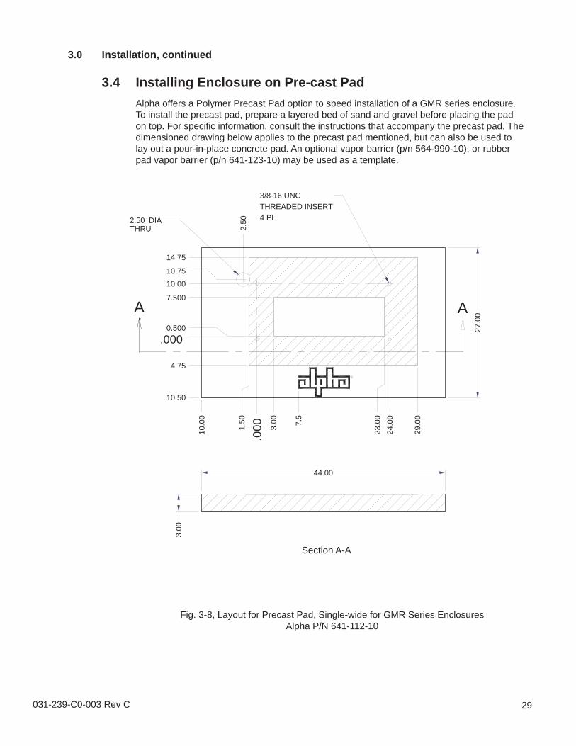
Fig. 3-8, Layout for Precast Pad, Single-wide for GMR Series EnclosuresAlpha P/N 641-112-10
.000
10.0010.75
14.75
10.50
4.75
.0001.
502.
50
3.00
23.0
024
.00
29.0
0
10.0
0
0.500
7.500
27.0
0
2.50 DIATHRU
A A
3.00
7.5
44.00
3/8-16 UNCTHREADED INSERT4 PL
Section A-A
3.0 Installation, continued
3.4 Installing Enclosure on Pre-cast PadAlpha offers a Polymer Precast Pad option to speed installation of a GMR series enclosure. To install the precast pad, prepare a layered bed of sand and gravel before placing the pad on top. For specific information, consult the instructions that accompany the precast pad. The dimensioned drawing below applies to the precast pad mentioned, but can also be used to lay out a pour-in-place concrete pad. An optional vapor barrier (p/n 564-990-10), or rubber pad vapor barrier (p/n 641-123-10) may be used as a template.
30 031-239-C0-003 Rev C
3.0 Installation, continued
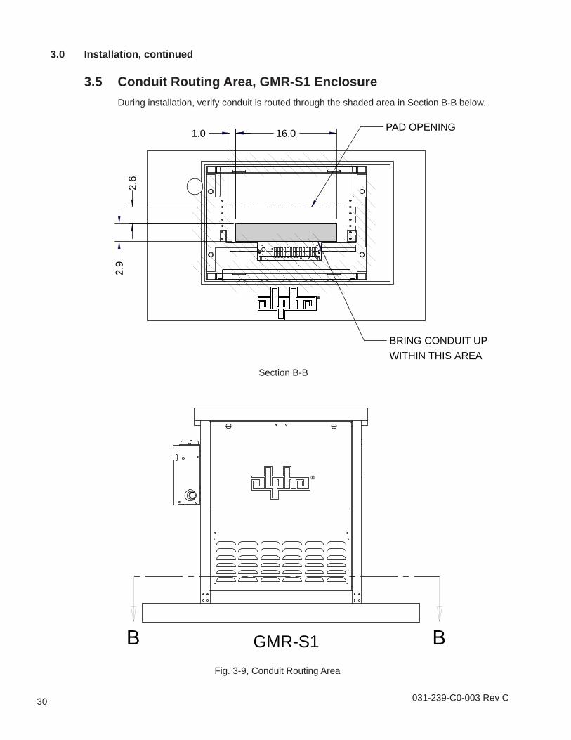
3.5 Conduit Routing Area, GMR-S1 EnclosureDuring installation, verify conduit is routed through the shaded area in Section B-B below.
Fig. 3-9, Conduit Routing Area
GMR-S1B B
®
PAD OPENING
BRING CONDUIT UPWITHIN THIS AREA
1.0 16.02.
62.
9
Section B-B
031-239-C0-003 Rev C 31
GMR-S2
BRING CONDUIT UPWITHIN THIS AREA
PAD OPENING
A A
5.2 14.8
1.6
3.9
Fig. 3-10, Conduit Routing Area
®
3.0 Installation, continued
3.6 Conduit Routing Area, GMR-S2 EnclosureDuring installation, verify conduit is routed through the shaded area in Section A-A below.
Section A-A
32 031-239-C0-003 Rev C
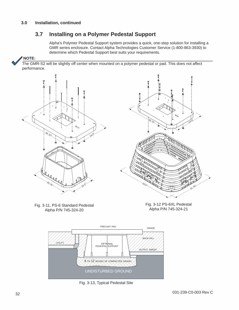
PRECAST PADGRADE
PEDESTAL SUPPORT
6 TO 12 INCHES OF COMPACTED GRAVEL
OUTPUT SWEEP
UTILITY
BACK-FILL
UNDISTURBED GROUND
Fig. 3-12 PS-6XL PedestalAlpha P/N 745-324-21
Fig. 3-11, PS-6 Standard PedestalAlpha P/N 745-324-20
Fig. 3-13, Typical Pedestal Site
25.75"
24.0"35.75"
19.2"43.5"
24.0"35.75"
31.75"
OPTIONAL
3.0 Installation, continued
3.7 Installing on a Polymer Pedestal SupportAlpha’s Polymer Pedestal Support system provides a quick, one-step solution for installing a GMR series enclosure. Contact Alpha Technologies Customer Service (1-800-863-3930) to determine which Pedestal Support best suits your requirements.
NOTE:The GMR-S2 will be slightly off center when mounted on a polymer pedestal or pad. This does not affect performance.
031-239-C0-003 Rev C 33
4.0 Equipping the System4.1 Service Power
120VAC Service Entrance Wiring
120VAC/20A Receptacle -- 5-20R
Utility power enters the enclosure through a 70 A rainproof SUSE-rated breaker box.
L1(black)
Ground(green)
Neutral(white)
to utility
neutral (white)
neutral bus
Copper ground wire#8 AWG (minimum)
L1 (black)
breaker
grounding point madeto enclosure wall
L1 (black)
to enclosurereceptacle
Use qualifi ed service personnel to connect to utility power in compliance with local electrical codes and common safety practices. Connection to utility power must be approved by the local utility before you install the power supply.UL and NEC require that a UL-listed service disconnect switch be installed between the power source and the power supply. Connection to the power supply must include an appropriate service entrance weather head.
•
•
ATTENTION:
NOTE:
Fig. 4-1, Service Power
34 031-239-C0-003 Rev C
The following precautions must be observed when maintaining batteries:
Remove all personal metal objects (watches, rings, etc.)
Use insulated tools.
Wear eye protection and rubber gloves.
Observe circuit polarities.
Do not make or break live circuits.
Do not lay metal tools and hardware on top of the batteries.The batteries are enclosed in cabinets with limited access. Again, extreme caution must be exercised when maintaining and collecting data on the battery system.Battery Identifi cationEach battery contains a DATE CODE usually located on a sticker between the battery posts. This date code must be recorded in the battery’s maintenance log. If batteries other than those installed by Alpha are used, consult the battery’s documentation for date code type and placement.
•
•
•
•
•
•
Battery systems represent a risk of electrical shock and high short circuit currents.
Battery Date Code located in this box(0605 = June 2005)
To install AlphaCell gel batteries, place the batteries (on their side) into the bottom of the enclosure with the positive terminal facing UP, and connect the battery cable kit as shown. For detailed instructions, refer to the instruction sheet that accompanies the Battery Cable Kit.
4.0 Equipping the System, continued
4.2 Batteries, continued
4.2.1 PMR Batteries
Batteries are placed on the fl oor of the enclosure and connected in accordance with the accompanying Battery Cable Kit instruction sheet.
NOTE:
36 031-239-C0-003 Rev C
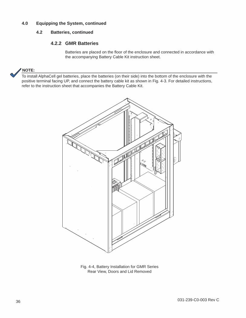
Fig. 4-4, Battery Installation for GMR SeriesRear View, Doors and Lid Removed
To install AlphaCell gel batteries, place the batteries (on their side) into the bottom of the enclosure with the positive terminal facing UP, and connect the battery cable kit as shown in Fig. 4-3. For detailed instructions, refer to the instruction sheet that accompanies the Battery Cable Kit.
4.0 Equipping the System, continued
4.2 Batteries, continued
4.2.2 GMR Batteries
Batteries are placed on the fl oor of the enclosure and connected in accordance with the accompanying Battery Cable Kit instruction sheet.
NOTE:
031-239-C0-003 Rev C 37
Fig. 4-5, Left side Mounting Rail
(as viewed from front of enclosure)
Fig. 4-6, PMR Right side Mounting Rail
(as viewed from front of enclosure)
Fig. 4-7, GMR Right side Mounting Rail
(as viewed from rear of enclosure)
PMR enclosure PMR enclosure GMR enclosure
4.0 Equipping the System, continued
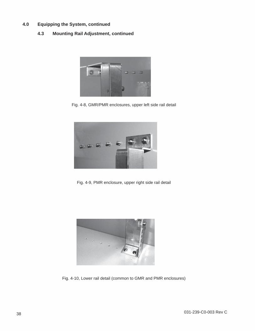
4.3 Mounting Rail AdjustmentThe equipment mounting rails are held in place by #10-32 hardware at the top and bottom of each rail. The distance between each stud (upper) and threaded hole (lower) is 1". The seven studs and seven threaded holes provide six mounting positions for specific customer applications. To reposition the rails, remove the screws or nuts and slide the rail forward or backward to the next set of holes or studs and replace the screws or nuts.
38 031-239-C0-003 Rev C
Fig. 4-8, GMR/PMR enclosures, upper left side rail detail
Fig. 4-9, PMR enclosure, upper right side rail detail
Fig. 4-10, Lower rail detail (common to GMR and PMR enclosures)
4.0 Equipping the System, continued
4.3 Mounting Rail Adjustment, continued
031-239-C0-003 Rev C 39
4.0 Equipping the System, continued
4.4 Power Supply InstallationThe power supply can be mounted on four studs located on the upper left wall of the enclosure (for S2 enclosures) or on the mounting rail (for S1 and S2 enclosures). Reference the following drawings for location. For detailed installation and wiring instructions, refer to the installation and operation manual that accompanies the power supply.
Optional ELPM 300W Power Supply.
9.24
"15
.96"
26.6
9"
17.4
5"
Fig.4-11, Power Supply Location, PMR, GMR-S1 Enclosure
Optional Mounting BracketP/N 745-265-20
40 031-239-C0-003 Rev C
Fig. 4-12, Power Supply Location, Enclosure Features PMR/GMR-S2 Enclosure
Ground Bar, 5 position Optional Fiber Slpice Module Optional AlphaCell 85GXL Batteries Access panel for Generator or Portable Generator
10” (25.4cm)
7
5
1
8
6
9
2
3
4
10
031-239-C0-003 Rev C 41
4.0 Equipping the System, continued
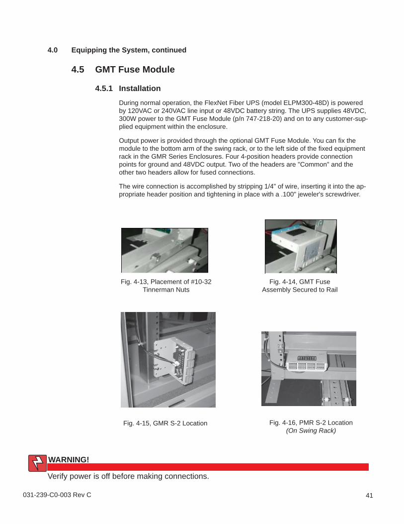
4.5 GMT Fuse Module
4.5.1 Installation
During normal operation, the FlexNet Fiber UPS (model ELPM300-48D) is powered by 120VAC or 240VAC line input or 48VDC battery string. The UPS supplies 48VDC, 300W power to the GMT Fuse Module (p/n 747-218-20) and on to any customer-sup-plied equipment within the enclosure.
Output power is provided through the optional GMT Fuse Module. You can fi x the module to the bottom arm of the swing rack, or to the left side of the fi xed equipment rack in the GMR Series Enclosures. Four 4-position headers provide connection points for ground and 48VDC output. Two of the headers are "Common" and the other two headers allow for fused connections.
The wire connection is accomplished by stripping 1/4" of wire, inserting it into the ap-propriate header position and tightening in place with a .100" jeweler's screwdriver.
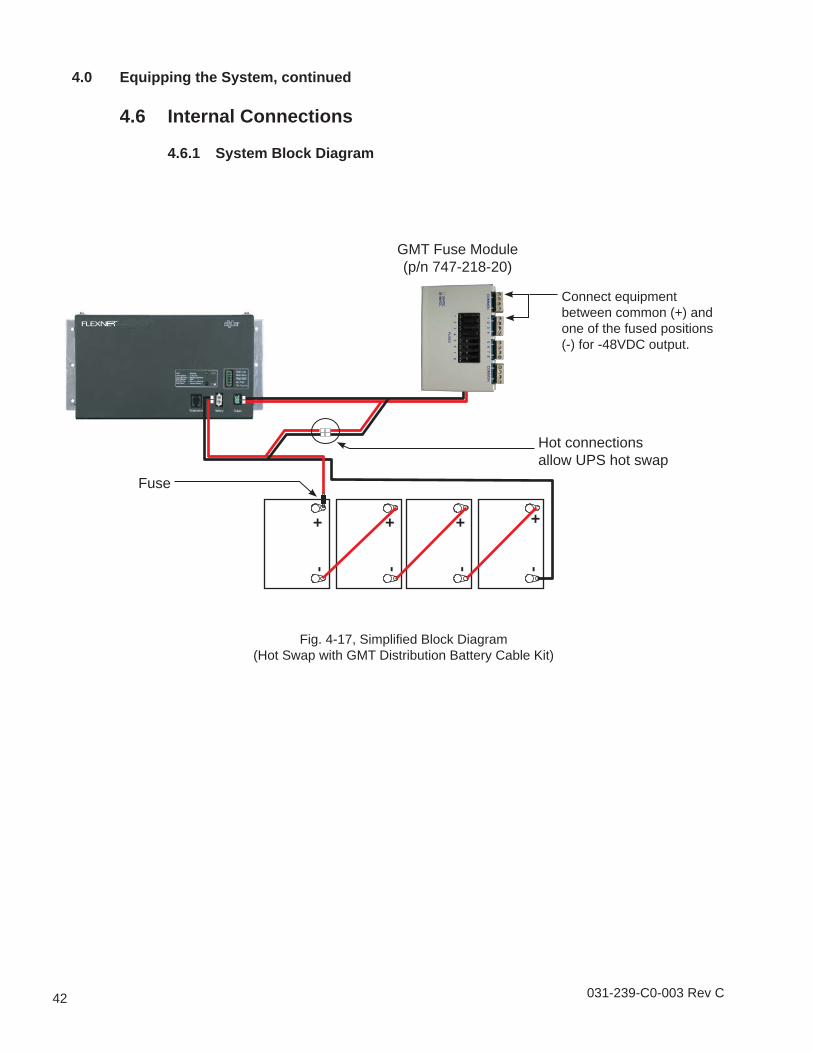
Connect equipment between common (+) and one of the fused positions (-) for -48VDC output.
4.0 Equipping the System, continued
4.6 Internal Connections
4.6.1 System Block Diagram
Fig. 4-17, Simplifi ed Block Diagram(Hot Swap with GMT Distribution Battery Cable Kit)
031-239-C0-003 Rev C 43
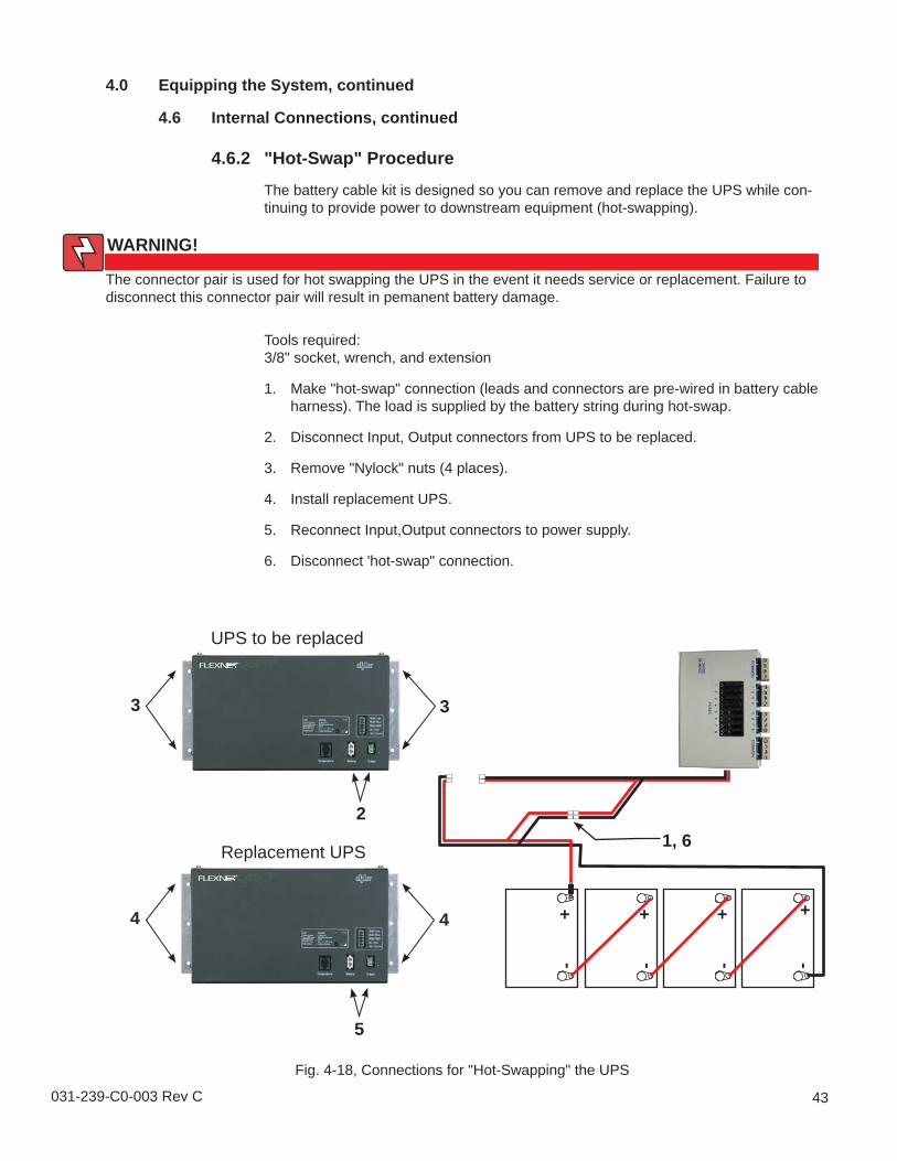
Fig. 4-18, Connections for "Hot-Swapping" the UPS
4.0 Equipping the System, continued
4.6 Internal Connections, continued
4.6.2 "Hot-Swap" Procedure
The battery cable kit is designed so you can remove and replace the UPS while con-tinuing to provide power to downstream equipment (hot-swapping).
Tools required:3/8" socket, wrench, and extension
Make "hot-swap" connection (leads and connectors are pre-wired in battery cable harness). The load is supplied by the battery string during hot-swap.
Disconnect Input, Output connectors from UPS to be replaced.
Remove "Nylock" nuts (4 places).
Install replacement UPS.
Reconnect Input,Output connectors to power supply.
Disconnect 'hot-swap" connection.
1.
2.
3.
4.
5.
6.
+
-
+
-
+
-
+
-
UPS to be replaced
Replacement UPS 1, 62
3 3
4 4
5
The connector pair is used for hot swapping the UPS in the event it needs service or replacement. Failure to disconnect this connector pair will result in pemanent battery damage.
Tie Slots Cable Clip, 5 PLC. (p/n 651-667-10) Central Member Clamp, 4 PLC.
4
56
4.0 Equipping the System, continued
4.7 Fiber Management Panel
The optional Fiber Management Panel (Alpha p/n 745-672-20) provides fiber slack storage and secures a splice tray using a Velcro strap. The side tie wrap slots permit securing fiber cables to panel.The panel is easily installed on the left side of the enclosure (as viewed from the front) and slides over two wall-mounted studs at the top of the panel, held in place by #10-32 screws, and secured by a wingnut at the center bottom of the panel.
031-239-C0-003 Rev C 45
4.0 Equipping the System, continued
4.8 Optional Fan Kit InstallationThe 48VDC and 120VAC fan option for PMR and GMR Series enclosures supplies cooling for equipment rated to 55°C (131°F) ambient internal temperature. See Section 2.1 and 2.2 for Alpha part numbers and specifi cations.The fan unit mounts easily inside the enclosure by sliding the fl anges, located at the rear of the unit, into the slot on the back wall of the enclosure and then extending the side rails until they are secure.
5
4
3
2
1
Fig.4-20, Optional Fan Kit
1
2
3
4
5
Power Cord
Wiring Kit
Right-side Rear Flange*
Right-side Fan*
Right-side Sliding Rail*
*Note the corresponding component on the left-side of the unit
46 031-239-C0-003 Rev C
4.0 Equipping the System, continued
4.8 Optional Fan Kit Installation, continued
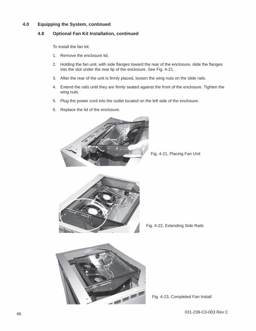
To install the fan kit:
Remove the enclosure lid.
Holding the fan unit, with side fl anges toward the rear of the enclosure, slide the fl anges into the slot under the rear lip of the enclosure. See Fig. 4-21.
After the rear of the unit is fi rmly placed, loosen the wing nuts on the slide rails.
Extend the rails until they are fi rmly seated against the front of the enclosure. Tighten the wing nuts.
Plug the power cord into the outlet located on the left side of the enclosure.
Replace the lid of the enclosure.
1.
2.
3.
4.
5.
6.
Fig. 4-21, Placing Fan Unit
Fig. 4-22, Extending Side Rails
Fig. 4-23, Completed Fan Install
031-239-C0-003 Rev C 47
4.0 Equipping the System, continued
4.9 Optional Form C Alarm Panel InstallationThe PMR and GMR Series enclosures can be modifi ed to supply Form C alarm signals. The optional Form C Alarm Panel installs easily into the equipment mounting rack and plugs into the ELPM 300W power supply, using supplied wiring kits. See Section 2.1 and 2.2 for part numbers and specifi cations and the ELPM 300 manual for specifi c information on the power supply.
Fig. 4-24, Form C Alarm Signal Panel
1 2 3 4 5
1
2
3
4
5
Plug into the AC Power outlet at the rear of the enclosure
Plug into the Status Monitoring connector on the ELPM front panel
Plug into the Output connector on the ELPM front panel
Provides connection for customer-supplied monitoring equipment.Provides for customer-supplied alarm monitoring with the addition of a "Rectifi er Fail" alarm.
19.00
18.12
1.98
1.00
Fig. 4-25, Form C Alarm Signal Panel Dimensions
48 031-239-C0-003 Rev C
4.0 Equipping the System, continued
4.9 Optional Form C Alarm Panel Installation, continued
4.9.1 Mounting and Wiring the Alarm Panel
Fasten the panel to the rack using the screws supplied with the rack system.
Make the following connections from the front of the alarm panel to the front panel of the ELPM, using the appropriate wires from the wire kit. See Fig. 4-26 for details.
1.
2.
Fig. 4-26, Attach panel to rack
From Alarm Panel To ELPM Power SupplyLine Sense AC PowerTo ELPM Alarm Status monitoring connectorTo ELPM Output Output
Table 4-1, Connections for Alarm Panel
Fig. 4-27, Wiring the Alarm Panel
Complete the VOut and Alarm connections (see Fig. 4-24) to your monitoring equipment.