http://www.iaeme.com/IJCIET/index.asp 452 [email protected]
International Journal of Civil Engineering and Technology (IJCIET) Volume 8, Issue 2, February 2017, pp. 452–469 Article ID: IJCIET_08_02_048
Available online at http://www.iaeme.com/IJCIET/issues.asp?JType=IJCIET&VType=8&IType=2
ISSN Print: 0976-6308 and ISSN Online: 0976-6316
© IAEME Publication Scopus Indexed
FLEXURAL BEHAVIOUR OF RC BEAM WRAPPED
WITH GFRP SHEETS
T.P. MEIKANDAAN
Research Scholar, Dept of Civil Engineering,
Bharath University, Chennai, Tamilnadu, India
Dr. A. RAMACHANDRA MURTHY
*Senior Scientist CSIR -Structural Engineering Research Centre
Taramani, Chennai-113, Tamil Nadu, India
ABSTRACT
Repair and strengthening of R.C beam is now becoming more and more important in the field of
structural strengthening and retrofitting. The present paper reviews the study of Glass Fiber
Reinforced Polymer (GFRP) flats under flexural behavior in reinforced concrete beams. In this study,
experimental investigation on the flexural behavior of RC Beam has been studied by wrapping Glass
Fiber Reinforced Polymer (GFRP) sheets. Reinforced Concrete Beam externally bonded with GFRP
sheets were tested to failure using a symmetrical two point static loading system. Six Reinforced
Concrete Beams have been cast for this experimental test. All cast beams are weak in flexural and
having same reinforcement detailing. Three beams are used as control beams and three beams are
strengthened using full bottom of glass fiber reinforced polymer (GFRP) sheets. The experimental
result shows, that full bottom GFRP sheet wrapping in 70% preloaded beam can increase flexural
capacity of the beam by 14%(on ultimate load) as compared to Controlled Beams.
Key words: Glass Fibre Reinforced Polymer, Concrete Beams, Flexural Strengthening, Deflection.
Cite This Article: T.P. Meikandaan and Dr. A. Ramachandra Murthy, Flexural Behaviour of RC
Beam Wrapped with GFRP Sheets. International Journal of Civil Engineering and Technology, 8(2),
2017, pp. 452–469.
http://www.iaeme.com/IJCIET/issues.asp?JType=IJCIET&VType=8&IType=2
1. INTRODUCTION
1.1. GENERAL
Reinforced cement concrete is an extremely popular construction material used for structural components of
a building like beams, columns and slabs etc. One major flaw of RCC is its susceptibility to environmental
attack. This can severely decrease the strength and life of the structures. The repair of structurally deteriorated
RC Structures become necessary since the structural element ceases to provide satisfactory strength and
serviceability. Some of these structures are in such a bad condition that they need to be replaced. Two
T.P. Meikandaan and Dr. A. Ramachandra Murthy
http://www.iaeme.com/IJCIET/index.asp 453 [email protected]
techniques are typically adopted for the strengthening of beams, relating to the strength enhancement desired:
flexural strengthening or shear strengthening. In many cases it may be necessary to provide both strength
enhancements. For the flexural strengthening of a beam, FRP sheets or plates are applied to the tension face
of the member (the bottom face for a simply supported member with applied top loading or gravity loading).
Principal tensile fibers are oriented in the beam longitudinal axis, similar to its internal flexural steel
reinforcement. This increases the beam strength and its stiffness (load required to cause unit deflection),
however decreases the deflection capacity and ductility.
1.2. BACKGROUND
A large number of structures constructed in the past using the older design codes in the different parts of the
world are structurally unsafe according to the new design codes. Since replacement of such deficient elements
of structures incurs a huge amount of public money and time, strengthening has become the acceptable way
of improving the load carrying capacity and service lives. Wrapping Techniques of Flexural concrete
elements is traditionally accomplished by externally bonding steel plates to concrete. Although this technique
has proved to be effective in increasing strength and stiffness of RC Beam, it has the disadvantages being
susceptible to corrosion and difficulty in installation.
Recent developments in the field of composite materials together with their inherent properties which
include high tensile strength, good fatigue strength, corrosion resistance, ease of use make them an alternative
to the steel plates in the field of repair and strengthening of concrete beams.
For the past studies conducted it has been shown that externally bonded glass fiber reinforced polymers
(GFRP) can be used to increase or enhance the Flexural Strength, shear strength, and torsional capacity of
RC beams.
1.3. AIM
The major aim of the project is to study the behavior of R.C.C. beams retrofitted with GFRP overlays so that
to obtain best procedures for strengthening of R.C.C. beams using GFRP overlays. To improve the load
carrying capacity of the R.C.C Beam using GFRP overlays is the aim of the project
1.4. OBJECTIVES
1. To study the ductility of flexural deficient beams
2. To study the effect of different sized layers of GFRP, which can be wrapped on both shear deficient beams and
flexural deficient beams
3. To compare the strength of various layers of GFRP which can be wrapped on beams
1.5. SCOPE OF STUDY
The investigations as well as studies conducted on the retrofitting of the RCC beams using Glass Fiber
reinforced polymer overlays are limited. So it is essential to study the shear carrying capacity, Flexural
carrying capacity and ductility of flexural beams by retrofitting with GFRP.
1.6. FACTORS TO BE CONSIDERED FOR STRENGTHENING OF BEAMS:
• Magnitude of strength increase
• Effect of change in relative member stiffness
• Size of the project
Flexural Behaviour of RC Beam Wrapped with GFRP Sheets
http://www.iaeme.com/IJCIET/index.asp 454 [email protected]
1.7. APPLICATION OF GFRP OVERLAYS FOR STRENGTHENING OF RC BEAMS
1.7.1. Fiber Reinforced Polymer (FRP)
Fiber reinforced polymer (FRP) composites are formed by embedding continuous Fibers in a resin matrix
that binds the Fibers together.
1.7.2. Types of FRPs
Depending on the Fibers used, FRP composites are classified into three types: Glass FRP composites (GFRP),
Carbon FRP composites (CFRP) and Aramid FRP composites (AFRP).
Although FRP composites are expensive and more susceptible to physical damage than steel, they have
become an attractive substitute for steel in strengthening systems for concrete structures due to their many
advantages, high strength to weight ratio, corrosion resistance, High fatigue resistance, easy and reliable
surface preparation.
1.7.3. FRP Composite
Fiber Reinforced Polymer composite is defined as a polymer (plastic) matrix, either thermo set or
thermoplastic, that is reinforced (combined) with a fiber or other reinforcing material with a sufficient aspect
ratio(length to thickness) to provide a discernable reinforcing function in one or more directions
1.7.4. GFRP Sheets
Application of GFRP overlays is the one of the simplex methods for wrapping the existing structures. GFRP
has high strength ratio high stiffness to weight ratio, flexibility in design, non corrosiveness, high ultimate
strength and lower density.
1.8 ADVANTAGES AND LIMITATIONS OF GFRP OVERLAYS FOR
STRENGTHENING OF BEAMS
1.8.1 Advantages
1. Low cost when compared to other FRPs
2. High Strength to weight ratio
3. Corrosion resistance
1.8.2. Disadvantages
1. The main disadvantage of externally strengthening structures with Composite materials is the risk of fire,
vandalism or accidental, damage, unless the strengthening is protected.
2. Compressive strength is lower than tensile strength.
3. The lack of experience of the techniques and suitably qualified staff to
1.10. GFRP WRAPPING PROCESS
While doing the wrapping process, first the beams were washed with acetone to remove the dust, dirt and
were made clean. The surfaces of the beams were rubbed with paper to make the surface rough. Then
wrapping of GFRP sheets on the surface of the beams were done. The wet lay up or hand layup technique
will be adopted. Concrete beams strengthened with glass Fiber fabric were cured for 48 hours at room
temperature before testing.
T.P. Meikandaan and Dr. A. Ramachandra Murthy
http://www.iaeme.com/IJCIET/index.asp 455 [email protected]
1.11. Epoxy adhesives
• Strong adhesive to bonded elements.
• Strong cohesion.
• Little tendency to creep under load.
2. LITERATURE REVIEW
2.1. INTRODUCTION
This section deals with the study of investigations done on applications of Fiber Reinforced Polymer (FRP)
plates especially GFRP overlays used for strengthening of reinforced concrete beams. Investigations were
done by wrapping GFRP over lays to the RCC beams and tested for load carrying capacity of beams.
2.2. SUMMARY OF LITERATURE
From the above literature review it is observed that by use of GFRP overlays there is the considerable increase
in flexural strength. The ultimate load carrying capacity of retrofitted flexural deficient beams was improved
by 5% to 20% depending upon the number of layers and type of overlays and in the case of shear deficient
beams it varies from 2.5% to 15% depending upon the number of layers and type of overlays. These
deficiencies occurs due to several reasons such as insufficient shear reinforcement or reduction in steel, due
to corrosion, increased due to load and due to construction defects therefore to reduce or to minimize these
deficiencies externally bonded reinforcement such as Glass Fiber Reinforced Polymer is an excellent solution
in these situation.
3. METHODOLOGY
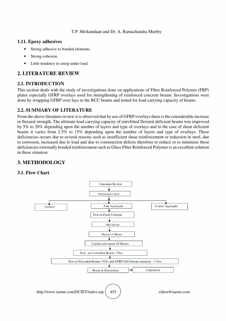
3.1. Flow Chart
Flexural Behaviour of RC Beam Wrapped with GFRP Sheets
http://www.iaeme.com/IJCIET/index.asp 456 [email protected]
3.2. MATERIALS
3.2.1. Cement
Portland Pozzolona Cement (PPC)-53 grade was used for the investigation. It was tested for its physical
properties in accordance with Indian Standard specifications.
3.2.2. Fine Aggregate
The sand used for experimental program was locally procured and conforming to zone II. The sand was first
sieved through 4.75 mm sieve to remove any particles greater than 4.75 mm. It was tested as per Indian
Standard Specification IS: 383-1970. The specific gravity coarse aggregate are 2.6
3.2.3. Coarse Aggregate
Locally available coarse aggregates were used in this work. Aggregates passing through 20mm sieve and
retained on 16mm sieve were sieved and tested as per Indian Standard Specifications IS: 383-1970. The
specific gravity coarse aggregate are 2.65
3.2.4. Water
The tap water available in the campus was tested for its suitability. Necessary properties such as pH value,
chloride content, total hardness and total dissolved solids were evaluated.
3.2.5. Reinforcing Steel
HYSD bars of 8 mm φ were used as main reinforcement. 6 mm φ mild steel bars were used for shear
reinforcement.
3.2.6. Fiber Reinforced Polymer (FRP)
Continuous fiber-reinforced materials with polymeric matrix (FRP) can be considered as composite,
heterogeneous, and anisotropic materials with a prevalent linear elastic behavior up to failure. They are
widely used for strengthening of civil structures. There are many advantages of using FRPs:
lightweight, good mechanical properties, corrosion-resistant, etc. Composites for structural
strengthening are available in several geometries from laminates used for strengthening of members with
regular surface to bidirectional fabrics easily adaptable to the shape of the member to be strengthened.
3.2.6.1. Glass fiber
Glass fibers are also available as thin sheets, called mats. A mat may be made of both long continuous and
short fibers (e.g., discontinuous fibers with a typical length between 25 and 50 mm), randomly arranged and
kept together by a chemical bond. The width of such mats is variable between 5 cm and 2 m, their density
being roughly 0.5 kg/m2. Glass fibers typically have a Young modulus of elasticity (70 GPa for E-glass)
lower than carbon or aramid fibers and their abrasion resistance is relatively poor; therefore, caution in their
manipulation is required. In addition, they are prone to creep and have low fatigue strength. To enhance the
bond between fibers and matrix, as well as to protect the fibers itself against alkaline agents and moisture,
fibers undergo sizing treatments acting as coupling agents. Such treatments are useful to enhance durability
and fatigue performance (static and dynamic) of the composite material. FRP composites based on fiberglass
are usually denoted as GFRP.
3.2.7. Resin
Epoxy resin is used for wrapping the specimens with GFRP.
T.P. Meikandaan and Dr. A. Ramachandra Murthy
http://www.iaeme.com/IJCIET/index.asp 457 [email protected]
3.2.7.1. Epoxy Adhesive
The Sikadur 30 epoxy resin is a thixotropic adhesive mortar, based on a two-component solvent free epoxy
resin. The mixing ratio was 3:1 of Component A (resin) and Component B (hardener) by weight. The elastic
modulus, tensile strength, and shear strength as provided by the manufacturer are 11.7 GPa, 24.8 MPa, and
15 MPa, respectively.
3.2.9. Accelerator
It is used along with catalyst to harden the resin from liquid states to solid states.
3.2.9. Catalyst
Catalyst increases the rate of a chemical reaction of two or more reactants and helps in rapid hardening of the
mix
3.2.10. Pigment
A pigment is a material that changes the colour of mix. White pigment is used for wrapping the specimens
with GFRP.
3.3. TEST PROGRAM
3.3.1.
In nominal mix concrete, properties of ingredients are not considered and same is limited up-to M20 grade
only. For present work, Portland Pozzolana Cement (PPC) was used in nominal and design mixed M20 grade
concrete and required angular aggregate and zone III river sand, nominal mix concrete (1.0 : 1.60: 2.75) was
prepared. Density and cement content of fresh concrete were 2217.00 kg/m3 and 413 kg/m3 respectively.
3.3.2. PREPERATION OF MOULD
Fresh concrete, being plastic requires some kind of form work to mould it to the required shape and also to
hold it till it sets. The form work has, therefore, got to be suitably designed. It should be strong enough to
take the dead load and live load, during construction and also it must be rigid enough to withstand any
bulging, twisting or sagging due to the load.
4. EXPERIMENTAL SETUP AND TESTING
4.1. EXPERIMENTAL SETUP
Six specimens are prepared for this experiment using cement, fine aggregate and coarse aggregate for which
the designs mix proportion is arrived. To investigate the ultimate load carrying capacity of beam, specimens
are prepared and designated as follows.
• CB– Control Beam specimens 3 for flexural.
• Wrapped beam – Beam specimen with bottom full layer of GFRP for 70% preloading.
Preliminary tests are carried as per IS standard on the material used for concrete like specific gravity,
fineness, consistency, and initial setting time for cement. For fine and coarse aggregates tests such as sieve
analysis, specific gravity, impact value, crushing value and abrasion value (Los Angeles) are conducted as
per standards and results are tabulated.
Flexural Behaviour of RC Beam Wrapped with GFRP Sheets
http://www.iaeme.com/IJCIET/index.asp 458 [email protected]
The ingredients of concrete such as cement, fine aggregate, coarse aggregate of maximum nominal size
of 20mm are weighed accurately using the platform weighing machine. The ingredients are mixed manually
and adequate amount of water is added to the constituents of concrete.
4.1.1. Casting of Specimen
The dimension of the beam specimens to be prepared is 1500mm x 200mm x 100mm as shown in figure
specimens has to be casted for this experiment using M20 grade of concrete. A standard curing will be done
for 28 days after the casting of specimens.
Figure 4.1.1. Typical diagram of beam dimension
4.1.2. Wrapping of Specimen with GFRP
Glass fiber reinforced polymer will be wrapped in bottom full layers at the length of the beam specimen. Out
of 6 specimens, 3 specimens will be used as control beam specimen and the rest 3 will be wrapped with
GFRP in bottom full layer in the specimen.
Figure 4.1.2 Wrapping of beam specimen
4.2. Testing of Specimen
The specimens will be tested to find the ultimate load carrying capacity and displacement of beam specimens.
4.2.1. Form work
Fresh concrete, being plastic requires some kind of form work to mould it to the required shape and also to
hold it till it sets. The form work has, therefore, got to be suitably designed. It should be strong enough to
take the dead load and live load, during construction and also it must be rigid enough so mat any bulging,
twisting or sagging due to the load if minimized, Wooden beams, mild steel sheets, wood, and several other
materials can also be used. Formwork should be capable of supporting safely all vertical and lateral loads
that might be applied to it until such loads can be supported by the ground, the concrete structure, or other
construction with adequate strength and stability. Dead loads on formwork consist of the weight of the forms
and the weight of and pressures from freshly placed concrete. Live loads include weights of workers,
equipment, material storage, and runways, and accelerating and braking forces from buggies and other
placement equipment.
Figure 4.2.1.B Reinforcement setting
T.P. Meikandaan and Dr. A. Ramachandra Murthy
http://www.iaeme.com/IJCIET/index.asp 459 [email protected]
4.2.2. Mixing of Concrete
Mixing of concrete should be done thoroughly to ensure that concrete of uniform quantity is obtained. Hand
mixing is done in small works, while machine mixing is done for all big and important works. Although a
machine generally does the mixing, hand mixing sometimes may be necessary. Use either a hoe or a square-
pointed D-handled shovel to mix the materials. Turn the dry materials at least three times until the color of
the mixture is uniform. Add water slowly while you turn the mixture again at least three times, or until you
obtain the proper consistency. Usually 10% extra cement is added in case of hand mixing to account for
inadequacy in mixing.
Figure 4.2.2 Mixing of Concrete
4.2.3. Compaction
All specimens were compacted by using needle vibrator for good compaction of concrete. Sufficient care
was taken to avoid displacement of the reinforcement cage inside the form work. Finally the surface of the
concrete was leveled and finished and smoothened by metal trowel and wooden float.
Figure 4.2.3 Concrete Mould
4.2.4. Curing Of Concrete
The concrete is cured to prevent or replenish the loss of water which is essential for the process of hydration
and hence for hardening. Also curing prevents the exposure of concrete to a hot atmosphere and to drying
winds which may lead to quick drying out of moisture in the concrete and thereby subject it to contraction
stresses at a stage when the concrete would not be strong enough to resists them.
Figure 4.2.4 Curing of Beams
4.3. EXPRERIMENTAL SETUP IN LABORATORY
All the specimens were tested in the loading frame of the “Structural Engineering” Laboratory Bharath
University, Chennai. The testing procedure for the entire specimen was same. After the curing period of
28 days was over, the beam as washed and its surface was cleaned for clear visibility of cracks. The most
commonly used load arrangement for testing of beams will consist of two-point loading. This has the
Flexural Behaviour of RC Beam Wrapped with GFRP Sheets
http://www.iaeme.com/IJCIET/index.asp 460 [email protected]
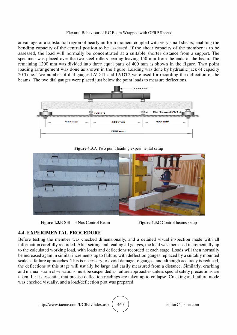
advantage of a substantial region of nearly uniform moment coupled with very small shears, enabling the
bending capacity of the central portion to be assessed. If the shear capacity of the member is to be
assessed, the load will normally be concentrated at a suitable shorter distance from a support. The
specimen was placed over the two steel rollers bearing leaving 150 mm from the ends of the beam. The
remaining 1200 mm was divided into three equal parts of 400 mm as shown in the figure. Two point
loading arrangement was done as shown in the figure. Loading was done by hydraulic jack of capacity
20 Tone. Two number of dial gauges LVDT1 and LVDT2 were used for recording the deflection of the
beams. The two dial gauges were placed just below the point loads to measure deflections.
Figure 4.3.A Two point loading experimental setup
Figure 4.3.B SEI – 3 Nos Control Beam Figure 4.3.C Control beams setup
4.4. EXPERIMENTAL PROCEDURE
Before testing the member was checked dimensionally, and a detailed visual inspection made with all
information carefully recorded. After setting and reading all gauges, the load was increased incrementally up
to the calculated working load, with loads and deflections recorded at each stage. Loads will then normally
be increased again in similar increments up to failure, with deflection gauges replaced by a suitably mounted
scale as failure approaches. This is necessary to avoid damage to gauges, and although accuracy is reduced,
the deflections at this stage will usually be large and easily measured from a distance. Similarly, cracking
and manual strain observations must be suspended as failure approaches unless special safety precautions are
taken. If it is essential that precise deflection readings are taken up to collapse. Cracking and failure mode
was checked visually, and a load/deflection plot was prepared.
T.P. Meikandaan and Dr. A. Ramachandra Murthy
http://www.iaeme.com/IJCIET/index.asp 461 [email protected]
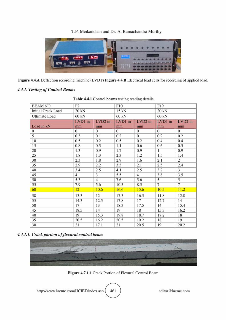
Figure 4.4.A Deflection recording machine (LVDT) Figure 4.4.B Electrical load cells for recording of applied load.
4.4.1. Testing of Control Beams
Table 4.4.1 Control beams testing reading details
BEAM NO F2 F10 F19
Initial Crack Load 20 kN 15 kN 20 kN
Ultimate Load 60 kN 60 kN 60 kN
Load in kN
LVD1 in
mm
LVD2 in
mm
LVD1 in
mm
LVD2 in
mm
LVD1 in
mm
LVD2 in
mm
0 0 0 0 0 0 0
5 0.3 0.1 0.2 0 0.2 0.2
10 0.5 0.2 0.5 0.2 0.4 0.4
15 0.8 0.5 1.1 0.6 0.6 0.5
20 1.3 0.9 1.7 0.9 1 0.9
25 1.8 1.3 2.3 1.2 1.5 1.4
30 2.3 1.8 2.9 1.6 2.1 2
35 2.9 2.2 3.5 2.1 2.5 2.4
40 3.4 2.5 4.1 2.5 3.2 3
45 4 3 5.5 4 3.8 3.5
50 5.3 4 7.6 5.6 5 5
55 7.9 5.6 10.3 8.5 7 7
60 12 10.6 16.6 15.6 10.5 11.2
58 13.3 12 17.3 16.5 11.8 12.8
55 14.3 12.5 17.8 17 12.7 14
50 17 13 18.3 17.5 14 15.4
45 18.5 14 19 18 15.3 16.2
40 19 15.3 19.8 18.7 17.2 18
35 20.5 16.2 20.5 19.2 18 19
30 21 17.1 21 20.5 19 20.2
4.4.1.1. Crack portion of flexural control beam
Figure 4.7.1.1 Crack Portion of Flexural Control Beam
Flexural Behaviour of RC Beam Wrapped with GFRP Sheets
http://www.iaeme.com/IJCIET/index.asp 462 [email protected]
4.4.1.2. Load vs deflection grape for control beams
Figure Load Vs Deflection Curve for Control Beam # F2 Figure Load Vs Deflection Curve for Control Beam # F1
0Figure c Load Vs Deflection Curve for Control Beam # F19
4.5. STRENGTHENING OF BEAMS
Before bonding the composite fabric onto the concrete surface, the required region of concrete surface was
made rough using a coarse sand paper texture and cleaned with an air blower to remove all dirt and debris.
Once the surface was prepared to the required standard, the epoxy resin was mixed in accordance with
manufacturer’s instructions. Mixing was carried out in a plastic container (Araldite LY 556 – 100 parts by
weight and Hardener HY 951 – 8 parts by weight) and was continued until the mixture was in uniform colour.
When this was completed and the fabrics had been cut to size, the epoxy resin was applied to the concrete
surface. The composite fabric was then placed on top of epoxy resin coating and the resin was squeezed
through the roving of the fabric with the roller. Air bubbles entrapped at the epoxy/concrete or epoxy/fabric
interface were to be eliminated. Then the second layer of the epoxy resin was applied and GFRP sheet was
then placed on top of epoxy resin coating and the resin was squeezed through the roving of the fabric with
the roller and the above process was repeated. During hardening of the epoxy, a constant uniform pressure
was applied on the composite fabric surface in order to extrude the excess epoxy resin and to ensure good
contact between the epoxy, the concrete and the fabric. This operation was carried out at room temperature.
Concrete beams strengthened with glass fiber fabric were cured for 24 hours at room temperature before
testing.
T.P. Meikandaan and Dr. A. Ramachandra Murthy
http://www.iaeme.com/IJCIET/index.asp 463 [email protected]
Figure 4.5.A 70% Flextural Pre loading Beam
Figure 4.5.B Clean up with salt paper Figure 4.8.C Sika 30 epoxy resin mixing
Figure 4.5.C GFRP Laminate sheet fixing with sika grow
Figure 4.5 D Flextural 70 % Preloading GFRP Bottom full Wrapping Beam Setup
Flexural Behaviour of RC Beam Wrapped with GFRP Sheets
http://www.iaeme.com/IJCIET/index.asp 464 [email protected]
4.8.1. Testing of Flexural Bottom Full Wrapping Beams
Table 4.8.1 Flexure bottoms full GFRP Sheet wrapping after pre-loading beams testing reading details
BEAM NO F21 F22 F23
Initial Crack Load 20 kN 20 kN 25 kN
ULTIMATE LOAD FOR
CONTROL BEAM 60 KN 60 KN 60 KN
ULTIMATE LOAD FOR
70 % PRE LOADING 42 kN 42 kN 41 kN
GFRP WRAPPING
POSITION IN
FLEXTURAL
BOTOM FULL LENGTH BOTOM FULL LENGTH BOTOM FULL LENGTH
Load in kN LVD1 in
mm
LVD2 in
mm
LVD1 in
mm
LVD2 in
mm
LVD1 in
mm
LVD2 in
mm
0 0 0 0 0 0 0
5 0.2 0.5 0.5 0.8 0.2 0.1
10 0.4 1 0.8 1 0.8 0.3
15 0.7 1.5 1 1.5 1.2 0.6
20 1.2 2.2 1.4 1.8 1.6 0.9
25 1.7 3 1.9 2.2 2.2 1.3
30 2.3 3.7 2.4 3 2.8 1.7
35 2.9 3.9 2.9 3.5 3.2 2.3
40 3.5 4.2 3.4 4 3.7 2.7
45 3.7 4.6 3.6 4.6 4.5 3
50 4.2 5.3 4 5.2 5.3 3.5
55 4.9 6 4.6 5.7 6.2 4.3
60 5.1 6.5 5.2 6.2 8.7 6
65 6.2 7.2 5.9 6.6 9.5 7.2
70 7 7.9 7 7 10.2 8.5
65 10 9 8 9 12.5 9
60 11.2 11 9.2 10.7 13.6 9.8
55 12.2 12 10.5 13 14.7 10.5
50 13 13 11.6 15.5 15.8 11.2
45 13.5 15 12.8 17 17 12.3
40 14.2 17 13.5 19 17.7 13.5
30 15.1 19 15 21 18.8 15
20 16 22 18 23 22 17
ULTIMATE LOAD FOR
WRAPPING BEAM 70 KN 65N 70 KN
% OF INCREASE 16.67 8.33 16.67
Avg % Increase 14 %
T.P. Meikandaan and Dr. A. Ramachandra Murthy
http://www.iaeme.com/IJCIET/index.asp 465 [email protected]
Fig Load vs Deflection curve for Flexural Full Bottom Wrapping Beam No: 21 Fig b Load vs Deflection curve for
Flexural Full Bottom Wrapping Beam No: 22
Fig4.8.1.1.c. Load vs Deflection curve for Flexural Full Bottom Wrapping Beam No: 23
5. RESULTS AND DISCUSSION
5.1. INTRODUCTION
This chapter describes the experimental results of SET I beams (Control Beam) and SET II beams (weak in
flexure). Their behavior throughout the static test to failure is described using recorded data on deflection
behavior and the ultimate load carrying capacity. The crack patterns and the mode of failure of each beam
are also described in this chapter. Three sets of beams were tested for their ultimate strengths. In SET I three
beams (beam no F2, F10 and F19) were tested for their ultimate strengths. In SET II three beams (beam nos
are F21, F22 and F23) were tested for 70% of pre ultimate load are tested. SET II beams F21, F22 and F23
after pre loaded using GFRP laminate sheet is strengthened only at the bottom of the beam in the flexure
zone of the beam. Deflection behavior and the ultimate load carrying capacity of the beams were noted. The
ultimate load carrying capacity of all the beams along with the nature of failure is given in Table 6.2.
5.2. FAILURE MODES
The following flexural failure modes should be investigated for an FRP-strengthened section:
• Crushing of the concrete in compression before yielding of the reinforcing steel; Strengthening of Reinforced
Concrete Beams using Glass Fiber Reinforced Polymer
• Yielding of the steel in tension followed by rupture of the FRP laminate;
• Yielding of the steel in tension followed by concrete crushing;
• Shear/tension delamination of the concrete cover (cover delamination); and
• Debonding of the FRP from the concrete substrate (FRP debonding).
A number of failure modes have been observed in the experiments of RC beams strengthened in flexure
by GFRPs. Flexural failure due to GFRP rupture and crushing of concrete at the top. Concrete crushing is
assumed to occur if the compressive strain in the concrete reaches its maximum usable strain. Rupture of the
FRP laminate is assumed to occur if the strain in the FRP reaches its design rupture strain before the concrete
reaches its maximum usable strain. Cover delamination or FRP debonding can occur if the force in the FRP
cannot be sustained by the substrate. In order to prevent debonding of the FRP laminate, a limitation should
be placed on the strain level developed in the laminate. The GFRP strengthened beam and the control beams
were tested to find out their ultimate load carrying capacity. It was found that the control beams F2, F10, &
Flexural Behaviour of RC Beam Wrapped with GFRP Sheets
http://www.iaeme.com/IJCIET/index.asp 466 [email protected]
F19 showing that the beams were deficient in flexure.. In SET II beams F21,F22 and F3, GFRP rupture and
flexural kind of failure was prominent when strengthening was done using the wrapping schemes.
Table 5.2 Ultimate load and nature of failure for SET I and SET II beams
Sr.No Type of
Beam
Beam
designation
Load at
initial crack
(KN)
Wrapping
position Ultimate
Load (KN)
Nature of
failure
1 Control
Beams
F2 20 - 60 Flexural
failure F10 15 - 60
F10 20 - 60
2
Beams
weak in
flexure
F21 20 Bottom full (
70 %
Preloading)
70 Flexural
failure +
Crushing of
concrete
F22 20 65
F23 25 70
5.3. LOAD DEFLECTION HISTORY
The load deflection history of all the beams was recorded. The deflection of each beam was compared with
that of their respective control beams. Also the load deflection behavior was compared between wrapping
schemes having the same reinforcement. It was noted that the behavior of the flexure deficient beams when
bonded with GFRP Laminates sheets were better than their corresponding control beams. The deflections
were much lower when bonded externally with GFRP Laminates sheets. The graphs comparing the deflection
of flexure deficient beams and their corresponding control beams are shown in Chapter 4 Figs 4.7.1.a to
4.7.1.c, & 4.8.1.a to 4.8.1.c. The use of GFRP sheet had effect in delaying the growth of crack formation. In
SET II when the wrapping schemes were considered it was found that the beam F21,F22 and F23 with Bottom
full wrapping of GFRP sheet had a better load deflection behavior when compared to the Set I control beam
F2,F10 and F19.
5.3.1. Loads At Initial Crack
Two point static loading was done on both SET I and SET II beams and at the each increment of the load,
deflection and crack development were observed. The load at initial crack of all the beams was observed,
recorded and is shown in & Fig 5.3.1.a & 5.3.1.b. Fewer than two point static loading of SET I beams, at
each increment of load, deflection and crack development were observed. In beam F2 & F10, initiation of
the crack takes place at a load of 20 KN. In F19 beam initiation of the crack takes place at a load of 15 KN.
In SET II Beam the crack initiation of the beam F21, & F22 was takes place at a load of 20 KN., and F23
initiation of the crack takes place at a load of 25 KN.
Figure 5.3.1.a Initial crack Curve for Control Beams Figure 5.3.1.b Initial crack Curve for Wrapping Beams
T.P. Meikandaan and Dr. A. Ramachandra Murthy
http://www.iaeme.com/IJCIET/index.asp 467 [email protected]
5.3.2. Ultimate Load Carrying Capacity
The load carrying capacity of the control beams and the strengthen beams were found out and is shown in
fig 5.3.2.a and 5.3.2.b. The control beams were loaded up to their ultimate loads. It was noted that of all 3
beams, the strengthen beams F21, F22 and F23, had the higher load carrying capacity compared to the
controlled beams F2,F10 &F 19 . Important character to be noticed about the usage of GFRP sheets is the
high ductile behavior of the beams. But the ductile behavior obtained by the use of GFRP can give us enough
warning before the ultimate failure. The use of FRP can delay the initial cracks and further development of
the cracks in the beam.
Figure 5.3.2.a Ultimate load for Control Beams Figure 5.3.2.b Ultimate load for Wrapping Beams
5.4. CRACK PATTERN
The crack patterns at collapse for the tested beams of SET I and SET II are shown in Fig.5.4. In SET I the
controlled beams are F2, F10 and F19 exhibited widely spaced and lesser number of cracks compared to
strengthened beams F21, F22 and F3. The strengthened beams F21, F22, and F23 have also shown cracks at
relatively close spacing. This shows the enhanced concrete confinement due to the GFRP strengthening. This
composite action has resulted in shifting of failure mode from flexural failure (steel yielding) in case of
controlled beam.
Figure 5.4 Crack Pattern for flexural Beams
5.5. COMPARISION OF RESULTS
The results of the two set of beams tested are shown in Table 4.7.1 & 4.8.1. The Table 5.1 shows that
failure mode, load at initial crack and ultimate load of the control beams without strengthening and the beams
strengthen with flexural bottom full GFRP sheet are presented.
The 70% damage degree beams increases load carrying capacity 14% when strengthened with 100 mm
width of 1.5m beam and 1.2mm thick of GFRP sheet in bottom full layer as compared with control beam
Flexural Behaviour of RC Beam Wrapped with GFRP Sheets
http://www.iaeme.com/IJCIET/index.asp 468 [email protected]
6. CONCLUSIONS
In this experimental investigation the flexural behavior of reinforced concrete
beams strengthened by GFRP sheets are studied. Two sets of reinforced concrete (RC)
beams, in SET I three beams for control beams weak in flexure and in SET II three beams damaged beams
strengthened by GFRP laminated sheets. From the test results and calculated strength values, the
following conclusions are drawn:
1. Initial flexural cracks appear at a higher load by strengthening the beam at soffit.
2. The ultimate load carrying capacity of the strengthened beam is 14 % more than the controlled beam.
3. Analytical analysis is also carried out to find the ultimate moment carrying capacity
and compared with the experimental results. It was found that analytical analysis
predicts lower value than the experimental findings.
4. Flexural strengthening up to the neutral axis of the beam increases the ultimate load
carrying capacity, but the cracks developed were not visible up to a higher load. Due
to invisibility of the initial cracks, it gives less warning compared to the beams
strengthen only at the soffit of the beam.
5. By strengthening up to the neutral axis of the beam, increase in the ultimate load
carrying capacity of the beam is not significant and cost involvement is almost three times compared to the
beam strengthen by GFRP sheet at the bottom only.
6. Use of FRP laminate improves load carrying capacity; delays crack formation and energy absorption capability
of beam reinforced with FRP laminates.
7. The 70% damage degree beams increases load carrying capacity 14% when strengthened with 100 mm width
and 1.2mm thick of GFRP sheet in single layer for bottom full as compared with control beam
6.1. SCOPE OF THE FUTURE WORK
• It promises a great scope for future studies. Following areas are considered for future research
• Strengthening of beam weak in shear.
• Effect on torsional strength due to retrofitting
• Developing a non linear finite element model for the analysis of the strengthened RC
• Beams using various configuration of FRP strengthening.
• Variation of beam dimension.
• Strengthening of Beam with different type of FRP (like Carbon fiber reinforced polymer),
REFERENCES
[1] Alferjani1. M.B.S et al (2013): Use of Carbon Fiber Reinforced Polymer Laminate for strengthening
reinforced concrete beams in shear: A review, International Refereed Journal of Engineering and Science
(IRJES) ISSN (Online) 2319-183X, (Print) 2319-1821 Volume 2, Issue 2(February 2013), PP.45-53
[2] AlaaMorsy et al (2013): Bonding techniques for flexural strengthening of R.C. Beams using CFRP
laminates, bonding techniques for flexural strengthening of R.C.
[3] Beams using CFRP laminates
[4] Al-Saidy.A.H et al (2009): Effect of damaged concrete cover on the structural performance of CFRP
strengthened corroded concrete beams
[5] AnumolRaju et al (2013): Retrofitting of RC Beams Using FRP, International Journal of Engineering
Research & Technology (IJERT) Vol. 2 Issue 1, And January- 2013ISSN: 2278-0181.
T.P. Meikandaan and Dr. A. Ramachandra Murthy
http://www.iaeme.com/IJCIET/index.asp 469 [email protected]
[6] Balasubramaniam.V et al (2011): Performance of Corrosion-Damaged HSC Beams
[7] Strengthened with GFRP Laminates, IJCSET |December 2011 | Vol 1, Issue 11, 718-721
[8] Chikh.N et al (2013): study of the bond behavior of concrete beam strengthened with nsmcfrp,
[9] Habibur Rahman Sobuz et al (2011) Use of carbon fiber laminates for strengthening reinforced concrete
beams in bending, international journal of civil and structural engineering Volume 2, No 1, 2011
[10] Jumaat.M.Z et al (2010): Flexural strengthening of RC continuous T beam using
[11] CFRP laminate: A review, International Journal of the Physical Sciences Vol. 5(6), pp. 619-625, June 2010
[12] Khaled A et al: FRP Repair of Corrosion-Damaged Reinforced Concrete Beams
[13] LeemaRose.A et al (2009): Strengthening of Corrosion-Damaged Reinforced Concrete Beams with Glass
Fiber Reinforced Polymer Laminates, Journal of Computer Science 5 (6): 435-439, 2009
[14] Lakshmikandhan K.N et al (2013): Damage Assessment and Strengthening o fReinforced Concrete Beams,
International Journal of Material and Mechanical Engineering (IJMME) Volume 2 Issue 2, May 2013.
[15] Mithun Kuma1r et al (2013): behavior of r.c.c. beam with circular opening strengthened by cfrp and gfrp
sheets, ijret: International Journal of Research in Engineering and Technology eISSN: 2319-1163.
[16] Murali G.et al (2011): flexural strengthening of reinforced concrete beams using FIBER reinforced
polymer laminate: a review, arpn Journal of Engineering and Applied Sciences
[17] Nikita Jain et al (2015): Strengthening Of RC Beams with Externally Bonded gfrps, IOSR Journal of
Mechanical and Civil Engineering (IOSR-JMCE) e-ISSN: 2278-1684,p-ISSN: 2320-334X, Volume 12,
Issue 2 Ver. VI (Mar - Apr. 2015), PP 139-142
[18] Nachimuthu.S et al (2015): strengthening of corroded rc beam using hybrid frp wrapping technique,
Integrated Journal of Engineering Research and Technology ISSN NO. 2348 – 6821
[19] RatanKharatmol at al: Strengthening of Beams Using Carbon FIBER Reinforced Polymer, International
Journal of Emerging Engineering Research and Technology Volume 2, Issue 3, June 2014, PP 119-125
[20] RajeshgunaR et al (2014): Experimental Study on Steel FIBER Reinforced Concrete Beams Strengthened
with FIBER Reinforced Polymer Laminates, International Journal of Engineering Science and Innovative
Technology (IJESIT) Volume 3, Issue 4, July 2014.
[21] S. Vimala and Dr. V. Khanna, Strongest Persistent Multicast Routing protocol for Reliable Transmission
in Both Ad-Hoc and Mobile Ad-Hoc Networks. International Journal of Civil Engineering and
Technology, 8(1), 2017, pp. 976–986.
[22] S. Vimala and Dr. V. Khanna, Multicast Optimal Energy Aware Routing Protocol for Manet Based on
Swarm Intelligent Techniques. International Journal of Civil Engineering and Technology, 8(1), 2017, pp.
967–975.
[23] G. Lakshmi Vara Prasad, Dr. C. Nalini and Dr. R. Sugumar, Arbitrary Routing Algorithm for Tenable
Data Assortment Accessed in Wireless Sensor Networks. International Journal of Civil Engineering and
Technology, 8(1), 2017, pp. 961–966.
[24] G. Ayyappan, Dr. C. Nalini and Dr. A. Kumaravel, Efficient Mining for Social Networks Using
Information Gain Ratio Based on Academic Dataset. International Journal of Civil Engineering and
Technology, 8(1), 2017, pp. 936–942.
[25] Sarita R. Khot et al (2015) In order to evaluate the effectiveness of using GFRP plates to strengthened
damaged beams, International Research Journal of Engineering and Technology (IRJET), Volume: 02
Issue: 03 | June-2015
[26] Ta¨ljsten.B (2003): Strengthening concrete beams for shear with CFRP sheets, Construction and Building
Materials 17 (2003) 15–26
[27] Vinodkumar.M et al (2014): Review on CFRP/ GFRP Composites used for Strengthening of Reinforced
Concrete Beams, IJREAT International Journal of Research in Engineering & Advanced Technology,
Volume 2, Issue 2, Apr-May, 2014.