Stratomaster Maxi Single Flight II Primary flight instrument The Flight II is a ultra compact, complete primary flight system intended as main flight instrument on smaller aircraft or as backup / secondary flight instrument. This 3.5” instrument provides many functions from Altimeter, Airspeed to Fuel level/flow, Engine RPM and many secondary functions, including an automatic flight log. The Flight II ‘s light weight, small size and high level of functionality in addition to excellent value for money make it an ideal choice for many applications. The Flight II makes and ideal companion to the Stratomaster E1 universal engine monitor for a compact, low cost yet highly functional and complete cockpit solution.
Transcript
Stratomaster Maxi Single
Flight II
Primary flight instrument
The Flight II is a ultra compact, complete primary flight system intended as main flight instrument on smaller aircraft or as backup / secondary flight instrument. This 3.5” instrument provides many functions from Altimeter, Airspeed to Fuel level/flow, Engine RPM and many secondary functions, including an automatic flight log. The Flight II ‘s light weight, small size and high level of functionality in addition to excellent value for money make it an ideal choice for many applications. The Flight II makes and ideal companion to the Stratomaster E1 universal engine monitor for a compact, low cost yet highly functional and complete cockpit solution.
The Flight II functions The Flight II provides the following functions:
1) Altimeter (-700ft to >40.000ft range) 2) Airspeed indicator (16-250 mph range) 3) Analog VSI (+/-1600 ft/min range) 4) Digital VSI (+/-10.000 ft/min range) 5) Automatic flight duration timer 6) Real time clock for local time and flight log use 7) Fuel flow (with optional Fuel flow sender) 8) Fuel level calculated from fuel flow 9) Fuel level obtained from optional fuel level sender 10) Multipoint fuel level sender calibration to compensate for odd shaped tanks and non-
linear fuel level senders 11) Engine RPM gauge, programmable for different engine types 12) Engine Hobbs meter, can be preset to any hour/minute setting up to 9999 hours 13) Maintenance timer (MPI, Plug changes etc) 14) Automatic flight log (logs last 60 flights) 15) Log viewer in instrument 16) Log download to PC or download key (optional accessories) 17) Temperature display with external ambient temperature probe (included) 18) Density altimeter 19) Barometer (actual local pressure) 20) True airspeed (TAS display) 21) Fuel range based on TAS 22) Fuel endurance based on TAS 23) Stopwatch 24) User programmable units: mph,km/h,knots,ft,meters,liters,gallons 25) Times can be set to minutes or decimal hour fractions 26) Glide and Climb ratio indicator 27) Alarm on low airspeed 28) Alarm on high airspeed 29) Alarm on low fuel level
The main screen of the Flight II During operation of the Flight II instrument, the following display is shown:
Operating the keys
Engine RPM display
Analog VSI
Digital VSI
System voltage
Airspeed indicator Altimeter
Active flight indicator
Auxiliary flight information display (four display pages)
Local pressure setting (QNH)
The menu key. Press this key to enter the menu system.
Enter / Select key. Used in the menu system or to select one of four auxiliary information pages from the main display screen.
Plus and minus keys. Used in the menu system. When the main display is showing these keys are used to set the local pressure (QNH). If the stopwatch page is showing, these keys are used to start/stop and reset the stopwatch.
The bottom left section of the main display is arranged in four pages. Use the “Select” (Enter) key to page between these pages.
Fuel level Fuel Flow Fuel range Fuel endurance Local time Flight time Stopwatch – when this page is showing the + and – keys control the stopwatch.
Engine hobbs meter Maintenance timer Ambient temperature Glide / climb ratio
Distance through the air trip counter True airspeed Density altimeter Barometer (actual local pressure)
The Flight II The Flight II is a multifunction primary flight instrument with Engine RPM and fuel monitoring. It is intended to be installed in a standard 3.5” instrument panel putout (front installation). 3.5” refers to the distance between the mounting holes. The hole itself is usualy a 3.1/8” size. The Flight II is intended for use as primary flight instrument in smaller aircraft with limited panel space or as secondary or backup instrument in larger aircraft. The Flight II can be combined with the MGL Avionics E1 Engine monitoring system for a very compact, full instrumentation solution at very low cost yet extremely versatile functionality. For a compact panel, in the same line of instrumentation, further instruments can could be considered are the GPS-1 panel mount GPS solution and the Stratocom wireless aircraft intercom system.
Setting up the Flight II Press the Menu key to enter the menu. You can move forward and backwards in the menu by using the + and – keys. To change or select a menu item, move the highlight to the desired item and then press the Select (Enter) key. To end an edit or function, press the Menu key again. To exit the menu and continue normal operation, press the Menu key.
Items in the main menu
Flight: Start/End/Detect If instrument is setup for automatic flight detect, then the word “Detect” appears. In this case this menu function is disabled. If your instrument is configured for manual flight detect and no flight is currently being logged, the work “Start” appears. If a flight is currently being logged (flight is active) then the word “End” will appear. Select this function to “Start” and “End” the logging of flights manually. You can select manual or automatic flight detect mode in the “Setup Operation” menu.
We recommend that you choose automatic flight logging.
Fuel level … If the instrument is operating with an external fuel level sender, then this entry will show the current fuel level, you cannot edit the entry. If you have selected to operate with a fuel flow sender only, then you can use this function to set your current fuel level. As the flow sender detects flow, the level will decrease accordingly (calculated fuel level). Units are as selected in the “Setup Units” menu (Liters or U.S. Gallons).
Trip Zero Select this function to set your air distance trip counter to zero. Note that you can select to set the counter to zero automatically as a new flight is started. Regardless of this, you can set the counter to zero at any time.
View Flight log Entering this function will allow you to view the entries in your flight log. The instrument will maintain a log of your last 60 flights. Each log entry contains date and time of your take-off, duration of the flight, maximum altitude and airspeed reached and also the reading of your engine Hobbs meter at the end of the flight.
Contrast … This function allows you to change the display contrast to your liking. You can select values from about 20 to 45. (can vary depending on display type). Typical values are around 35.
Backlight … This function allows you to switch the display backlight on or off. We recommend that you leave the backlight switched on unless you need to conserve power.
Setup Units This enters a menu where you can select units for various measurements.
Setup Operation This enters a menu where you can select the various modes of operation.
Setup Limits This enters a menu where you can set various alarm levels and operating limits.
Set time/date This function allows you to set the time and date of the internal real time clock. Please note that the internal real time clock maintains a year calendar for every leap year interval only. This means that every leap year you need to reset the year to the current year.
Set Hobbs This function allows you to set the engine Hobbs meter to any value. Typically, you would use this function to set the Hobbs meter to the current known engine time.
Set maintenance This function allows you to set a maintenance counter. This counter is set in engine hours and it will count down to zero when the engine is running. A good use for this function is to set the hours until your next spark plug change or engine inspection.
Calibration This enters a menu system containing various instrument calibration and related setup functions. You will find functions to setup your fuel tank size and calibration in here as well.
ADC This is a technical function that is used during manufacture or repair of your instrument. It shows the values obtained from an internal eight channel analog to digital converter – the bases for many of your instruments functions. This function is not normally used by the owner of the instrument.
The “Setup Units” menu Items in the calibration menu
ALT ... Select if you want your altitude readout in feet (ft) or meters (m).
QNH ... Select if you want your local pressure readout in millibars (mB) or inches or mercury (“HgA).
ASI ... Select your preferred units. You can select statute miles per hour (mph), kilometers per hour (km/h) or nautical miles per hour (knots). According to this selection your airspeed will be indicated in mph, km/h or knots.
VSI … Select if you would like the VSI to read in feet per minute (ft/min) or in meters per second (m/s).
Temp… Select if you would like the temperature in degrees Celsius or degrees Fahrenheit.
Fuel… Select if you would like the fuel quantity in liters or U.S. Gallons.
The “Setup Operation” menu
Items of the “Setup Operation” menu
Flight: Manual / Auto Select if you would like the instrument to detect the start and end of flights automatically or if you would like to do this manually. We recommend you select automatic flight detect. With automatic flight detection, flights will start logging when: a) Engine RPM is above the Take-off limit (set in the “Setup Limits” menu). b) Airspeed is above 30mph c) Airspeed is maintained above 30mph for one minute or longer with any speed less than 30mph limited to periods of less than 30 seconds. Once a flight has started, engine RPM is disregarded and only airspeed is used as criteria. An automatically logged flight will end if: Airspeed drops below 25 mph for a duration of 30 seconds. If you have selected manual start and ending of flights, you need to start and end flights using the relevant function in the main menu.
Fuel flow Yes / No Select if you have a fuel flow sender connected to the Flight II instrument.
Fuel Level Yes / No Select if you have a fuel level sender connected to the Flight II instrument. If you have a fuel flow sender connected but no fuel level sender, the Flight II will automatically revert to a calculated fuel tank level. In this case you need to enter a starting fuel tank level. The level will then decrease as you use fuel.
Dist zero Select if you would like the air distance trip counter to reset to zero automatically on the start of a flight. Regardless of this option, you can reset the trip counter at any time using the relevant menu option in the main menu.
Hour fract Min / Dec Select if you would like the hour to be displayed in decimal fractions (0-99) or minutes (0-59). This setting is effective for flight time related items such as the flight log.
Clear log This function will allow you to erase the flight log. You will be asked for confirmation first.
The Setup Limits menu
Items in the “Setup limits menu”
RPM Hobbs … Enter the RPM value above which you would like the engine Hobbs meter to count engine time. You may choose that engine idle is not counted towards the Hobbs reading, if so, set the RPM limit just higher than your normal engine idle RPM value.
RPM T/O … This entry is an important setting for your automatic flight detect (automatic flight logging). Enter the minimum RPM value that will be used to assist in detecting the start of a flight. Normally you will enter a value just below your full power take off RPM. For example, if your take-off RPM is 5500 RPM, we suggest you use a value around 5000 RPM. If you use manual start/stop of flight logging then this entry has no function.
ASI low … Enter the minimum flight speed (indicated airspeed, ASI) below which you would like the instrument to issue an alarm. The alarm is by means of flashing the ASI reading as well as activating the external alarm output. The value you enter is in units of measure as you have selected in the “Setup Units menu”. We suggest to use a value just higher than your aircrafts stall speed.
ASI high … Enter the maximum flight speed (indicated airspeed, ASI) above which you would like the instrument to issue an alarm. The alarm is by means of flashing the ASI reading as well as activating the external alarm output. The value you enter is in units of measure as you have selected in the “Setup Units menu”. We suggest to enter a value just below your aircrafts published maximum speed (Vne) figure.
Fuel low … Enter the minimum fuel level below which your would like the instrument to issue an alarm. A value of “0” will disable this alarm function.
The value you enter is in units of measure as you have selected in the “Setup Units menu”. The alarm is by means of flashing the fuel level reading as well as activating the external alarm output. Should your instrument not be showing the page containing the fuel level when this alarm first activates, the relevant page will be shown automatically.
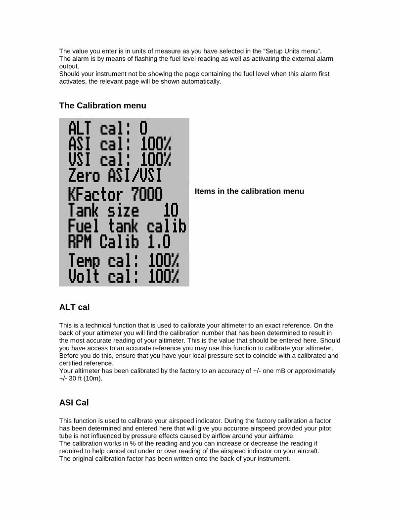
The Calibration menu
Items in the calibration menu
ALT cal This is a technical function that is used to calibrate your altimeter to an exact reference. On the back of your altimeter you will find the calibration number that has been determined to result in the most accurate reading of your altimeter. This is the value that should be entered here. Should you have access to an accurate reference you may use this function to calibrate your altimeter. Before you do this, ensure that you have your local pressure set to coincide with a calibrated and certified reference. Your altimeter has been calibrated by the factory to an accuracy of +/- one mB or approximately +/- 30 ft (10m).
ASI Cal This function is used to calibrate your airspeed indicator. During the factory calibration a factor has been determined and entered here that will give you accurate airspeed provided your pitot tube is not influenced by pressure effects caused by airflow around your airframe. The calibration works in % of the reading and you can increase or decrease the reading if required to help cancel out under or over reading of the airspeed indicator on your aircraft. The original calibration factor has been written onto the back of your instrument.
VSI cal This is a technical function that is used to calibrate your VSI to read exact rates of climb or decent. This function works as a percentage of initial reading. The default setting for this function is 100%. Increasing this value increases the VSI reading and decreasing the value decreases the reading. Suggested calibration method. After you have installed the instrument, perform a calibration flight. This should be done in very calm conditions. Turbulence and thermal activity will make accurate calibration impossible. Many areas have ideal conditions during early mornings or late afternoons. Place the instrument in “feet” units mode for ease of calibration. Take your aircraft to a few thousand feet above ground and start a glide with a low power setting. Take a stopwatch and when the glide is stable (stable VSI reading) start the stopwatch. Take note of your altimeter reading at the same time. Continue the stable glide for one minute exactly. After the minute has finished, take another reading of your altimeter. Example: VSI reading during stable glide: -400 ft/min Start altitude: 2500 ft. End altitude: 2050 ft. In the above example the VSI is under reading by about 12%. Set your VSI calibration to 112% to cancel out the error.
Zero ASI/VSI This setup allows your instrument to measure the zero airspeed reading of the airspeed sensor and set a calibration value internally for this. This is equivalent to some mechanical airspeed indicators that have an adjustment to set the needle to zero when the aircraft is not moving. You would use this function occasionally if you see an airspeed reading when the aircraft is at rest. This may be caused by aging of the built in pressure sensor or related electronics. When you perform this function, please make sure that no wind is blowing into the pitot tube as this would result in an incorrect internal calibration. This function also resets your VSI to zero. For maximum accuracy this should be performed on a wind still day. You may find that it is difficult to zero the VSI accurately if you perform this inside an aircraft hanger if there is any wind outside. This is because the buildings internal pressure will vary greatly with the winds airflow. The VSI is a very sensitive instrument.
KFactor The K-Factor is the number of pulses generated by the fuel flow sender for one liter of fuel. The dual range fuel flow sender supplied by MGL Avionics has a K-Factor of 7000 in the low flow mode (jet installed) and 1330 for the high flow mode (no jet installed). You can use the K-Factor to calibrate your fuel flow sender. The recommended procedure would be:
Fill your tank to an approximate known level (perhaps marked using a felt pen). Set the FF-3 to calculate fuel level from fuel flow (disable the fuel level sender using the menu function “LevelSend”). Set the fuel level to read 40 liters – the exact value is not important. Now fly of a quantity of fuel, perhaps 25 liters as example (very roughly – it does not need to be exact). Note the reading of the fuel level after you switch off the engine. Assume we are reading 28 liters now (we used 22 liters according to the instrument). Now fill the tank again, exactly to the previous level. Measure how much fuel you need to get to this previous level using a measuring jug. For example, assume we need 26 liters to get back to the previously marked fuel level. This means the fuel level should have been at 24 liters as we started with a value of 40 liters. This example would mean that our fuel flow sender is under reading by four liters as it has not measured the correct quantity of fuel. Now start adjusting the K-Factor so your tank level changes from 28 liters to 24 liters. You would adjust the K-factor down in this case (fewer pulses per liter of fuel). Using this calibration method you can get to very accurate fuel flow readings. The initial accuracy of fuel flow readings is dependant on the viscosity or type of fuel you use, added oils, installation and finally the temperature of the fuel. A good installation can achieve about a +/- 3% accuracy with as little as 1% error after calibration.
Tank size Enter the size of the fuel tank in your system. It is recommended to choose a size that is slightly less than actual size so you can compensate for sender inaccuracies and give you a measure of reserve fuel. You should perform this setting before you perform the fuel tank calibration. Enter your tank size even if you do not use a fuel level sender. If you use a fuel flow sender this value will be taken as being the maximum amount of fuel that you can enter for a calculated fuel level reading.
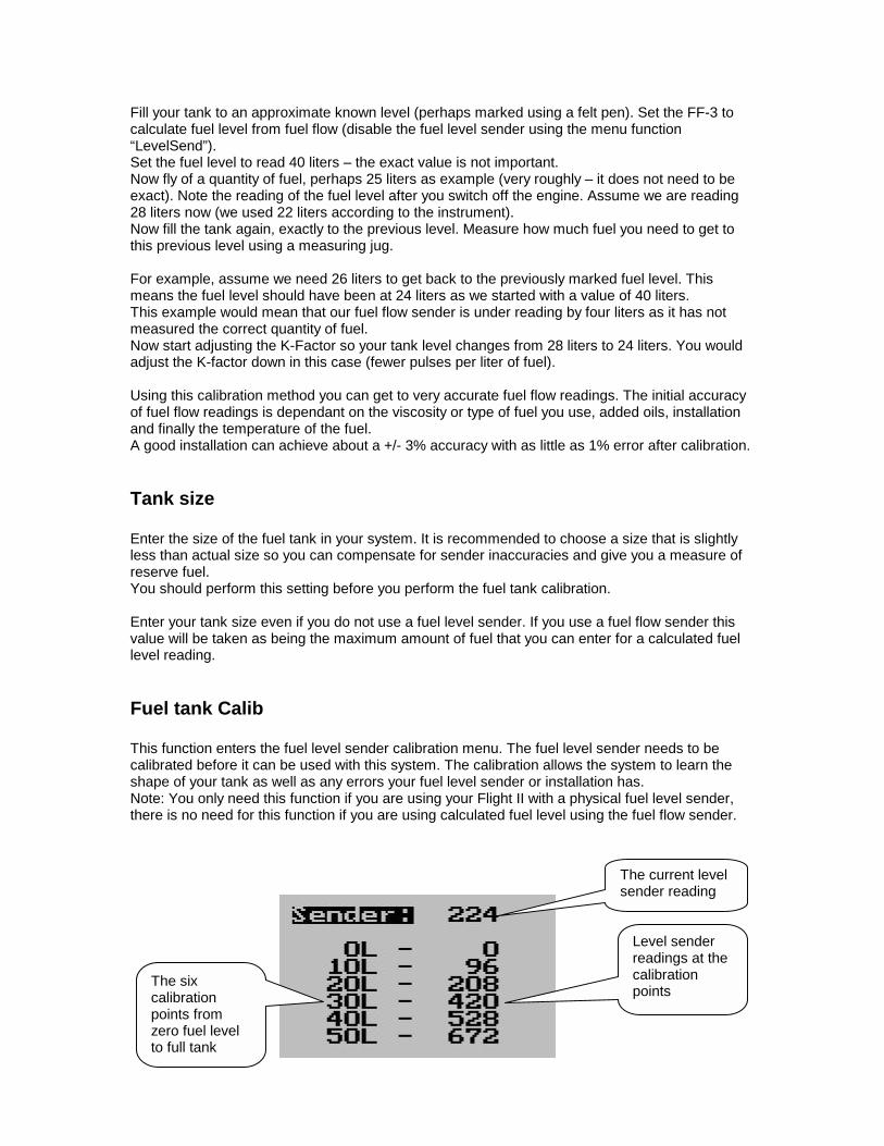
Fuel tank Calib This function enters the fuel level sender calibration menu. The fuel level sender needs to be calibrated before it can be used with this system. The calibration allows the system to learn the shape of your tank as well as any errors your fuel level sender or installation has. Note: You only need this function if you are using your Flight II with a physical fuel level sender, there is no need for this function if you are using calculated fuel level using the fuel flow sender.
The current level sender reading
Level sender readings at the calibration points
The six calibration points from zero fuel level to full tank
Performing the calibration procedure. Note: You start with an empty tank, you need a measuring jug or fueling device that has calibration marks and you need enough fuel to fully fill the tank. Regardless of your use of a fuel flow sender, you can install a fuel level sender into your fuel tank. These level senders are inexpensive and are available as after market replacement fittings from a car spares outlet. We recommend the senders available from VDO. Be aware that some makes of cheap level senders can prove troublesome, as the lever arms tend to be sticky. This prevents the floats from floating on the surface of the fuel at all times. As a consequence, this will lead to incorrect fuel level indication. Once you have installed a fuel level sender into your tank, make sure the float can travel all the way from empty to full position without hindrance of any kind. The calibration procedure should be carried out with your aircraft in flight attitude. This means you need to lift the tail if you have a tail-dragger or lift the nose wheel if you have a weightshift trike. You start the calibration procedure with an empty tank. We now start with the empty tank. Add five liters of fuel (our reserve quantity) using a suitable measure. Make sure the measure is suitably accurate. This is now the “level sender reading at 0 Lt” position. Move the highlight to this position and wait until the sender reading has stabilized (You will see the sender reading at the top line). This could take up to a minute so have patience. ENSURE THAT THE FLOAT IS NOT SUBMERGED AND IS FLOATING ON TOP OF THE FUEL LEVEL. Should this number not react to changes of your level sender position, then you have a problem. Please check your wiring according to the installation section of this manual. You should expect the number to change in the region of at least 20 to 60 counts per calibration position. If the number does not change with fuel level or only changes a very small amount – check your installation. Something is not right !!! If you see the number changing then everything is well. Once it has stabilized and the highlight is on the 0 Lt position, press the “Menu” key to transfer the reading from the sender to the calibration point. Now you are ready for the next step. Add the required amount of fuel to get to the next level (In our case 9 Lt – this is 20% tank capacity). Once done, wait for the reading to stabilize and press “Menu” again after you have moved the highlight to the “9 Lt” position. Proceed in a similar manner until you have reached the last calibration position at 100% tank capacity. You are done ! To finish your calibration, exit the calibration function by pressing the “Menu” key.
The instrument uses the 6 calibration points to work out a correction curve that takes into account the tolerances of your fuel level sender and the shape of your fuel tank. This results in an incredibly accurate and usable fuel level display that far exceeds that available from ordinary dial type gauges. Note:
The calibration positions may be edited by using the + and – keys. This allows you, in theory, to copy calibration settings from one instrument to another. We however recommend that you do go though the calibration procedure even if the two aircraft are identical in all respects. Tolerances do exist and the calibration cancels these out. Accurate fuel level displays are a vital safety factor for an aircraft and a very useful feature for peace of mind during cross county flights. Notes on Slope error Sender value is a value determined by the Flight II. It is used to calculate e.g. fuel level, fuel endurance estimate and current range estimate. The fuel tank setup sender value can either increase in value as fuel is added on decrease in value if fuel is added. This is dependant on the type of fuel level sender used. However should the second reading be larger than the first reading all readings will have to be larger than the previous reading. Likewise should the second reading be smaller than the first reading all readings will have to be smaller than the previous reading. If this is not the case the wording "Slope error" will be displayed. This could happen when fuel was removed instead of added between steps, no fuel was added between steps or when the fuel level sender was moved in the wrong direction e.g. moving the fuel level sender manually when it is not inserted in to the fuel tank. Should you get a slope error message determine the cause of the error. If you do not know the cause of your error it is best to start from scratch. It should be remembered that accuracy is the fuel tank calibration is extremely important to enable your Flight II to display the correct data. Adjusting calibration points manually You may want to set individual calibration points manually. For example you may find that your fuel level is over reading at a specific fuel level. Correcting the tank level reading for this area can be simply done by adjusting the calibration point. You can do this by moving the float level with your hands to the desired position and then performing the calibration as outlined above, or you can use the manual option. To activate manual change of the calibration points use the “+” and “-“ keys to highlight the “Sender: ….” Entry (top line of screen). Now press the “Select” key. You get:
When you are in manual mode, use the “+” and “-“ keys as before to select the point you want to calibrate. Then press the “Select” key. This allows you to change the value at the calibration point using the “+” and ‘-‘ keys. When you are done, press the Menu key again. To end the calibration, move the highlight past the last calibration point as before.
When you select any of the above points for manual editing, the display on the left shows and you can use the “+” and “-“ keys to adjust the value. Press “Menu” or “Select” when you are finished.
RPM Calib Enter the number of pulses per RPM. For engines with an uneven number of cylinders like three cylinder four stroke engines you can enter values containing fractions (usually 1.5 in this example). Most four stroke engines would generate one pulse for every two revolutions per cylinder. A four cylinder automotive four stroke engine would thus generate 2 pulses per revolution. A typical Rotax DCDI two stroke engine would generate 6 pulses per revolution. The well known Rotax 912/914 engines generate one pulse per revolution.
Temp Cal … This function is included to allow calibration of the ambient temperature probe. The calibration is entered as a percentage factor. Increasing this factor increases the temperature reading.
Volt Cal … This function is included to allow calibration of the supply voltage readout. The calibration is entered as a percentage factor. Increasing this factor increases the voltage reading.
Setting up the Flight II for the first time. After you have completed the physical installation of the Flight II, you need to setup the following items before you can proceed with flight testing: a) Select your mode of operation: We recommend to select automatic flight detection. For this to work correctly, you will need functioning airspeed indication and engine RPM display. Do not forget to set the take-off RPM limit in the “Setup Limits” menu. b) Select your units of measure This to you in the “Setup Units” menu. c) Set your alarm limits This you do in the “Setup Limits” menu. d) Set your rev counter pulses per RPM setting in the “calibration menu”. e) Select your fuel tank size in the calibration menu. f) In the operations setup menu, select if you are using a fuel flow sender, fuel level sender or both. g) If you are using a fuel level sender, you need to calibrate it in the “calibration menu”. h) Zero the ASI and VSI in the calibration menu. The above items will result in a functional installation, of course you will likely experiment with some settings as you get to know your instrument and refine your installation.
Technical specifications: Display temperature range (operational): -20 to +80 degrees C Supply voltage: +8 to +18V. +24/28V with optional pre regulator. Supply current: 30mA/50mA (backlight off/on) Altimeter range: -700ft to 40.000ft (45.000ft typical, not guaranteed) Altimeter resolution: 10ft at sea level. Measurement accuracy: +/- 1mB, +/- 30ft at sea level. Airspeed range: 16mph to 250mph Airspeed resolution: 1 mph Measurement accuracy: +/-1% at 85mph nominal. VSI range: Digital +/-10.000ft/min, Analog +/-1600 ft/min RPM range: 0-9999 RPM RPM input: A/C coupled, 8Vpp minimum signal amplitude, 50 VDC maximum with respect to negative supply terminal. Note: External transient protection required for signal sources that can contain high voltages. See suggested circuit in appendix. Voltmeter range: +8 to +25V DC Ambient temperature sender type: LM335 (National Semiconductor) Fuel flow input: DC coupled, voltage swing minimum 0-5V DC, 0-12V acceptable. Note: Some third party flow senders require pull up resistor to +12V supply rail. Airtalk link: Universal communications link supports flight log download and firmware updates. Weight: 210 grams. Warranty: MGL avionics warrants their products for a period of one year from date of purchase against faulty workmanship. Warranty is limited to the replacement of faulty components and includes the cost of labor. Shipping costs are for the account of the purchaser. Note for operation on supplies with inductive loads: Any operation of electronic instrumentation on power supplies that are subject to high voltages caused by operation of inductive loads (starter motors, solenoids, relays) are required to be fitted with suitable protection. All Smart Singles are guaranteed to withstand temporary over voltage up to 40V without additional protection. We recommend that measures are taken to prevent voltage transients in excess of this limit. MGL Avionics recommends the fitment of a fuse in line with a 33V transorb (available from MGL Avionics at low cost) to protect electronic instruments, radios and intercom systems. Only one such arrangement is required for a cluster of instruments. Please note that product warranty excludes damages caused by unprotected, unsuitable or incorrectly wired electrical supplies. This instrument is not certified by the FAA. Fitting of this instrument to certified aircraft is subject to the rules and conditions pertaining to such in your country. Please check with your local aviation authorities if in doubt. This instrument is intended for ultralight, microlight, homebuilt and experimental aircraft. Operation of this instrument is the sole responsibility of the pilot in command (PIC) of the aircraft. This person must be proficient and carry a valid and relevant pilots license. This person has to make him/herself familiar with the operation of this instrument and the effect of any possible
failure or malfunction. Under no circumstances does the manufacturer condone usage of this instrument for IFR flights.
Installing the Flight II
Alarm lampSuggested rating: 1Walso usable is a LED ifused with suitable dropping resistor
RedBlack Fuse
Powerswitch
Positive supply(+12V from battery)
Negative supply(airframe ground)
Suggested fuse rating:1.0 A slow blow
To other instruments
Cannon D-9connector
Fuel levelsender
Ambienttemperature
sender
Fuel flow sender
Red wire from flow senders
Blue wire from flowsender
Braid from flow sender
Brown
Yellow
Green
Red
Blue
Orange
Green
Cannon D-9 connectorpin mapping and cable colors
1 - ground - Black2 - fuel level - Orange3 - ambient temperature - Green4 - not used5 - Engine RPM - Blue6 - power (+12V) - Red7 - power out for fuel flow - Brown8 - fuel flow signal - Yellow9 - alarm output -White
Installing the Flight II is quite straight forward. Connect the supply terminals to your aircrafts power supply (you need a dropping resistor or pre-regulator for 24/28V systems). Install suitable power supply protection if you have a supply that can contain large voltage transients such as can be created by starter motors and solenoids. Ensure that the supply voltage will not drop below 8V during operation as this may result in incorrect altitude and airspeed readings. Connect the static port to a suitable static air pressure line. If you have a slow aircraft or an aircraft were the internal cabin pressure does not change during flight and is equivalent to the outside air pressure you may find that it is not required to connect a static port. For installations in typical ultralight aircraft pods, be aware of possible pressure changes inside the pod during flight caused by ram air or suction effects. This may lead to a false indication of altitude and/or airspeed. Often these effects are dependent on the current angle of attack of the airflow around your pod. You will need to install a suitable static port in these cases. Connect your pitot tube to the “pressure port”. Pitot tubes are found in a large variety in at your aircraft parts shop, in mail order catalogs or you can make your own. Contrary to popular belief, Pitot tubes are not carefully designed and calibrated but are simple orifices or tubes that get pointed in the direction that you are flying. The forward movement of the aircraft causes air to dam inside the pitot tube. This increases the pressure inside the tube. Most small aircraft such as ultralights or microlights do not require a connection to a static port. In these cases, simply leave the static port open. Ensure however that the static port does not receive pressurized air due to the forward movement of the aircraft. Be especially critical of your pod or panel if you do not use a static port. Any build up of a pressure differential due to ram air or suction can lead to large errors of the indicated airspeed. Static ports are usually mounted at a strategic position on the rear side of the aircraft fuselage for faster, pressurized aircraft. Suitable pitot tubes can be made from a short piece of hollow aluminium or copper piping. Length and diameter are not important. Ensure that the front of the pitot tube has a suitable chamfer if you use thick walled tubing or you may introduce a speed reading error if you have a faster aircraft. Example cross-section of thick walled pitot tube. Suitable connection hose for both pitot tube and static port can be obtained from a hardware store or even a pet shop. Good quality tubing is often used for fish tanks and it has just the right diameter.
Chamfer leading edges of pitot tube like this to reduce turbulence at the entry to the tube
Please note that this kind of tubing is not advised for pressurized aircraft. In this case you would need to obtain aircraft grade tubing of suitable diameter. You would also have to use hose clamps to fasten the hose onto the Stratomaster pitot and static ports. The Flight II allows you to calibrate the airspeed reading. This is done in the “ASI Cal” menu item. The main reason for this is to be able to remove errors introduced due to the airflow around your aircraft which may have an effect of your pitot tube pressure.
Rev counter pickup The above drawing shows a typical connection for a standard “old fashioned” contact breaker system. Most electronic ignition systems are very similar, the only difference is that the breaker has been replaced with a semiconductor switching device. Most electronic ignition modules have an output terminal intended for connection to a rev counter. This sample circuit suggests a 2200 ohm resistor (2K2) and a 20V zener diode. Note that the zener diode is a polarized device, install with the band marker as shown. This small circuit should be installed if older contact breaker ignition systems are used as it is possible for these systems to generate very high voltages over the contact breaker. This could potentially damage the instrument if no protection is used. The components can be obtained from any electronics parts shop and are very inexpensive. Most other sources of RPM pickup do not require any further protection. The Flight II RPM input is quite universally usable. For example, it is common to connect a hall-effect sensor using the +5V line to supply the sensor. A small magnet it then mounted on a shaft (for example rotor shaft of a helicopter) and the hall effect sensor switches every time the magnet passes the sensor. The Flight II needs a typical voltage swing of about 4 to 5.5V minimum to operate and the input is A/C coupled for easy installation. This means that the voltage signal may have a DC voltage superimposed without affecting the instrument. For example, if you have a signal that varies in voltage from 5V to 10V with every pulse, it can be used with the Flight II. For installations such as with the Rotax DCDI two-stroke engines, the rev counter input is simply connected to the grey rev counter wire from the engine. These engines produce six pulses per rev (set this up in the relevant menu item). Please note that is appears very common that many Rotax engines require a ballast resistor on the grey rev counter pickup wire. Some of these engines produce a very noisy signal without this ballast that can result in very unstable RPM readings. We have found a resistor of about 220 ohms to be a good value for most cases. Some engines may need as little as 100 ohms. This ballast resistor should in some cases also be used for the Rotax 912 engines. Most engines produce 0.5, 1 or 2 pulses per revolution. This needs to be setup in the “Calib” menu item. Please note: The 5V supply line is unprotected and intended only for the supply of hall-effect, optical or geartooth sensors. Connecting any voltages (such as the 12V supply) to this line will destroy the instrument. The 5V line may supply currents of up to 30mA. Should your sensor require greater currents you must supply it from another source.
Various pickup / sensor installation possibilities
Note: On Rotax DCDI ignition systems it may be required to install a ballast resistor as shown. A typical value is 220 ohms. Many installations can omit this. Typical hall effect sensor installation detects the passing of a magnet suitably fixed to prop flanges or shafts. The gear tooth sensor is a popular pickup used on the pre-rotation gear of a gyro plane. (rotor speed indication) The optical reflective pickup can provide a simple means of contactless RPM sensing in difficult installations.