Page 1
0
JOINT STOCK COMPANY ”SPORTINE AVIACIJA”
Pociunai, LT-4340 Prienai, Republic of Lithuania
FLIGHT MANUAL
FOR THE
LAK-17A SAILPLANE
(Issue No.2)
Model: LAK-17A
Serial Number:
Registration:
Date of Issue:
Pages identified by "Appr." are approved by the European Aviation
Safety Agency
Original date of approval: 21 April 2006
EASA TCDS No.EASA.A.083
This Manual should always be kept on board of the sailplane
This sailplane is to be operated in compliance with the regulatory
information and limitations contained herein.
Page 3
LAK-17A SAILPLANE FLIGHT MANUAL 0
Issue No.2 Author Date: 2004 04 05 Page 0.1
Rev. No.0 K.Juočas
0.1 Record of revisions
Any revision of the present manual, except actual weighing data, must be
recorded in the following table and in the case of approved sections endorsed by
the responsible airworthiness authority.
The new or amended text in the revised page will be indicated by a black
vertical line in the left hand margin, and the revision number and date will be
shown on the bottom left hand of the page.
Rev.
No.
Affected
Section
Affected
Pages
Date of
Issue
Approval Date of
approval
Date of
Insertion
Signature
Page 4
LAK-17A SAILPLANE FLIGHT MANUAL 0
Issue No.2 Author Date: 2004 04 05 Page 0.2
Rev. No.0 K.Juočas
Rev.
No.
Affected
Section
Affected
Pages
Date of
Issue
Approval Date of
approval
Date of
Insertion
Signature
Page 5
LAK-17A SAILPLANE FLIGHT MANUAL 0
Issue No.2 Author Date: 2004 04 05 Page 0.3
Rev. No.0 K.Juočas
0.2 List of effective pages
Section Page Date of Issue Section Page Date of Issue
0 0.1 2004 04 05 5 5.1 2004 04 05
0.2 2004 04 05 Appr.5.2 2004 04 05
0.3 2004 04 05 Appr.5.3 2004 04 05
0.4 2004 04 05 Appr.5.4 2004 04 05
1 1.1 2004 04 05 6 6.1 2004 04 05
1.2 2004 04 05 6.2 2004 04 05
1.3 2004 04 05 6.3 2004 04 05
1.4 2004 04 05 6.4 2004 04 05
1.5 2004 04 05 6.5 2004 04 05
1.6 2004 04 05 6.6 2004 04 05
2 2.1 2004 04 05 6.7 2004 04 05
Appr.2.2 2004 04 05 6.8 2004 04 05
Appr.2.3 2004 04 05 6.9 2004 04 05
Appr.2.4 2004 04 05 6.10 2004 04 05
Appr.2.5 2004 04 05 6.11 2004 04 05
Appr.2.6 2004 04 05 6.12 2004 04 05
Appr.2.7 2004 04 05 6.13 2004 04 05
Appr.2.8 2004 04 05 6.14 2004 04 05
Appr.2.9 2004 04 05
3 3.1 2004 04 05 7 7.1 2004 04 05
Appr.3.2 2004 04 05 7.2 2004 04 05
Appr.3.3 2004 04 05 7.3 2004 04 05
Appr.3.4 2004 04 05 7.4 2004 04 05
Appr.3.5 2004 04 05 7.5 2004 04 05
4 4.1 2004 04 05 7.6 2004 04 05
Appr.4.2 2004 04 05 7.7 2004 04 05
Appr.4.3 2004 04 05 8 8.1 2004 04 05
Appr.4.4 2004 04 05 8.2 2004 04 05
Appr.4.5 2004 04 05 8.3 2004 04 05
Appr.4.6 2004 04 05 8.4 2004 04 05
Appr.4.7 2004 04 05 9 9.1 2004 04 05
Appr.4.8 2004 04 05
Appr.4.9 2004 04 05
Appr.4.10 2004 04 05
Appr.4.11 2004 04 05
Page 6
LAK-17A SAILPLANE FLIGHT MANUAL 0
Issue No.2 Author Date: 2004 04 05 Page 0.4
Rev. No.0 K.Juočas
0.3 Table of contents
Section
GENERAL (a non-approved section) 1
LIMITATIONS (an approved section) 2
EMERGENCY PROCEDURES (an approved section) 3
NORMAL PROCEDURES (an approved section) 4
PERFORMANCE (a partly approved section) 5
WEIGHT AND BALANCE (a non-approved section) 6
SAILPLANE AND SYSTEMS DESCRIPTION 7
(a non-approved section)
SAILPLANE HANDLING, CARE AND MAINTENANCE 8
(a non-approved section)
SUPPLEMENTS (a non-approved section) 9
Page 7
LAK-17A SAILPLANE FLIGHT MANUAL 0
Issue No.2 Author Date: 2004 04 05 Page 1.1
Rev. No.0 K.Juočas
Section 1 GENERAL
1.1 Introduction
1.2 Certification basis
1.3 Warnings, cautions and notes
1.4 Descriptive data
1.5 Three view drawing
1.6 Abbreviations
1.7 Unit conversions
Page 8
LAK-17A SAILPLANE FLIGHT MANUAL 0
Issue No.2 Author Date: 2004 04 05 Page 1.2
Rev. No.0 K.Juočas
1.1 Introduction
This sailplane flight manual has been prepared to provide pilots and
instructors with information for the safe and efficient operation of the LAK-
17A sailplane.
This manual includes the material required to be furnished to the pilot by
JAR 22. It also contains supplemental data supplied by the sailplane
manufacturer.
1.2 Certification basis
This type of sailplane has been approved by the Lithuanian Directorate of
Civil Aviation in accordance with: Airworthiness Requirements: JAR 22
Sailplanes and Powered Sailplanes, Change 5, Issued 28 October 1995.
The Type Certificate Number 03 has been issued on 20 August 1999.
Category of Airworthiness: Utility.
1.3 Warnings, cautions and notes
The following definitions apply to warnings, cautions and notes used in the
flight manual:
Page 9
LAK-17A SAILPLANE FLIGHT MANUAL 0
Issue No.2 Author Date: 2004 04 05 Page 1.3
Rev. No.0 K.Juočas
Warning: Means that the non-observation of the corresponding
procedure leads to an immediate or important
degradation of the flight safety.
Caution: Means that the non-observation of the corresponding
procedure leads to a minor or to a more or less long
term degradation of the flight safety.
Note: Draws the attention on any special item not directly
related to safety but which is important or unusual.
1.4 Descriptive data
The LAK-17A is a new generation of FAI 15m - 18m class sailplane
designed according to JAR-22 category “U” specifications. It is a midwing
glider with flaps, T-tail, retractable main landing gear and 180 litre water
ballast.
The sailplane is made of hybrid composite materials (Kevlar, carbon,
glass fibre). The wing spar is made of modern carbon rods GRAPHLITE
SM315 and has a double T section. The weight of each wing panel is about
60kg. The airbrakes are situated on the upper surfaces only. The wing airfoil
is LAP 92-130/15 and it passes into LAP 92-150/15 at the tip.
The cockpit is of monocoque construction. The on-ground adjustable
seat back position and in-flight adjustable angle of a seat back together with
optimally arranged controls offer notable comfort on the long flights. The one-
piece Plexiglas canopy hinges forward. On the left side there is a sliding
window for additional ventilation. The instrument panel folds up together with
canopy.
Page 10
LAK-17A SAILPLANE FLIGHT MANUAL 0
Issue No.2 Author Date: 2004 04 05 Page 1.4
Rev. No.0 K.Juočas
The retractable landing gear with shock absorber has a 5.00-5 6 ply
tire. The mechanical main wheel brake is actuated via the handle on the
control stick. The rudder pedals are adjustable in flight. All controls,
including the water ballast system, hook up semi-automatically. Towing
hooks are mounted: near the main landing gear (C.G. / winch / auto-tow
hook) and/or in front of the pilot cockpit at the bulkhead (aero tow hook).
Both towing hooks are operated by the same handle. The wings incorporate
fork-type spar connection, joined with two pins.
The horizontal tail (stabilizer and elevator) of the LAK-17A provides
stable and responsive pitch characteristics. The elevator hooks up
automatically during assembly.
The glider is fitted with a fin ballast tank (capacity 8 litre) in order to
adjust the optimum C.G. position. The wing water ballast is filled in and
poured out through the holes at the bottom of the wings.
The antenna is mounted in the vertical fin.
Technical data:
Wing span, m 15.0 18.0
Fuselage length, m 6.53 6.53
Height, m 1.29 1.29
Max gross weight, kg 500 500
Mean aerodynamic chord, m 0.626 0.598
Wing area, m2 9.06 9.8
Wing loading, kg/m2:
- minimum 31.5 30.1
- maximum 55 51
Page 11
LAK-17A SAILPLANE FLIGHT MANUAL 0
Issue No.2 Author Date: 2004 04 05 Page 1.5
Rev. No.0 K.Juočas
1.5 Three view drawing
15 m
15 m (winglet)
18 m
18 m (winglet)
Page 12
LAK-17A SAILPLANE FLIGHT MANUAL 0
Issue No.2 Author Date: 2004 04 05 Page 1.6
Rev. No.0 K.Juočas
1.6 Abbreviations
CAS - calibrated airspeed means indicated airspeed of a sailplane,
corrected for position (due to position of pressure ports on
sailplane) and instrument error. Calibrated airspeed is equal to
true airspeed in standard atmosphere at sea level.
C.G. - centre of gravity.
daN - decanewton.
h - hour.
IAS - indicated airspeed means the speed of a sailplane as shown on
its pitot – static aircraft indicator and is uncorrected for the
system error.
m - meter.
kg - kilogram.
km - kilometre.
s - second.
1.7 Unit conversions
1 bar = 14.5 pounds per square inch (psi);
1 decanewton (daN) = 2.25 pounds force;
1 kilogram (kg) = 2.2 pounds (lbs);
1 metre (m) = 39.4 inches (in.) = 3.28 feet (ft.);
1 millimetre (mm) = 0.0394 inches (in.);
1 litre = 0.2642 U.S. gal;
1 square meter (m2) = 10.764 sq.ft;
1 kg/m2 = 0.204 lbs/sq.ft;
1 m/s = 1.944 knots (kts);
1 km/h = 0.5396 kts.
Page 13
LAK-17A SAILPLANE FLIGHT MANUAL 0
Issue No.2 Author Date: 2004 04 05 Page 2.1
Rev. No.0 K.Juočas
Section 2 LIMITATIONS
2.1 Introduction
2.2 Airspeed
2.3 Airspeed indicator markings
2.4 Weight
2.5 Centre of gravity
2.6 Approved manoeuvres
2.7 Manoeuvring load factors
2.8 Kinds of operation
2.9 Minimum equipment
2.10 Aerotow, winch and auto-tow launching
2.11 Other limitations
2.12 Limitation placards
Page 14
LAK-17A SAILPLANE FLIGHT MANUAL 0
Issue No.2 Author Date: 2004 04 05 Page 2.2
Rev. No.0 K.Juočas Appr.
2.1 Introduction
Section 2 includes operation limitations, instrument markings and placards
necessary for safe operation of the LAK-17A sailplane, standard systems and
standard equipment. The limitations included in this section have been approved
by the Lithuanian Civil Aviation Administration. Compliance with these
limitations is mandatory.
2.2 Airspeed
Airspeed limitations and their operational significance are shown below:
Warning: At higher altitudes the true airspeed is higher than the
indicated airspeed, so VNE is reduced with altitude.
Speed IAS, km/h Remarks
15m and 18m
VNE
Never exceed speed
275
Do not exceed this speed in any
operation and do not use more
than 1/3 of control deflection:
from 0 m to 4000 m
260 up to 5000 m
245 up to 6000 m
220 up to 8000 m
195 up to 10000 m
VRA Rough air speed 205 Do not exceed this speed except
in smooth air and then only with
caution. Rough air is in lee
wave rotor, thunderclouds, etc.
Page 15
LAK-17A SAILPLANE FLIGHT MANUAL 0
Issue No.2 Author Date: 2004 04 05 Page 2.3
Rev. No.0 K.Juočas Appr.
Speed IAS, km/h Remarks
15m and 18m
VA Manoeuvring speed 205 Do not make full or abrupt
control movement above this
speed, because under certain
conditions the sailplane may be
over-stressed by full control
movement.
VFE Maximum Flap
Extended speed flap
setting:
-1 up to 0
+1 up to L
275
160
Do not exceed these speeds with
the given flap setting.
VW Maximum winch
and auto-tow
launch speed
140 Do not exceed this speed during
winch or auto-tow launching.
VT Maximum aero
towing speed
160 Do not exceed this speed during
aero towing.
VLO Maximum landing
gear operations
speed
205 Do not extend or retract the
landing gear above this speed.
Page 16
LAK-17A SAILPLANE FLIGHT MANUAL 0
Issue No.2 Author Date: 2004 04 05 Page 2.4
Rev. No.0 K.Juočas Appr.
2.3 Airspeed indicator markings
Airspeed indicator markings and their colour code significance are shown
below:
Marking IAS value or range Significance
White Arc 90 - 160 km/h Positive Flaps Operating Range: Lower
limit is 1.1 VSO in landing configuration
at maximum weight. Upper limit is
maximum speed permissible with flaps
extended positive.
Green Arc 100 - 205 km/h Normal Operating Range: Lower limit is
1.1 VS1 at maximum weight and most
forward C.G. with flaps neutral. Upper
limit is rough air speed.
Yellow Arc 205 - 275 km/h Manoeuvres must be conducted with
caution and only in smooth air.
Red Line 275 km/h Maximum speed for all operations.
Yellow
Triangle
90 km/h Approach speed at maximum weight
without water ballast.
Page 17
LAK-17A SAILPLANE FLIGHT MANUAL 0
Issue No.2 Author Date: 2004 04 05 Page 2.5
Rev. No.0 K.Juočas Appr.
2.4 Weight
Maximum take-off mass:
- with water ballast …………………. 500 kg
- without water ballast for: 15m….... 355 kg
18m…... 360 kg
Maximum landing mass….…….……………………. 500 kg
Note: When landing on a rough surface, before landing always
dump all water ballast.
Minimum pilot and parachute weight……………….. 70 kg
Maximum pilot and parachute weight………………. 110 kg
Maximum mass of all non-lifting parts……………… 233 kg
Maximum mass in baggage area ….………..….……. 7 kg
Caution: Heavy pieces of baggage must be secured to the baggage
compartment floor.
2.5 Centre of gravity
Position of C.G. in flight:
- front limit 182 mm aft of wing root rib leading edge.
- rear limit 305 mm aft of wing root rib leading edge.
Warning: The sailplane may be safely operated only when loaded in the
range defined in Section 6 of this manual.
Page 18
LAK-17A SAILPLANE FLIGHT MANUAL 0
Issue No.2 Author Date: 2004 04 05 Page 2.6
Rev. No.0 K.Juočas Appr.
2.6 Approved manoeuvres
This sailplane is certified for normal gliding in the "Utility" category according
to JAR-22. Aerobatic manoeuvres are not permitted.
2.7 Manoeuvring load factors
Limit load factors are:
- for VA = 205 km/h airspeed +5.3 / -2.65;
- for VNE = 275 km/h airspeed +4.0 / -1.5;
- for VNE = 275 km/h, air brakes extended +3.5 / 0;
- for VF = 160 km/h, flap position +1;+2; L +4;
2.8 Kinds of operation
Flights must be conducted under Day / VFR conditions.
Where permitted by national regulations, cloud flying may be conducted but
only with 15m wings (including 15m winglets) and without water ballast.
Consider the different national legal requirements (for e.g. additional
equipment) for cloud flying (see also paragraph 2.9).
Aerobatics manoeuvres are not permitted.
2.9 Minimum equipment
As minimum equipment only the instruments and equipment specified here and
in the equipment list (see Maintenance Manual Section 2) are admissible:
- airspeed indicator, scale 50-300 km/h, with range markings (see
Section 2.3);
- altimeter with altitude corrector and fine range pointer;
- four part symmetrical seat harness;
- transceiver;
- power supply (fin battery);
- outside air temperature (OAT) gauge (if water ballast is carried);
- emergency locator transmitter (ELT) *.
* - if required by National regulations.
Page 19
LAK-17A SAILPLANE FLIGHT MANUAL 0
Issue No.2 Author Date: 2004 04 05 Page 2.7
Rev. No.0 K.Juočas Appr.
For cloud flying the following additional equipment is required:
- variometer;
- magnetic compass compensated in the sailplane;
- turn and bank indicator, non-icing;
- transceiver;
- parachute, automatic or manual opening type;
- thermometer for outside air;
- non-icing airspeed system.
The minimum equipment must correspond with national regulations.
2.10 Aerotow, winch and auto-tow launching
The maximum launch speeds are:
Aerotow 160 km/h,
Winch / Auto-tow launch 140 km/h.
For all of the above launching methods a weak link of 650 daN must be used in
the launch cable or towrope.
For aerotow, the towrope must be at least 20m long.
Warning: For winch or auto tow launch only C.G. hook can be used.
Warning: Aerotow launches are only allowed at the aerotow hook.
Page 20
LAK-17A SAILPLANE FLIGHT MANUAL 0
Issue No.2 Author Date: 2004 04 05 Page 2.8
Rev. No.0 K.Juočas Appr.
2.11 Other limitations
Crosswinds:
The maximum crosswind component according to the airworthiness
requirements for take-off and landing is 4.16 m/s (15 km/h).
Water Ballast
Filling of the wing water ballast tanks must result in a symmetrical loading
condition only. After filling, balance the wings by dumping enough water from
the heavy wing to achieve lateral balance. Flight with leaking water ballast is
not permitted as this may result in asymmetrical loading. Flight with water
ballast must be conducted at an OAT greater than 1°C (34 °F).
Warning: Maximum take-off weight must not exceeded.
2.12 Limitation placards
The following limitation placards are installed:
- the air speed data and loading placard installed in a cockpit.
LAK-17A 15m/18m - AIR SPEED DATA AND LOADING PLACARD
Speed IAS: km/h kts Masses and loads kg lbs
Never exceed VNE 275 148 Empty mass 245/250 540/551
Rough air VRA 205 110 Max. mass with water ballast 500 1102
Manoeuvring VA 205 110 Maximum cockpit load 110 242
Aerotow VT 160 86 Minimum cockpit load 70 154
Winch-launch VW 140 75 Recommended weak link 650 daN 1460 lbs
Landing gear oper. VL 205 110
Aerobatic manoeuvres are not permitted
- the baggage limitation placard installed in a baggage compartment.
Max baggage weight 7 kg
- the main wheel tyre pressure placard installed on a landing gear door.
Pressure in a main wheel tyre
from 2,3 to 2,5 bar
Page 21
LAK-17A SAILPLANE FLIGHT MANUAL 0
Issue No.2 Author Date: 2004 04 05 Page 2.9
Rev. No.0 K.Juočas Appr.
- the tail wheel tyre pressure placard installed next to the tail wheel.
Pressure in a tail wheel tyre
from 1,8 to 2,0 bar
The high altitude flights limitation placard is shown in section 4.5.7.
Page 22
LAK-17A SAILPLANE FLIGHT MANUAL 0
Issue No.2 Author Date: 2004 04 05 Page 3.1
Rev. No.0 K.Juočas
Section 3 EMERGENCY PROCEDURES
3.1 Introduction
3.2 Canopy jettison
3.3 Bailing out
3.4 Stall recovery
3.5 Spin recovery
3.6 Spiral dive recovery
3.7 Recovery from unintentional cloud flying
3.8 Flight with asymmetric water ballast
3.9 Emergency wheel up landing
3.10 Ground loop
3.11 Ditching landing on water
Page 23
LAK-17A SAILPLANE FLIGHT MANUAL 0
Issue No.2 Author Date: 2004 04 05 Page 3.2
Rev. No.0 K.Juočas Appr.
3.1 Introduction
Section 3 provides a checklist and explanations for coping with emergencies
that may occur. Emergency situations can be minimized by proper pre-flight
inspections and maintenance.
3.2 Canopy jettison
The following steps accomplish canopy jettison:
1. Pull the red canopy jettison handle aft to the limit of its travel.
2. Release the handle.
The canopy jettison handle is located on the instrument panel and has an icon
describing its function. A compression spring in the canopy hinge pushes the
canopy upward and allows the airflow to lift the front of the canopy upward
while the rear of the frame pivots about a small lip on the fuselage. This system
is designed to lift the canopy up and away from the flying glider to allow the
pilot a quick bail out from the cockpit.
If necessary, you have to push the canopy upwards with both hands on the
Plexiglas.
Warning: The red handle of the spring-type mechanism on the canopy
hinge must be in the unlocked (working) position.
3.3 Bailing out
First jettison the canopy then unlock the safety harness and bail out. The low
walls of the cockpit allow for a quick push off exit.
It is recommended that bail out procedures be practiced on the ground at the
beginning of each flying season.
Page 24
LAK-17A SAILPLANE FLIGHT MANUAL 0
Issue No.2 Author Date: 2004 04 05 Page 3.3
Rev. No.0 K.Juočas Appr.
3.4 Stall recovery
Stall recovery is accomplished by easing the stick forward and if necessary
picking up a dropping wing with sufficient opposite rudder.
3.5 Spin recovery
Apply full opposite rudder against the direction of rotation and ease the stick
forward until the rotation stops. At aft C.G. positions the glider may move
temporarily to a nose up position making it necessary to apply full stick
forward. As the rotation stops centralize the controls and carefully pull out of
the dive. The ailerons should be kept neutral during spin recovery.
Recovery from unintentional spins should be done immediately.
Caution: Altitude loss due an incipient spin from straight flight with
prompt recovery is 30 m, increasing to 60 m from circling flight
and 60 m to 110 m with airbrakes extended. Maximum speed
during recovery is 200 km/h.
3.6 Spiral dive recovery
To recover from a spiral dive, apply rudder and aileron in the direction opposite
to the spiral dive rotation and carefully pull out of the dive.
Page 25
LAK-17A SAILPLANE FLIGHT MANUAL 0
Issue No.2 Author Date: 2004 04 05 Page 3.4
Rev. No.0 K.Juočas Appr.
3.7 Recovery from unintentional cloud flying
At speeds below 205 km/h, extend the dive brakes fully. At higher speeds, up to
VNE, pull out the dive brakes very carefully and expect high aerodynamic forces
and g-loads. Enter the descent and fly normally until leaving the cloud. When
clear of the cloud, retract the dive brakes and reduce speed. Spins are not to be
used to lose altitude.
3.8 Flight with asymmetrical water ballast
If you suspect that the water ballast is dumping asymmetrically, you should
close the dump valves immediately to avoid greater asymmetry. Asymmetry can
be verified by the necessary aileron deflection in straight flight at low airspeeds.
When flying with asymmetric water ballast you must increase your airspeed,
especially in turns, so that you can avoid stall at all costs. Should the aircraft
enter a spin under these conditions, aggressive stick forward spin recovery will
be necessary. Fly the landing pattern and touch down approximately 10 km/h
faster than normal and after touch down attempt to control the bank angle to
avoid the heavy wing from touching the ground too early.
3.9 Emergency wheel up landing
An emergency wheel up landing is not recommended since the absorption
capability of the fuselage is much smaller than that of the landing gear. If the
landing gear cannot be extended the landing touchdown should be at slow
speed.
Page 26
LAK-17A SAILPLANE FLIGHT MANUAL 0
Issue No.2 Author Date: 2004 04 05 Page 3.5
Rev. No.0 K.Juočas Appr.
3.10 Ground loop
If there is a risk of overshooting the landing area, after touchdown an intentional
ground loop may be initiated by forcing a wing tip to the ground and at the same
time you should PUSH the stick forward to lighten the load on the tail wheel
and apply the opposite rudder.
3.11 Ditching landing on water
Our experience shows that in ditching the cockpit area likely will be forced
downward under water. Therefore, an emergency landing on water is
recommended only with the canopy closed, landing gear extended and then only
as a last resort.
Page 27
LAK-17A SAILPLANE FLIGHT MANUAL 0
Issue No.2 Author Date: 2004 04 05 Page 4.1
Rev. No.0 K.Juočas
Section 4
NORMAL PROCEDURES
4.1 Introduction
4.2 Rigging and de-rigging
4.3 Daily inspections
4.4 Pre-flight inspection
4.5 Normal procedures and recommended speeds
4.5.1 Aerotow launch
4.5.2 Winch- launch or auto tow
4.5.3 Free flight
4.5.4 Low speed flight and stalling behaviour
4.5.5 Approach and landing
4.5.6 Flight with water ballast
4.5.7 High altitude flights
4.5.8 Flight in rain
Page 28
LAK-17A SAILPLANE FLIGHT MANUAL 0
Issue No.2 Author Date: 2004 04 05 Page 4.2
Rev. No.0 K.Juočas Appr.
4.1 Introduction
This section provides checklists and explanations of procedures for conducting
normal operating procedures. Normal procedures associated with optional
equipment can be found in Section 9.
4.2 Rigging and de-rigging
The following procedures are recommended for rigging and de-rigging the
LAK-17A sailplane:
1. Clean and lubricate all pins, bushings and control connections. Inspect the
pins and bushings for burrs and gouges.
2. Support the fuselage and keep it upright, open the canopy and extend the
landing gear. Place the control stick in the centre of its travel. Position the
dive brake handle near its most forward position, flaps handle in “-1”
position. Put the water ballast control in the forward, closed position.
3. Be sure the dive brake system in the wings is not locked. Remove any
supports or locks over the ailerons.
4. Insert the left wing spar fork into the fuselage. As the wing root approaches
the fuselage, look to be sure the automatic hook-ups for the aileron, flaps
and dive brake properly engage. Look to see if the water ballast control is
engaging correctly. After the wing is pushed into position, support the wing
tip.
Note: It’s not allowed to rig or de-rig wings with winglets or 18m wingtips
with or without winglets installed.
Page 29
LAK-17A SAILPLANE FLIGHT MANUAL 0
Issue No.2 Author Date: 2004 04 05 Page 4.3
Rev. No.0 K.Juočas Appr.
5. Insert the right wing spar into the fuselage. As the wing root approaches the
fuselage look to be sure the automatic hook-ups for the aileron, flap and dive
brake properly engage. Look to see if the water ballast control is engaging
correctly. Line up the main pin bushings. Insert both spar pins fully. Lock
the main wing pin handles.
Warning: Lock the main wing pin handles with fixing studs.
6. Install winglets or wing tips and lock.
7. Caution: Insert battery into vertical tail, connect to electric system and
check operation.
Slide the stabilizer onto the drive pins and look to make sure the automatic
hook-ups for the elevator properly engage. Push the stabilizer all the way
onto the drive pins. Screw the locking bolt in and make sure, that the bolt is
fixed. After removing the assembly tool, place a piece of glider tape over the
locking bolt.
Warning: Pull out the locking pin before unscrewing horizontal
stabilizer connection bolt.
8. Apply sealing tape to the wing/fuselage gaps.
9. Perform a positive control check of all controls.
10. If water ballast is necessary, fill each wing tank according to the loading
chart (see Section 6) and confirm symmetrical loading by balancing at the
wing tip. A light coating of waterproof grease applied to the dump valve seat
will help insure the valve is leak free.
Warning: Allow wing tanks to vent while filling. Do not fill with
pressure exceeding 1 psi / 0.06 bar as the wing shell could be
damaged. Check for proper dump valve operation prior to
flight. Do not exceed the maximum gross weight.
Page 30
LAK-17A SAILPLANE FLIGHT MANUAL 0
Issue No.2 Author Date: 2004 04 05 Page 4.4
Rev. No.0 K.Juočas Appr.
11. Install total energy probe and temporary equipment (barographs etc.).
12. Perform Daily Inspection.
13. De-rigging follows the reverse order of rigging. Confirm that water ballast
has been dumped before de-rigging. Also see Maintenance Manual Section 3.
Note: Remove the stabilizer before removing the wings.
4.3 Daily Inspections
Prior the first flight of the day the glider must receive a daily inspection. As a
minimum check the following items. If any problems are found they must be
corrected before flying.
1. Check the fore part of the sailplane fuselage.
2. Check in the pilot cockpit:
- the pilot cockpit canopy glass;
- operation of pilot cockpit canopy lock, canopy jettison system;
- wings connection pins fastening;
- operation of towing hook(s);
- operation of water ballast system;
- operation of control systems of ailerons, flaps, elevator, rudder and
airbrakes;
- operation of pilot cockpit ventilation control system;
- operation of the trimmer;
- operation of flight instruments;
- radio communication;
- safety belts.
3. Check main wheel tyre and operation of wheel brake.
Page 31
LAK-17A SAILPLANE FLIGHT MANUAL 0
Issue No.2 Author Date: 2004 04 05 Page 4.5
Rev. No.0 K.Juočas Appr.
4. Check the left wing:
- upper and lower wing surfaces;
- leading edge;
- upper and lower surfaces of ailerons and flaps;
- deflections of ailerons and flaps and their clearances;
- airbrakes for proper function and locking;
- fixing of ailerons and flaps attachment to wing;
- clearance in respect of the fuselage;
- winglets or wing tips installed and locked.
5. Check the function of the control systems (of the aileron, flap, airbrake), their
connections to corresponding control systems in the fuselage.
6. Check the fuselage surface.
7. Check a stabilizer, elevator and rudder:
- surfaces;
- deflections and clearances of controls;
- fixing of joint of the stabilizer attachment to the fin;
- clearance of the stabilizer with respect to the fin.
8. Check the right wing (same as for the left wing according to i.4).
Also see Maintenance Manual Section 3.
Caution: After a hard landing or if high loads have been experienced a
complete inspection according to the Maintenance Manual Section
5.5 must be performed. Contact the manufacture for assistance as
required.
Page 32
LAK-17A SAILPLANE FLIGHT MANUAL 0
Issue No.2 Author Date: 2004 04 05 Page 4.6
Rev. No.0 K.Juočas Appr.
4.4 Pre-flight inspection
1. Main spar pins installed and locked.
2. Controls checked for operation and freedom of movement.
3. Lead or water ballast for underweight pilot installed or filled.
4. Tail dolly removed.
5. Pilot safety harness connected and properly adjusted/tightened.
6. Seat back and rudder pedals adjusted.
7. All control knobs within reach.
8. Water ballast checked, dump valve closed and vents open.
9. Airbrakes closed and locked.
10. Trim set to take-off position.
11. Flaps set to take-off position.
12. Check wheel brake.
13. Altimeter set correctly.
14. Check direction of wind component.
15. Close and lock canopy.
Page 33
LAK-17A SAILPLANE FLIGHT MANUAL 0
Issue No.2 Author Date: 2004 04 05 Page 4.7
Rev. No.0 K.Juočas Appr.
4.5 Normal procedures and recommended speeds
Normal flight operation procedures and the corresponding recommended air
speeds are as follows.
4.5.1 Aerotow launch
Flaps should be set at take off position “+1” when C.G. is at rearmost position
and “+2” at middle and foremost position of C.G. Trim should be set forward of
neutral.
Warning: Aerotow launches are only allowed at the aerotow hook.
Warning: when water tanks are partially filled, keep wings horizontal before
take off to avoid uneven water distribution.
Weak link in tow cable max 650 daN. Use wheel brake during tightening of tow
cable to avoid rolling over tow cable.
Minimum aero tow speed:
without water ballast……100 km/h.
with water ballast……….120 km/h.
4.5.2 Winch- launch or auto tow
Trim should be set forward of neutral. Set flaps to “+1” at rearmost position of
C.G. and “+2” at middle and foremost position of C.G.
Warning: for winch or auto tow launch only C.G. hook can be used.
Warning: it is prohibited to use the aerotow hook for winch or auto-tow
launches.
Warning: when water tanks are partially filled, keep wings horizontal before
take off to avoid uneven water distribution.
Weak link in tow cable max 650 daN. Use wheel brake during tightening of tow
cable to avoid rolling over tow cable. Pronounced forward stick pressure is
required during transition arc.
Page 34
LAK-17A SAILPLANE FLIGHT MANUAL 0
Issue No.2 Author Date: 2004 04 05 Page 4.8
Rev. No.0 K.Juočas Appr.
Minimum winch launch / auto tow speed:
without water ballast……100 km/h.
with water ballast……….120 km/h.
4.5.3 Free flight
Circling flight (thermlaling) with flaps position +2, stick forces to zero. Best
glide angle between 95 and 105km/h.
High speed flight up to 275 km/h :
- position flaps at “0” or “-1” according to the speed;
- due to flap control forces, flaps position “+2” may not be set
above 160km/h.
Recommended flaps positions:
Flap position Speed, km/h
without water ballast with maximum take off weight
L landing landing
+2 ≤ 90 ≤ 110
+1 90 - 120 110 - 150
0 110 - 180 140 - 220
-1 150 - 275 190 - 275
Page 35
LAK-17A SAILPLANE FLIGHT MANUAL 0
Issue No.2 Author Date: 2004 04 05 Page 4.9
Rev. No.0 K.Juočas Appr.
4.5.4 Low speed flight and stalling behaviour
The LAK-17A behaves normally in slow and stalled flight.
With a forward C.G. position there is no stall
warning, but the stall characteristics are very
gentle and large aileron deflections can be
applied without dropping a wing.
At rearward C.G. positions airflow separation over the fuselage results in
buffeting and gives a warning of an impending stall at a speed 1 - 2 km/h above
the stall speed. Full and sudden aileron or rudder deflections will result in a
spiral dive, spin entry or slide slip depending on the C.G. position.
Caution: Altitude loss due to an incipient spin from straight flight with
prompt recovery is approximately 30 m, increasing to 60 m from
circling flight.
4.5.5 Approach and landing
Recommended flaps position “L” (landing). In light winds and without water
ballast the approach to landing should be flown at about 90 km/h. Stronger
winds require increased airspeeds. The very effective dive brakes make a short
landing possible; however, do not approach too slowly with fully extended dive
brakes as the aircraft may drop during the flare out. The LAK-17A should touch
down on the main and tail wheel. The main wheel landing brake can then be
applied for a shortened ground roll.
In side - slip with airbrakes extended there will be vibration of the sailplane. The
control-stick should be in aft position.
Due to side - slip rudder back pressure is possible.
Page 36
LAK-17A SAILPLANE FLIGHT MANUAL 0
Issue No.2 Author Date: 2004 04 05 Page 4.10
Rev. No.0 K.Juočas
4.5.6 Flight with water ballast
Flight in excess of the maximum gross weight 500 kg is prohibited. The
maximum amount of water allowed is dependent on the empty weight of the
sailplane combined with the total cockpit load (see Section 6.9).
Warning: Flight with water ballast must be conducted at an OAT greater
than 1°C (34°F). If there is a risk of freezing temperatures, all water must be
dumped before freezing temperatures are reached. The flight conditions must
comply with the following table:
Ground C° 10 15 20 30 40
Temperature F° 50 59 68 86 104
Max. flight m 1200 2000 2700 4300 5800
altitude ft 4000 6500 9000 14000 19000
Filling and Dumping the Water Ballast: After filling the ballast tanks either
fully or with partial load, the wings should be levelled and checked for
symmetrical loading. Flight with leaking ballast valves is prohibited. Open
ballast valves fully to dump water ballast.
A time to drain water ballast tanks:
• wing tanks ∼ 4 min 30 sec;
• tail tank ∼ 1 min 30 sec.
Warning: If the sailplane has an independent fin tank valve control system,
care must be taken to keep the operating C.G. in the authorised
range when dumping ballast.
Warning: Filling ballast tank with pressurized water is prohibited. Always
allow space for the displaced air to escape.
Page 37
LAK-17A SAILPLANE FLIGHT MANUAL 0
Issue No.2 Author Date: 2004 04 05 Page 4.11
Rev. No.0 K.Juočas Appr.
4.5.7 High altitude flights
Indicated airspeed readings are progressively under-stated of true airspeed with
higher altitudes. Therefore the following limitations apply to high altitude
flights:
Special care should be taken to ensure that there is no moisture on any section of
the control junctions that could lead to freezing at high altitudes.
4.5.8 Flight in rain
With light rain the stall speed and sink rate increase slightly, therefore landing
approach speeds in rain must be increased. Rainwater on wings should be
removed before take-off. Do not fly into icing conditions with a wet sailplane.
m - Altitude - ft km/h - VNE, IAS - kts
4000 13100 275 148
5000 16400 260 140
6000 19680 245 132
8000 26250 220 119
10000 32800 195 105
Page 38
LAK-17A SAILPLANE FLIGHT MANUAL 0
Issue No.2 Author Date: 2004 04 05 Page 5.1
Rev. No.0 K.Juočas
Section 5 PERFORMANCE
5.1 Introduction
5.2 Data approved by Lithuanian Civil Aviation Administration
5.2.1 Airspeed indicator system calibration
5.2.2 Stall speeds
5.3 Additional Information
5.3.1 Demonstrated crosswind components
5.3.2 Glide performance
5.3.3 Flight Polar
Page 39
LAK-17A SAILPLANE FLIGHT MANUAL 0
Issue No.2 Author Date: 2004 04 05 Page 5.2
Rev. No.0 K.Juočas Appr.
5.1 Introduction
This section provides LCAA approved data for airspeed calibration, stall speeds
and take-off performance and non-approved further information. The data in the
charts have been computed from actual flight tests with the sailplane in good
condition and using average piloting techniques.
5.2 Data approved by Lithuanian Civil Aviation Administration
5.2.1 Airspeed indicator system calibration
60
80
100
120
140
160
180
200
220
240
260
280
60 80 100 120 140 160 180 200 220 240 260 280
VCAS[km/h]
VIA
S[k
m/h
]
0-22L, Air Br.95%exact105%
Caution: The airspeed indicator is to be connected to the pitot source from
the fuselage nose and to the static source from the aft fuselage
part. Colour coding of the plastic tubing is as follows:
Red - pitot;
Yellow - tail static;
TE tube-green.
0
-1
+2
Page 40
LAK-17A SAILPLANE FLIGHT MANUAL 0
Issue No.2 Author Date: 2004 04 05 Page 5.3
Rev. No.0 K.Juočas Appr.
5.2.2 Stall speeds
Stall speed in level flight, km/h
Flap position without water
ballast
with maximum take off
weight
L 69 82
+2 69 84
+1 72 87
0 75 92
-1 76 93
The loss of height for stall recovery in level flight is approximately 30 m if
recovery is immediate.
5.3 Additional information
5.3.1 Demonstrated crosswind components
The demonstrated crosswind velocity is 4.16 m/s (15 km/h) according to the
airworthiness requirements.
5.3.2 Glide performance
Data evaluated by comparison flights.
For optimum performance the aircraft should be flown with a C.G. position
between medium and the rear of the allowable range. However, the aircraft will
be more pitch sensitive at aft C.G. positions.
Page 41
LAK-17A SAILPLANE FLIGHT MANUAL 0
Issue No.2 Author Date: 2004 04 05 Page 5.4
Rev. No.0 K.Juočas Appr.
5.3.3 Flight polar
The wing fuselage joint and the tailplane locking pin should be taped over and
the aircraft thoroughly cleaned to obtain maximum performance. The polar
apples to a clean aircraft. With dirty wings or flight in rain the performance
drops accordingly.
0,0
0,5
1,0
1,5
2,0
2,5
60 80 100 120 140 160 180 200
V, km/h
w,
m/s
18 m
295 kg
15 m
285 kg
15 m
453 kg
18 m
453 kg
E=50E=47
LAK-17a
15 m
453 kg
18 m
453 kg
Page 42
LAK-17A SAILPLANE FLIGHT MANUAL 0
Issue No.2 Author Date: 2004 04 05 Page 6.1
Rev. No.0 K.Juočas
Section 6 WEIGHT AND BALANCE
6.1 Introduction
6.2 Weighing procedures
6.3 Weighing record
6.4 Empty weight and C.G.
6.5 Calculation of C.G. position
6.6 Weight of all non-lifting parts
6.7 Maximum weight
6.8 Useful loads
6.9 Water ballast loading table
Page 43
LAK-17A SAILPLANE FLIGHT MANUAL 0
Issue No.2 Author Date: 2004 04 05 Page 6.2
Rev. No.0 K.Juočas
6.1 Introduction
This section contains the payload range within which the sailplane can be safely
operated. Procedures for weighing the sailplane and the calculation method for
establishing the permitted payload range are also provided. A comprehensive
list of all equipment available for this sailplane is contained in the Maintenance
Manual.
6.2 Weighing procedures
The Weight and Balance for the LAK-17A must be calculated in accordance
with the currently valid weighing data. The weighing must be performed
according to the following picture and procedures.
d
Xcg
D
6.3 Weighing record
The result of each C.G. weighing is to be entered in the Weight and Balance
Report in Section 6.4. The current minimum cockpit load must also be entered
on the cockpit placard. When adding or changing instruments or equipment the
new weighing report may be produced by a C.G. calculation using the following
formula:
Xcg = ,21
*2d
GG
DG+
+ mm
100:2.9
G1
G2
Page 44
LAK-17A SAILPLANE FLIGHT MANUAL 0
Issue No.2 Author Date: 2004 04 05 Page 6.3
Rev. No.0 K.Juočas
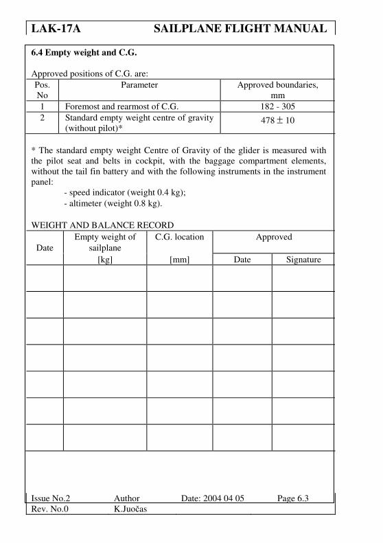
6.4 Empty weight and C.G.
Approved positions of C.G. are:
Pos. Parameter Approved boundaries,
No mm
1 Foremost and rearmost of C.G. 182 - 305
2 Standard empty weight centre of gravity
(without pilot)* 478 ± 10
* The standard empty weight Centre of Gravity of the glider is measured with
the pilot seat and belts in cockpit, with the baggage compartment elements,
without the tail fin battery and with the following instruments in the instrument
panel:
- speed indicator (weight 0.4 kg);
- altimeter (weight 0.8 kg).
WEIGHT AND BALANCE RECORD
Date
Empty weight of
sailplane
C.G. location Approved
[kg] [mm] Date Signature
Page 45
LAK-17A SAILPLANE FLIGHT MANUAL 0
Issue No.2 Author Date: 2004 04 05 Page 6.4
Rev. No.0 K.Juočas
Date
Empty sailplane
weight
C.G. location Approved
[kg] [mm] Date Signature
Page 46
LAK-17A SAILPLANE FLIGHT MANUAL 0
Issue No.2 Author Date: 2004 04 05 Page 6.5
Rev. No.0 K.Juočas
Note: The vertical tail fin battery (weight 3,5 kg) must be installed during
flight.
Taking the fin battery taking out moves the C.G. forward by:
~29 mm, when the glider is with water ballast, pilot 110kg;
~39 - 42 mm, when the glider is without water ballast, pilot 110kg.
Taking the battery in the luggage compartment out moves the C.G. of the
sailplane forward by approximately 2 - 3 mm.
Removable ballast used to supplement the weight of an occupant and parachute
(when lower than 70 kg) in order to keep the C.G. position within limits is
fastened in the fuselage nose. 1,75kg of removable ballast equals a pilot weight
of 5 kg.
The permissible range of centre of gravity for empty glider is given below.
LIMITS OF EMPTY MASS CENTER OF GRAVITY FOR LAK-17A
515,41
210
215
220
225
230
235
240
245
250
255
450 460 470 480 490 500 510 520 530 540 550 560 570 580
Empty Centre of Gravity position aft of DP, mm
Em
pty
mass, kg
Page 47
LAK-17A SAILPLANE FLIGHT MANUAL 0
Issue No.2 Author Date: 2004 04 05 Page 6.6
Rev. No.0 K.Juočas
6.5 Calculation of C.G. position
The centre of gravity position after loading the glider (additional instruments,
equipment, water ballast, pilot) is defined by:
∑
∑=
n
n
n
nn
CGG
XG
X
*
, mm;
Where: Gn = the glider`s component mass, kg;
Xn = distance between glider`s component mass C.G. and wing root
leading edge, mm;
distance “-“, if the mass C.G. is before the wing root leading edge;
distance “+” if the mass C.G. is behind the wing root leading edge;
n = number of the glider component mass;
ΣGn = sum of all glider component masses;
ΣGn * Xn = sum moments of all glider component masses;
Page 48
LAK-17A SAILPLANE FLIGHT MANUAL 0
Issue No.2 Author Date: 2004 04 05 Page 6.7
Rev. No.0 K.Juočas
The C.G. calculation table
No Component Weight
Gn;
kg
Distant
Xn;
mm
Moment
Gn* Xn;
kg * mm
1. Empty glider
2. Pilot
3. Battery in fin 3.5 4192
4. Battery in baggage
compartment
2.6 520
5. Water ballast in wings 168
6. Water ballast in fin 4003
7. Instrument N1 in
instrument
panel
-1010
8. Instrument N2 in
instrument
panel
9.
10
-
n-1 Removable ballast in
fuselage nose
(1-5) -1785
n Baggage weight 150
ΣΣΣΣGn= ΣΣΣΣGn * Xn=
∑
∑=
n
n
n
nn
CGG
XG
X
*
, mm
Page 49
LAK-17A SAILPLANE FLIGHT MANUAL 0
Issue No.2 Author Date: 2004 04 05 Page 6.8
Rev. No.0 K.Juočas
Note:
• The glider empty weight and empty weight centre of gravity are defined by
weighting data.
• Pilot: actual pilot weight with parachute:
distance X = -520, when pilot seat is in rearmost position;
distance X = -670, when pilot seat is in foremost position .
• Water ballast in the wings: actual filled water ballast weight.
• Water ballast in the fin: actual filled water ballast in fin tank weight.
• Baggage weight: weight of the baggage in a baggage compartment.
6.6 Weight of all non-lifting parts
The maximum approved weight of all non-lifting parts is 233 kg.
The actual weight of all non-lifting parts is equal to the empty weight, plus the
weight of the cockpit load (pilot, parachute, etc.), minus the weight of the
wings.
Weight of the wing: 58 - 61 kg for 15m and 60 - 63 kg for 18m.
6.7 Maximum weight
The maximum approved take-off and landing weight is 500 kg.
6.8 Useful loads
The maximum useful load of the LAK-17A is equal to the maximum approved
take-off and landing weight minus the empty weight of the aircraft and the
weight of any added water ballast.
Page 50
LAK-17A SAILPLANE FLIGHT MANUAL 0
Issue No.2 Author Date: 2004 04 05 Page 6.9
Rev. No.0 K.Juočas
6.9 Water ballast loading table
The example of how to define allowed amount of fin and wing water ballast is
given on a page 6.14 of this manual.
The max permissible wing water ballast weight (kg) is given in the
following table.
Maximum take-off mass 500 kg
Sailplane empty weight (kg) + fin ballast weight (kg)
Mass of pilot
with parachute
(kg) 220 225 230 235 240 245 250
70 180 180 180 180 180 180 180
75 180 180 180 180 180 180 175
80 180 180 180 180 180 175 170
85 180 180 180 180 175 170 165
90 180 180 180 175 170 165 160
95 180 180 175 170 165 160 155
100 180 175 170 165 160 155 150
105 175 170 165 160 155 150 145
110 170 165 160 155 150 145 140
Maximum capacity of wing tanks…....180 litre;
Maximum capacity of fin tank……...…..8 litre.
Page 51
LAK-17A SAILPLANE FLIGHT MANUAL 0
Issue No.2 Author Date: 2004 04 05 Page 6.10
Rev. No.0 K.Juočas
Allowed fin water ballast for pilot mass of 70 kg
Aft C.G. limits for fin tank water ballast
215
220
225
230
235
240
245
490 500 510 520 530 540 550 560 570 580
Empty C.G. position aft of DP, mm
Em
pty
ma
ss,
kg
Allowed fin water ballast for pilot mass of 75 kg
Aft C.G. limits for fin tank water ballast
215
220
225
230
235
240
245
490 500 510 520 530 540 550 560 570 580
Empty C.G. position aft of DP, mm
Em
pty
ma
ss, k
g
Page 52
LAK-17A SAILPLANE FLIGHT MANUAL 0
Issue No.2 Author Date: 2004 04 05 Page 6.11
Rev. No.0 K.Juočas
Allowed fin water ballast for pilot mass of 80 kg
Aft C.G. limits for fin tank water ballast
515,41
215
220
225
230
235
240
245
490 500 510 520 530 540 550 560 570 580
Empty C. G. position aft of DP, mm
Em
pty
mass
, k
g
Allowed fin water ballast for pilot mass of 85 kg
Aft C.G. limits for fin tank water ballast
215
220
225
230
235
240
245
490 500 510 520 530 540 550 560 570 580
Empty C.G. position aft of DP, mm
Em
pty
ma
ss,
kg
Page 53
LAK-17A SAILPLANE FLIGHT MANUAL 0
Issue No.2 Author Date: 2004 04 05 Page 6.12
Rev. No.0 K.Juočas
Allowed fin water ballast for pilot mass 90 kg
Aft limit for fin tank water ballast
215
220
225
230
235
240
245
490 500 510 520 530 540 550 560 570 580
Empty C.G. position aft of DP, mm
Em
pty
mass
, k
g
Allowed fin water ballast for pilot mass of 95 kg
Aft C.G. limits for fin tank water ballast
215
220
225
230
235
240
245
490 500 510 520 530 540 550 560 570 580
Empty C.G. position aft of DP, mm
Em
pty
ma
ss,
kg
Page 54
LAK-17A SAILPLANE FLIGHT MANUAL 0
Issue No.2 Author Date: 2004 04 05 Page 6.13
Rev. No.0 K.Juočas
Allowed fin water ballast for pilot mass of 100 kg
Aft limit for fin tank water ballast
215
220
225
230
235
240
245
490 500 510 520 530 540 550 560 570 580
Empty C.G. position aft of DP, mm
Em
pty
mass
, k
g
Allowed fin water ballast for pilot mass of 105 kg
AftC.G. limits for fin tank water ballast
215
220
225
230
235
240
245
500 510 520 530 540 550 560 570 580 590
Empty C.G. position aft of DP, mm
Em
pty
ma
ss,
kg
Page 55
LAK-17A SAILPLANE FLIGHT MANUAL 0
Issue No.2 Author Date: 2004 04 05 Page 6.14
Rev. No.0 K.Juočas
Allowed fin water ballast forpilot mass of 110 kg
Aft C.G. limits for fin tank water ballast
215
220
225
230
235
240
245
510 520 530 540 550 560 570 580 590 600 610 620
Empty C.G. position aft of DP, mm
Em
pty
mass
, k
g
Example of how to determine possible loading of the glider:
Sailplane empty weight………..…….. 236.9 kg;
Empty weight centre of gravity……… 515.4 mm;
Pilot with parachute weight……….… 80 kg;
Wing span…………………..……….. 18 m;
According to the graph “Limits of empty mass centre of gravity for LAK-
17A” (page 6.5) - the empty weight C.G. is in permissible range.
According to the graph “Allowed fin water ballast for pilot mass of 80 kg”
(page 6.11) – the allowed fin water ballast weight is 0 - 4 kg.
If:
• fin water ballast weight is 4 kg;
• sailplane empty weight + fin ballast weight = 236.9 kg + 4 kg =
240.9 kg ≈ 241 kg;
• pilot with parachute weight=80 kg;
according to the “Water ballast loading table” (page 6.9) - the max permissible
wing water ballast weight is ≈179 kg.
Page 56
LAK-17A SAILPLANE FLIGHT MANUAL 0
Issue No.2 Author Date: 2004 04 05 Page 7.1
Rev. No.0 K.Juočas
Section 7 SAILPLANE AND SYSTEMS DESCRIPTION
7.1 Introduction
7.2 Airframe construction
7.3 Flight controls and trim
7.4 Airbrakes and wheel brake
7.5 Flaps
7.6 Landing gear
7.7 Tow release
7.8 Canopy operation
7.9 Water ballast system
7.10 Cockpit ventilation
7.11 Seat back adjustment
7.12 Baggage compartment
7.13 Safety harness
7.14 Pitot and static pressure system
7.15 Miscellaneous equipment
7.15.1 Oxygen system
7.15.2 Emergency locator transmitter
7.16 Radio transceiver
Page 57
LAK-17A SAILPLANE FLIGHT MANUAL 0
Issue No.2 Author Date: 2004 04 05 Page 7.2
Rev. No.0 K.Juočas
7.1 Introduction
This Section provides a description of the sailplane, its systems and provided
standard equipment with instructions for use.
7.2 Airframe construction
The LAK-17A is a single seat high performance sailplane designed to meet FAI
15m and 18m Class requirements. The wings are constructed with glass and
carbon fibre reinforced plastic over a plastic foam core with carbon rod spar
caps. The ailerons are from carbon fibre reinforced plastic. The fuselage is made
using glass fibre reinforced plastic with Kevlar and carbon for local stiffness.
The stabilizer, elevator and rudder are glass fibre reinforced plastic over plastic
foam core.
7.3 Flight controls and trim
The ailerons and elevator are operated from the central control column (control
stick).
The trim adjustment control knob is located in
the left armrest and controls the elevator trim
select position. See Maintenance Manual Section
2. To set the trim simply move the adjustment
knob to the desired trim position.
Page 58
LAK-17A SAILPLANE FLIGHT MANUAL 0
Issue No.2 Author Date: 2004 04 05 Page 7.3
Rev. No.0 K.Juočas
The rudder pedals control the rudder by a cable system and
are adjusted using the grey knob located in the right arm rest.
Pull the knob to loosen the rudder pedal lock, make the
adjustment, and release the knob to lock the rudder pedals in
the desired position.
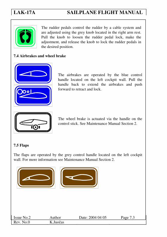
7.4 Airbrakes and wheel brake
The airbrakes are operated by the blue control
handle located on the left cockpit wall. Pull the
handle back to extend the airbrakes and push
forward to retract and lock.
The wheel brake is actuated via the handle on the
control stick. See Maintenance Manual Section 2.
7.5 Flaps
The flaps are operated by the grey control handle located on the left cockpit
wall. For more information see Maintenance Manual Section 2.
Page 59
LAK-17A SAILPLANE FLIGHT MANUAL 0
Issue No.2 Author Date: 2004 04 05 Page 7.4
Rev. No.0 K.Juočas
7.6 Landing gear
The landing gear is extended and retracted with the grey
control handle located in the right hand armrest.
Landing gear locked positions are located at either end
of the control handle travel. Forward to extend, back to
retract. The system is assisted by a nitrogen gas strut.
See Maintenance Manual Section2.
7.7 Tow release
The tow release is the yellow control knob located at
the left side wall of the cockpit. Pull this control knob
to open the tow release and release the knob to allow
the tow coupling to snap closed and lock.
7.8 Canopy operation
The canopy latching handles are red and white and
are located on either side of the canopy frame. Pull
the handles back to lock and push forward to un-lock.
Never use the window opening to lift or lower the
canopy. Cracks in the canopy will result.
When sitting in the cockpit use the small tabs on the
frame to raise and lower the canopy.
Page 60
LAK-17A SAILPLANE FLIGHT MANUAL 0
Issue No.2 Author Date: 2004 04 05 Page 7.5
Rev. No.0 K.Juočas
To jettison the canopy pull the red
canopy release handle firmly back
and release it. A spring will push
the front of the canopy up. This
allows the airflow to lift it up and
carry it away.
7.9 Water ballast system
In a standard configuration the tank valves for the wing and
tail open simultaneously with one knob.
The water ballast valves control knob is located on the right
side of the cockpit wall. To open the dump valves move the
knob to the back and to close the dump valves move the knob
forward.
(If the sailplane has an independent (optional) control system
for the fin tank valve - the water ballast valve control knob of
the fin tank is located on the right side of the cockpit wall. To
open the dump valve move the knob to the back and to close
the dump valve move the knob forward).
See Maintenance Manual Section 2.
7.10 Cockpit ventilation
The canopy de-mist vent control is located on the instrument
panel. Pull to open, push to close.
TAIL
TAIL
Page 61
LAK-17A SAILPLANE FLIGHT MANUAL 0
Issue No.2 Author Date: 2004 04 05 Page 7.6
Rev. No.0 K.Juočas
7.11 Seat back adjustment
Seat back adjustment is accomplished by using the squeeze ring located on the
left cockpit side.
7.12 Baggage compartment
Hard objects can not be carried in the baggage compartment without a suitably
designed lashing or anchorage. The baggage compartment load must not exceed
7 kg.
7.13 Safety harness
A safety harness with four fixed attachment points is provided.
7.14 Pitot and static pressure system
The fuselage-mounted tubes provide the pitot and static pressure.
Warning: An air leak will adversely affect airspeed indication and other
instruments. Make sure the probe is fully seated in the receptacle
for proper operation.
See Maintenance Manual Section 2.
Page 62
LAK-17A SAILPLANE FLIGHT MANUAL 0
Issue No.2 Author Date: 2004 04 05 Page 7.7
Rev. No.0 K.Juočas
7.15 Miscellaneous equipment
7.15.1 Oxygen system
The oxygen system (Aerox Oxygen, type E or M) must be operated in
accordance with the instructions provided by the manufacturer (Aerox Oxygen,
type E or M) of the system.
Caution: Installation of the oxygen system (Aerox Oxygen, type E or M)
must be accomplished by the aircraft manufacturer or by a
certified aircraft mechanic, according to national rules and
regulations. An authority aircraft inspector must approve the
installation.
7.15.2 Emergency locator transmitter
The system must be operated in accordance with the instructions provided by
the manufacturer of the Emergency Locator Transmitter system. See the
Maintenance Manual, Section 2, for recommended installation places.
Caution: Installation of the Emergency Locator Transmitter must be
accomplished by the aircraft manufacturer or by a certified
aircraft mechanic, according to National rules and regulations. An
authority aircraft inspector must approve the installation.
7.16 Radio transceiver
The radio station of type Becker or Filser should be used.
Page 63
LAK-17A SAILPLANE FLIGHT MANUAL 0
Issue No.2 Author Date: 2004 04 05 Page 8.1
Rev. No.0 K.Juočas
Section 8 SAILPLANE HANDLING, CARE AND MAINTENANCE
8.1 Introduction
8.2 Inspection periods and maintenance
8.3 Alterations and repairs
8.4 Tie down
8.5 Sailplane trailer
8.6 Ground handling
8.7 Cleaning
Page 64
LAK-17A SAILPLANE FLIGHT MANUAL 0
Issue No.2 Author Date: 2004 04 05 Page 8.2
Rev. No.0 K.Juočas
8.1 Introduction
This section contains the manufacturer's recommended procedures for proper
handling and servicing of the sailplane. It also identifies certain inspection and
maintenance activities, which are needed to retain performance and
dependability.
8.2 Inspection periods and maintenance
The Instructions for Continued Airworthiness as provided in the LAK-17A
Maintenance Manual must be followed. Before every rigging, all connecting
pins and bushings should be cleaned and greased. Also, at least once a year the
control surface displacements and adjustments must be inspected to insure
conformity with factory data. See the LAK-17A Maintenance Manual for
additional information.
8.3 Alterations and repairs
It is essential that the proper airworthiness authority be contacted prior to any
major alterations on this sailplane to insure that the airworthiness is not
impaired. Major alterations without approval from the manufacturer are
prohibited. Furthermore, the manufacturer will not be held liable for unproved
alterations or for damages resulting from changes in the characteristics of the
aircraft due to these alterations. External loads from camera installations are to
be regarded as major alterations. Repair instructions are located in the
Maintenance Manual Section 8. No repair should be performed to this aircraft
without referring to the Maintenance Manual. When in doubt as to the suitability
of a repair contact the manufacture.
Caution: No additional colour marking on the white upper surface is
allowed.
Page 65
LAK-17A SAILPLANE FLIGHT MANUAL 0
Issue No.2 Author Date: 2004 04 05 Page 8.3
Rev. No.0 K.Juočas
8.4 Tie down
The recommended tie down points are the tow release, wing tips and fuselage
tail just ahead of the vertical fin. The cockpit always must be closed and covered
when tied down.
Note: The external surfaces of the LAK-17A are finished in a durable epoxy
paint, however long exposure to sun and humidity will lead to
premature aging to any surface finish.
8.5 Sailplane trailer
A sailplane of this quality and value should be transported and stored in a high
quality enclosed trailer constructed of metal or fibreglass reinforced plastics.
Proper ventilation and UV blocking characteristics should be provided. The
wings should be supported as close as possible to the inner most root rib and
again at a point one-third from the wing tip. The horizontal stabilizer may be
stored vertically or horizontally. The fuselage should be supported in a fuselage
dolly positioned just forward of the main landing wheel opening. Due to the
angle of the fuselage in the trailer a forward stop must be provided for the
fuselage dolly. Otherwise it will roll forward and leave the fuselage with no
support. Forward and aft motion of the fuselage should be restricted with a felt
lined nose cone support and a tail wheel well with a fuselage strap located just
forward of the vertical fin.
Page 66
LAK-17A SAILPLANE FLIGHT MANUAL 0
Issue No.2 Author Date: 2004 04 05 Page 8.4
Rev. No.0 K.Juočas
8.6 Ground handling
Ground towing should be accomplished using the tow release and standard
double aerotow ring. Ground towing should also be accomplished with a tail
dolly tow bar and wing tip wheel.
8.7 Cleaning
The exterior painted surfaces should be cleaned with clear water using a sponge
or soft cotton towel and chamois. These surfaces should also be protected with a
silicone free hard wax reapplied at least once a year by hand or with a rotating
cloth disc. Tape adhesives are best removed using pure petroleum spirits or wax
containing a light polishing agent. Do not clean the exterior surfaces with
alcohol, acetone or lacquer thinner.
Clean the Plexiglas canopy only as necessary using a soft cotton towel and clear
water mixed with a small amount of mild detergent. Protect the canopy with
anti-static cleaning agents which are made specifically for Plexiglas.
All non-painted metal surfaces must be regularly wiped clean and protected with
a light coating of grease.
Page 67
LAK-17A SAILPLANE FLIGHT MANUAL 0
Issue No.2 Author Date: 2004 04 05 Page 9.1
Rev. No.0 K.Juočas
Section 9
SUPPLEMENTS
There are no supplements