8:00am - 9:00pm EST M-Th8:00am - 7:00pm EST Friday9:00am - 2:00pm EST Saturday
Liability StatementSuperATV’s® products are designed to best fit user’s ATV/UTV under stock conditions. Adding, modifying, or fabricating any factory or aftermarket parts will void any warranty provided by SuperATV® and is not recommended. SuperATV’s®
products could interfere with other aftermarket accessories. If user has aftermarket products on machine, contact SuperATV® to verify that they will work together.Although SuperATV® has thousands of satisfied customers, user should be aware that installing lift kits, long travel, or suspension kits, tires, etc. will change the ride of machine and may increase maintenance and part wear. Operating any off-road machine while, or after, consuming alcohol and/or drugs increases risk of bodily harm or death. No warranty or representation is made as to this product’s ability to protect user from severe injury or death. SuperATV® urges operators and occupants to wear a helmet and appropriate riding gear at all times.By purchasing and installing SuperATV® products, user agrees that should damages occur, SuperATV® will not be held responsible for loss of time, use, labor fees, replacement parts, or freight charges. SuperATV®, nor any 3rd party, will not be held responsible for any direct, indirect, incidental, special, or consequential damages that result from any product purchased from SuperATV®. The total liability of seller to user for all damages, losses, and causes of action, if any, shall not exceed the total purchase price paid for the product that gave rise to the claim.SuperATV® will warranty only parts provided by SuperATV®. Any damage or problems with OEM housings, bearings, seals, or other manufacturers’ products will not be covered by SuperATV®. SuperATV® parts and products are not warrantied if item was not installed properly, misused, or modified.
Windshield Cleaning:- Do not use window cleaning fluids (Windex, 409, etc) or any solvents (gasoline, denatured alcohol, acetone, etc).- Never use abrasive cleaners, abrasive pads, or gritty cloths.- Never use razor blades, scrapers, sqeegees, brushes, etc.1. Thouroughly rinse Windshield to float off dirt and mud.2. Using a soft cloth, or microfiber cloth, clean Windshield with warm water and a gentle detergent. Baby shampoo
or hand washing soap are recommended.3. To prevent water spots, use a chamois to blot Windshield dry.
Rubber must face Windshield when installing Sealing Washer
M6-1.0 x 30mm Lg. BHCS4x
M8-1.25 x 55mm Lg. FHCS1x
IN-FWS-P-GEN1K4
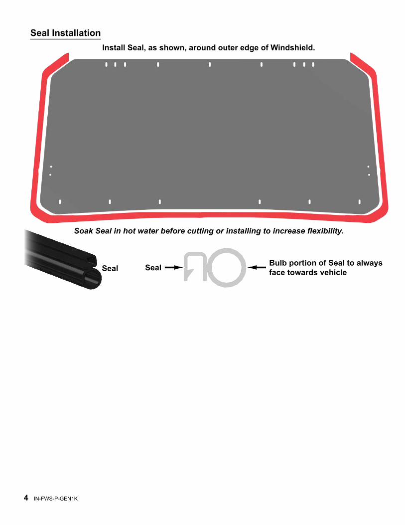
Seal Installation
Soak Seal in hot water before cutting or installing to increase flexibility.
Bulb portion of Seal to always face towards vehicleSealSeal
Install Seal, as shown, around outer edge of Windshield.
IN-FWS-P-GEN1K5
(driver side)
remove Roof
(passenger side)
remove Sound Bar
remove Visor Panel
IN-FWS-P-GEN1K6
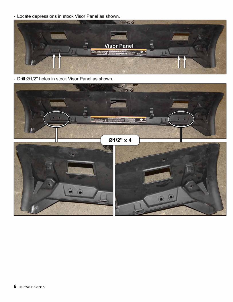
- Drill Ø1/2" holes in stock Visor Panel as shown.
Ø1/2" x 4
Visor Panel
- Locate depressions in stock Visor Panel as shown.
IN-FWS-P-GEN1K7
J
- In
stal
l Piv
ot B
lock
s (J
) and
Low
er F
ram
e (N
) to
Win
dshi
eld
(A) w
ith h
ardw
are
show
n.
N
M6 x 20mmSe
alin
g W
ashe
r
6 ea
ch
A
M6
Nyl
ock
Nut
IN-F
WS
-P-G
EN
1K7
M6
x 20
mm
M6
Jam
Nut
Seal
ing
Was
her
(2) e
ach
per
Pivo
t Blo
ck (J
)
IN-FWS-P-GEN1K8
IN-F
WS
-P-G
EN
1K8
- In
stal
l Top
Fra
me
(D) t
o W
inds
hiel
d (A
) with
ha
rdw
are
show
n.-
Inst
all R
ight
/Lef
t Fem
ale
Hin
ges
(F-G
) to
Win
dshi
eld
(A) a
nd T
op F
ram
e (D
) with
ha
rdw
are
show
n.
D
FA
G
M6 x 20mm
Seal
ing
Was
her
5 ea
ch
M6
Nyl
ock
Nut
(2) e
ach
per
Fem
ale
Hin
ge
Seal
ing
Was
her
M6
Nyl
ock
Nut
(pas
seng
er s
ide)
(bot
tom
)
M6
x 30
mm
IN-FWS-P-GEN1K9
(driver side)
- Place Windshield onto machine.- Install Male Hinges (E-H) into Female Hinges (F-G).
Provided Spacer must be installed.- Secure Male Hinges (E-H) to Frame with hardware shown.
E
HA
(driver side inside machine)
(2) each per Male Hinge
M10 Nut
H
G
From this step forward, installation is easiest with an extra set of hands.
Install provided Spacer
M10
x 3
0mm
IN-FWS-P-GEN1K10
Hinge AlignmentTo avoid binding when opening and closing Windshield, align Hinges before tightening hardware.
in-line
Seal to be in contact with Cage Frame and Dash
- Align to machine and tighten all hardware completely.
IN-FWS-P-GEN1K11
(driver side)
C
L
M
- Place Inner Strut Clamp (L) and Outer Strut Clamp (M) around Cab Frame as shown.- Install Gas Strut (C) to Inner Inner Strut Clamp (L).- Secure with hardware shown.- Repeat for opposite side.
ML
M6 Nut
2 each
Cab Frame
M6 x 20mm
IN-FWS-P-GEN1K12
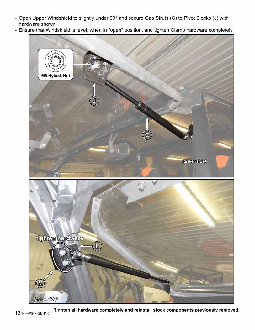
- Open Upper Windshield to slightly under 90° and secure Gas Struts (C) to Pivot Blocks (J) with hardware shown.
- Ensure that Windshield is level, when in "open" position, and tighten Clamp hardware completely.
M
L
(driver side)
tighten hardware
Tighten all hardware completely and reinstall stock components previously removed.
(driver side)
C
J
M8 Nylock Nut
IN-FWS-P-GEN1K13
Catch (K) installation
(passenger side)
- Install Latches (K) onto Handle.
K
Handle
(driver side)
- Use a strap to keep Windshield in closed postition.
IN-FWS-P-GEN1K14
Catch (K) installation continued- Place tape on Dash and mark Latch (K) locations.
Tape
K
- Drill (4) Ø7mm holes through Dash.
IN-FWS-P-GEN1K15
- Remove Center Storage.
Center Storage
Catch (K) installation continued
- Install Handle Support (P) to Frame with hardware shown.- Install Catches (K) to Dash and Handle Support with hardware shown.- Tighten hardware completely and replace Center Storage.