APPROVED FOR PUBLIC RELEASE; DISTRIBUTION UNLIMITED. STINFO COPY AIR FORCE RESEARCH LABORATORY INFORMATION DIRECTORATE SINGLE PHOTON HOLOGRAPHIC QUDIT ELEMENTS FOR LINEAR OPTICAL QUANTUM COMPUTING FLORIDA ATLANTIC UNIVERSITY MAY 2011 FINAL TECHNICAL REPORT ROME, NY 13441 UNITED STATES AIR FORCE AIR FORCE MATERIEL COMMAND AFRL-RI-RS-TR-2011-095
Transcript
APPROVED FOR PUBLIC RELEASE; DISTRIBUTION UNLIMITED.
STINFO COPY
AIR FORCE RESEARCH LABORATORY INFORMATION DIRECTORATE
SINGLE PHOTON HOLOGRAPHIC QUDIT ELEMENTS FOR LINEAR
OPTICAL QUANTUM COMPUTING
FLORIDA ATLANTIC UNIVERSITY
MAY 2011
FINAL TECHNICAL REPORT
ROME, NY 13441 UNITED STATES AIR FORCE AIR FORCE MATERIEL COMMAND
AFRL-RI-RS-TR-2011-095
NOTICE AND SIGNATURE PAGE
Using Government drawings, specifications, or other data included in this document for
any purpose other than Government procurement does not in any way obligate the U.S.
Government. The fact that the Government formulated or supplied the drawings,
specifications, or other data does not license the holder or any other person or
corporation; or convey any rights or permission to manufacture, use, or sell any patented
invention that may relate to them.
This report was cleared for public release by the 88th
ABW, Wright-Patterson AFB
Public Affairs Office and is available to the general public, including foreign nationals.
Copies may be obtained from the Defense Technical Information Center (DTIC)
(http://www.dtic.mil).
AFRL-RI-RS-TR-2011-095 HAS BEEN REVIEWED AND IS APPROVED FOR
PUBLICATION IN ACCORDANCE WITH ASSIGNED DISTRIBUTION
STATEMENT.
FOR THE DIRECTOR:
/s/ /s/
PAUL M. ALSING MICHAEL J. HAYDUK, Acting Chief
Work Unit Manager Advanced Computing Division
Information Directorate
This report is published in the interest of scientific and technical information exchange, and its
publication does not constitute the Government’s approval or disapproval of its ideas or findings.
REPORT DOCUMENTATION PAGE Form Approved
OMB No. 0704-0188
Public reporting burden for this collection of information is estimated to average 1 hour per response, including the time for reviewing instructions, searching data sources, gathering and maintaining the data needed, and completing and reviewing the collection of information. Send comments regarding this burden estimate or any other aspect of this collection of information, including suggestions for reducing this burden to Washington Headquarters Service, Directorate for Information Operations and Reports, 1215 Jefferson Davis Highway, Suite 1204, Arlington, VA 22202-4302, and to the Office of Management and Budget, Paperwork Reduction Project (0704-0188) Washington, DC 20503. PLEASE DO NOT RETURN YOUR FORM TO THE ABOVE ADDRESS. 1. REPORT DATE (DD-MM-YYYY)
May 2011 2. REPORT TYPE
Final Technical Report 3. DATES COVERED (From - To)
October 2009 – October 2010
4. TITLE AND SUBTITLE
SINGLE PHOTON HOLOGRAPHIC QUDIT ELEMENTS FOR LINEAR
OPTICAL QUANTUM COMPUTING
5a. CONTRACT NUMBER N/A
5b. GRANT NUMBER FA8750-10-2-0017
5c. PROGRAM ELEMENT NUMBER 62788F
6. AUTHOR(S)
Warner Miller
5d. PROJECT NUMBER T2AQ
5e. TASK NUMBER SP
5f. WORK UNIT NUMBER HQ
7. PERFORMING ORGANIZATION NAME(S) AND ADDRESS(ES) Florida Atlantic University
777 Glades Road
Boca Raton, FL 33486
8. PERFORMING ORGANIZATION REPORT NUMBER
N/A
9. SPONSORING/MONITORING AGENCY NAME(S) AND ADDRESS(ES)
Air Force Research Laboratory/RITC
525 Brooks Road
Rome NY 13441-4505
10. SPONSOR/MONITOR'S ACRONYM(S) AFRL/RI
11. SPONSORING/MONITORING AGENCY REPORT NUMBER AFRL-RI-RS-TR-2011-095
12. DISTRIBUTION AVAILABILITY STATEMENT Approved for Public Release; Distribution Unlimited. PA# 88ABW-2011-2464 Date Cleared: 3 May 2011
13. SUPPLEMENTARY NOTES
14. ABSTRACT The operational objective of this project is to demonstrate that a small, lightweight, field-deployable, low-cost quantum algorithm
(e.g. Grover’s search algorithm) is feasible using existing technology. We have designed such optical elements and have begun a
collaboration with CREOL (Leonid Glebov) to manufacture such gates for experimental demonstration of the results under this
effort. Our technical objective of this project was the simulation and design of fundamental quantum logic gates, each encoded as a
multiplexed volume hologram (VH) within a single piece of Photo-Thermal Refractive (PTR) glass. The approach we used to
accomplished this is (1) the simulation of volume hologram on AFRL GP/GPU machines using a split-operator method , (2)
mathematical modeling based on extensions of the coupled-mode theory, as well as (3) V&V.
15. SUBJECT TERMS
Orbital angular momentum photons, qudits, volume hologram, holographic sorter, QKD
16. SECURITY CLASSIFICATION OF: 17. LIMITATION OF ABSTRACT
UU
18. NUMBER OF PAGES
17
19a. NAME OF RESPONSIBLE PERSON
PAUL M. ALSING a. REPORT
U b. ABSTRACT
U c. THIS PAGE
U 19b. TELEPHONE NUMBER (Include area code)
N/A Standard Form 298 (Rev. 8-98)
Prescribed by ANSI Std. Z39.18
CONTENTS 1 SUMMARY 1 2 INTRODUCTION 1 3 METHODS, ASSUMPTIONS AND PROCEDURES 2 3.1 Four Metrics and Milestones and Accomplishments 2 3.2 Publications Under this Effort 3 4 RESULTS AND DISCUSSION 3 4.1 Design of Optical Quantum Computing CNOT Gate 3 4.2 The efficiency of an OAM and LM Volume Grating 5 4.3 Coupled-Mode Analysis of a Single OAM Grating 7 4.4 Coupled-Mode Analysis of the LM Sorter 10 5 CONCLUSIONS 10 6 LIST OF SYMBOLS, ABBREVIATIONS AND ACRONYMS 11 7 REFERENCES 12
APPROVED FOR PUBLIC RELEASE; DISTRIBUTION UNLIMITED.
i
List of Figures 1 Volume holographic design of the 4-dimensional CNOT gate in PTR glass. The gate can be constructed by a stack of 4 LM gratings, or by a stack of two multiplexed gratings 4 2 OAM volume hologram sorter 6 3 Contour plot of the index of refraction 6 4 Intensity for (left) Gaussian-beam, (right) L = 1 LG beam 7 5 Predicted bit error rate (BER) 7 6 Farfield diffraction pattern of the solution of Eqns. 20 & 21 9 7 A 3D FTDT simulation of the OAM grating 10
APPROVED FOR PUBLIC RELEASE; DISTRIBUTION UNLIMITED.
ii
1 SUMMARYThe operational objective of this project is to demonstrate that a small, lightweight, field-deployable,low-cost quantum algorithm (e.g. Grover’s search algorithm) is feasible using existing technology.We have designed such optical elements and have begun a collaboration with Leonid Glebov of theThe College of Optics & Photonics (CREOL) to manufacture such gates for experimental demon-stration of the results under this effort. Our technical objective of this project was the simulationand design of fundamental quantum logic gates, each encoded as a multiplexed volume hologram(VH) within a single piece of Photo-Thermal Refractive (PTR) glass. The approach we used toaccomplish this is (1) the simulation of a volume hologram on Air Force Research Laboratory(AFRL) General Purpose Graphical Processing Unit (GP/GPU) machines using a split-operatormethod, (2) mathematical modeling based on extensions of the coupled-mode theory, as well as(3) verification and visualization (V&V).
2 INTRODUCTIONVarious approaches have been proposed for quantum computation. The most familiar of these isthe quantum circuit model (QCM) [1]. Here the challenge is to (1) simulate those families of uni-tary operations on n quantum bits (qubits) that scale polynomially in n by small quantum circuits,and (2) project the readout onto the computational basis and measure the “output state.” One appli-cation of this quantum circuit model involves linear optical quantum computing (LOQC) [2] andone-way quantum computing (OWQC) [3]. These are also known as cluster state quantum com-puting (CSQC) [4]. The essential feature of these approaches involve either a non-linear measuringprocess and/or the preparation of a highly-entangled n-qubit initial computational state. Here a se-quence of measurements are made, projected onto one or another of the mutually-unbiased bases(MUBs). In our research we examined the utility of higher dimensional state spaces, i.e quantum d-level states (qudits), for LOQC. In addition to examining the potential strengths and weaknesses ofqudit LOQC we extend our previous developments [5] in optical volume holography and designedand simulated practical single-photon, single-optical elements for qudit MUB-state quantum in-formation processing. This includes the design of accurate MUB sorters and other relevant quditunitary operators for LOQC. Our designs are based on coupled-mode analysis and its extensions;however, this approximation was further verified by numerical modeling. We developed a split-operator method running on AFRL GP/GPU computers.
An increase in the dimension of state space for quantum information processing (QIP) canincrease tolerance to bit error rate (BER) while also increasing its bandwidth. The potential ofextending photon-based QIP to higher dimensions was made popular in 1992 when Allen et al.[8] showed that Laguerre-Gaussian light beams possessed a quantized orbital angular momentum(OAM) of ℏ per photon. In 1983 Miller and Wheeler were the first to introduce fundamentalquantum experiments using photons in OAM quantum states [9]. This opened up an arbitrarilyhigh dimensional quantum space to a single photon [10]. Following these discoveries Mair et al.[11,12] unequivocally demonstrated the quantum nature of photon OAM by showing that pairs ofOAM photons can be entangled using parametric down conversion. Shortly thereafter, Molina-Terriza et al. [13] introduced a scheme to prepare photons in multidimensional vector states ofOAM commencing OAM QIP.
While photons with specific values of OAM have been emphasized in the literature we canequally well utilize any other set of orthogonal basis functions for higher-dimensional quantum
1
APPROVED FOR PUBLIC RELEASE; DISTRIBUTION UNLIMITED.
key distribution (QKD). While OAM states respect azimuthal symmetry, linear momentum (LM)states respect rectilinear symmetry. Independent of the representation we use, the MUB stateswill ordinarily be modulated in both amplitude and phase. Recently a practical method has beendemonstrated to produce such MUB states using computer-generated holography with a singlespatial light modulator (SLM) [6].
A significant obstacle for quantum computing with qudits (d ≥ 3) has been an efficient andpractical quantum state sorter for photons whose complex fields are modulated in both amplitudeand phase. We propose here such a sorter based on a multiplexed thick hologram, constructed e.g.from PTR glass, and demonstrate how such elements can be used to construct a practical quantumgate. We will validate this approach using coupled-mode theory with parameters consistent withPTR glass and simulate and validate the holographic sorter numerically. Our models will assumeboth two and three-dimensional state space spanned by three tilted plane waves. We extend ouranalysis to three dimensions, as this is one more dimension than available with photon polarizationstates. We will explore the utility of such a sorter for broader QIP and we believe that its impactcan be substantial to quantum computing.
3 METHODS, ASSUMPTIONS AND PROCEDURES
3.1 Four Metrics and Milestones and Accomplishments.
We addressed four primary metrics throughout this research effort. First, (Metric 1) we devel-oped a split-operator code to provide an explicit simulation (split-operator method) and analyticmodel (coupled-mode theory) of a fundamental quantum logic gate recorded in a single pieceof PTR glass. In particular, we designed and solved via coupled-mode theory the function of avolume-holographic Pauli-z gate as well as the quantum NOT gate and a quantum-state sorter.These coupled-mode results were further verified with a split operator method as well as a finite-difference time-domain (FDTD) code from Massachusetts Institute of Technology’s (MIT’s) MITelectromagnetic equation propagation code (Meep). Secondly, (Metric 2) all simulations weresuitably benchmarked against analytic and known solutions and our simulations were run onAFRL high performance computing (HPC) GP/GPU and message passing interface (MPI) plat-forms. Our undergraduate student (UG) student (Chris Tison) worked under the summer internprogram at AFRL’s Emerging Computing Technology Group (RITC) and migrated our codes tothe AFRL/RITC Nvidia GPU cluster. We collaborated with Leonid Glebov’s group at the Univer-sity of Central Florida. Together we ascertained that multiplexing with high fidelity was indeedpossible in photo-thermal refractive (PTR) glass. Furthermore, the CREOL research group de-termined that it takes roughly one millimeter of PTR glass per exposure in order to achieve highfidelity multiplexed gratings. Furthermore, PTR holograms can approach thicknesses of 2 cm.Therefore, we can, in principle, compute in a 20-dimensional quantum state space. This limitsthis technology to a linear optical quantum computer such that each quantum gate has to use lessthan five or fewer qubits. It is well known that this technology is not scalable; however, there maybe many quantum information processing tasks that may require a relatively small (≤ 5) amountof bits (i.e. quantum error correction). These findings, together with our designs, models, andsimulations, demonstrate that a small, lightweight, field-deployable, low-cost quantum algorithm(e.g. Grover’s search algorithm) is feasible using existing technology. Finally (Metric 4), we havea paper accepted for the March 2011 International Society for Optics and Photonics (SPIE) De-fense, Security and Sensing meeting in Quantum Information and Computation IX. (Paper number
2
APPROVED FOR PUBLIC RELEASE; DISTRIBUTION UNLIMITED.
8057-27, 29 Aug 2011.). In this paper the simulation of a fundamental quantum logic gate will besubmitted for public release and publication in a refereed journal.
We met or exceeded all four metrics and milestones described above. In particular, we designedand simulated a high-fidelity volume hologram (VH) qubit logic gate. Our simulations were doneboth at Florida Atlantic University (FAU), and at AFRL during the summer by an FAU UG student(Chris Tison). We leveraged this AFRL grant and received approval from FAU to purchase a7 teraflop GPU computer for student training purposes. This Nvidia computer is similar to theNvidia machines used at AFRL. This enabled our student to immediately show progress under thesummer internship at AFRL. In order to continue this research the FAU Principal Investigator (PI)and United States (US) student were given H-token access to AFRL compute facilities. Both thePI and student (C. Tison) spent the summer at AFRL’s Information Directorate (RI). During thisgrant period we successfully provided a GPU simulation of a VH quantum gate using our paraxialsplit operator code. As a follow-on to this grant, we presented a specific design for the fabricationof a PTR qubit VH at a December 2010 kickoff meeting at CREOL with Leonid Glebov’s group.
During this effort we analyzed two independent sets of quantum states of a photon that wouldallow us to explore higher-dimensional state spaces. One quantized the transverse LM (tilt of thewavefront) of the photon while the other quantized the photon’s OAM. We extensively analyzed theefficiency of OAM verses LM volume holographic gratings and concluded that higher efficienciescould be reasonably achieved with LM states thus arguing against the use of photons with OAM.
3.2 Publications Under this Effort
There are three publications in refereed journals associated to this effort, one poster contribution,and three seminars. The publications are as follows:
1. W. Miller, “Efficient Photon Sorter in a High Dimensional State Space,” Journal QuantumInformation and Computation, Vol. 11, No. 3&4 (2011) 0313.
2. SPIE Defense, Security and Sensing paper accepted. P. Alsing, G. Kreymerman, J. Mc-Donald, W. Miller, and C. Tison, “Quantum Computing in a Piece of Glass,” in QuantumInformation and Computation IX. Paper number 8057-27, 29 Aug 2011.
3. P. Alsing, G. Kreymerman, W. Miller and C. Tison, Volume Holographic Gratings for Pho-tons with Orbital Angular Momentum, in preparation.
4 RESULTS AND DISCUSSION
4.1 Design of Optical Quantum Computing CNOT Gate
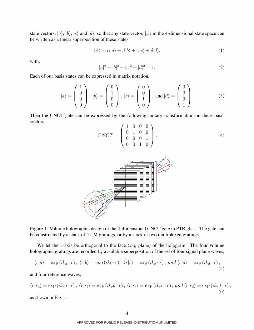
Here we provide a specific design of a quantum controlled not (CNOT) gate in PTR glass. Wecould have chosen any 2 or 4-qubit gates, but chose this one to illustrate our design as it is acanonical example found in the literature. The CNOT gate is a 2-qubit gate. This is a 2 × 2, or4-dimensional state space. This state space can be constructed as a product space of qubits, e.g.by utilizing the polarization states of two correlated photons. However, in a higher-dimensionalstate space such as that afforded by the LM photon states the CNOT gate can be constructed witha single photon. In our design, we choose four independent plane waves lying on the cone shownin Figure 1. We associate these independent transverse LM modes with the orthogonal quantum
3
APPROVED FOR PUBLIC RELEASE; DISTRIBUTION UNLIMITED.
state vectors, ∣a⟩, ∣b⟩, ∣c⟩ and ∣d⟩, so that any state vector, ∣ ⟩ in the 4-dimensional state space canbe written as a linear superposition of these states,
∣ ⟩ = �∣a⟩+ �∣b⟩+ ∣c⟩+ �∣d⟩, (1)
with,∣a∣2 + ∣b∣2 + ∣c∣2 + ∣d∣2 = 1. (2)
Each of our basis states can be expressed in matrix notation,
∣a⟩ =
⎛⎜⎜⎝
1000
⎞⎟⎟⎠ , ∣b⟩ =
⎛⎜⎜⎝
0100
⎞⎟⎟⎠ , ∣c⟩ =
⎛⎜⎜⎝
0010
⎞⎟⎟⎠ , and ∣d⟩ =
⎛⎜⎜⎝
0001
⎞⎟⎟⎠ . (3)
Then the CNOT gate can be expressed by the following unitary transformation on these basisvectors:
CNOT =
⎛⎜⎜⎝
1 0 0 00 1 0 00 0 0 10 0 1 0
⎞⎟⎟⎠ . (4)
b
b
ab
c
d
rc
rd
c rc
d rd
d rc
c rd
ab
c
d
z
x
y
rarb
Figure 1: Volume holographic design of the 4-dimensional CNOT gate in PTR glass. The gate canbe constructed by a stack of 4 LM gratings, or by a stack of two multiplexed gratings.
We let the z-axis be orthogonal to the face (x-y plane) of the hologram. The four volumeholographic gratings are recorded by a suitable superposition of the set of four signal plane waves,
APPROVED FOR PUBLIC RELEASE; DISTRIBUTION UNLIMITED.
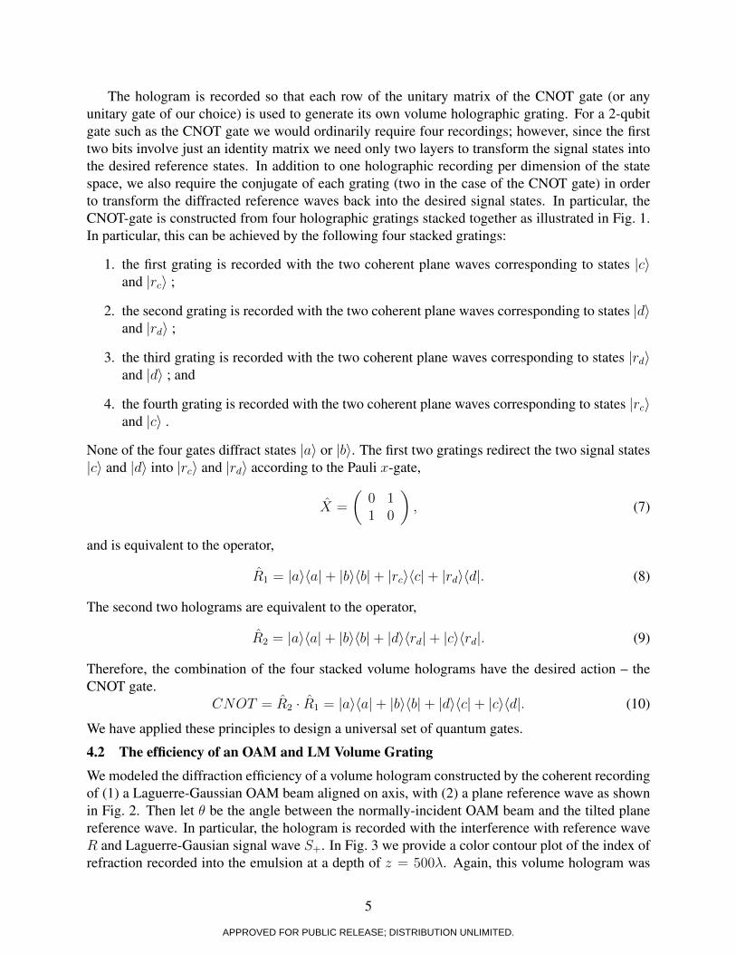
The hologram is recorded so that each row of the unitary matrix of the CNOT gate (or anyunitary gate of our choice) is used to generate its own volume holographic grating. For a 2-qubitgate such as the CNOT gate we would ordinarily require four recordings; however, since the firsttwo bits involve just an identity matrix we need only two layers to transform the signal states intothe desired reference states. In addition to one holographic recording per dimension of the statespace, we also require the conjugate of each grating (two in the case of the CNOT gate) in orderto transform the diffracted reference waves back into the desired signal states. In particular, theCNOT-gate is constructed from four holographic gratings stacked together as illustrated in Fig. 1.In particular, this can be achieved by the following four stacked gratings:
1. the first grating is recorded with the two coherent plane waves corresponding to states ∣c⟩and ∣rc⟩ ;
2. the second grating is recorded with the two coherent plane waves corresponding to states ∣d⟩and ∣rd⟩ ;
3. the third grating is recorded with the two coherent plane waves corresponding to states ∣rd⟩and ∣d⟩ ; and
4. the fourth grating is recorded with the two coherent plane waves corresponding to states ∣rc⟩and ∣c⟩ .
None of the four gates diffract states ∣a⟩ or ∣b⟩. The first two gratings redirect the two signal states∣c⟩ and ∣d⟩ into ∣rc⟩ and ∣rd⟩ according to the Pauli x-gate,
X =
(0 11 0
), (7)
and is equivalent to the operator,
R1 = ∣a⟩⟨a∣+ ∣b⟩⟨b∣+ ∣rc⟩⟨c∣+ ∣rd⟩⟨d∣. (8)
The second two holograms are equivalent to the operator,
R2 = ∣a⟩⟨a∣+ ∣b⟩⟨b∣+ ∣d⟩⟨rd∣+ ∣c⟩⟨rd∣. (9)
Therefore, the combination of the four stacked volume holograms have the desired action – theCNOT gate.
We have applied these principles to design a universal set of quantum gates.
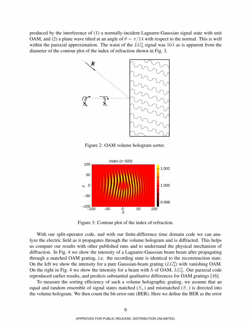
4.2 The efficiency of an OAM and LM Volume Grating
We modeled the diffraction efficiency of a volume hologram constructed by the coherent recordingof (1) a Laguerre-Gaussian OAM beam aligned on axis, with (2) a plane reference wave as shownin Fig. 2. Then let � be the angle between the normally-incident OAM beam and the tilted planereference wave. In particular, the hologram is recorded with the interference with reference waveR and Laguerre-Gausian signal wave S+. In Fig. 3 we provide a color contour plot of the index ofrefraction recorded into the emulsion at a depth of z = 500�. Again, this volume hologram was
5
APPROVED FOR PUBLIC RELEASE; DISTRIBUTION UNLIMITED.
produced by the interference of (1) a normally-incident Laguarre-Gaussian signal state with unitOAM, and (2) a plane wave tilted at an angle of � = �/14 with respect to the normal. This is wellwithin the paraxial approximation. The waist of the LG1
0 signal was 50� as is apparent from thediameter of the contour plot of the index of refraction shown in Fig. 3.
S+ S_
R
Figure 2: OAM volume hologram sorter.
–100 –50 0 50 100–100
–50
0
50
100
X
y
Index (z~500)
0.998
1.000
1.002
Figure 3: Contour plot of the index of refraction.
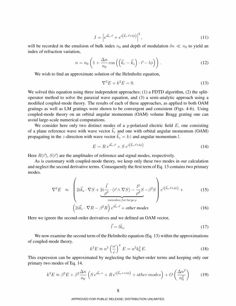
With our split-operator code, and with our finite-difference time domain code we can ana-lyze the electric field as it propagates through the volume hologram and is diffracted. This helpsus compare our results with other published runs and to understand the physical mechanism ofdiffraction. In Fig. 4 we show the intensity of a Laguarre-Gaussian beam beam after propagatingthrough a matched OAM grating, i.e. the recording state is identical to the reconstruction state.On the left we show the intensity for a pure Gaussian-beam grating (LG0
0) with vanishing OAM.On the right in Fig. 4 we show the intensity for a beam with ℏ of OAM, LG1
0. Our paraxial codereproduced earlier results, and predicts substantial qualitative differences for OAM gratings [16].
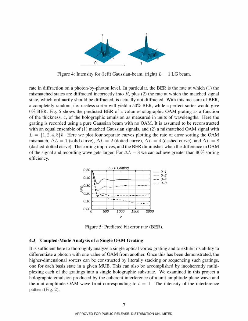
To measure the sorting efficiency of such a volume holographic grating, we assume that anequal and random ensemble of signal states matched (S+) and mismatched (S−) is directed intothe volume hologram. We then count the bit error rate (BER). Here we define the BER as the error
6
APPROVED FOR PUBLIC RELEASE; DISTRIBUTION UNLIMITED.
Figure 4: Intensity for (left) Gaussian-beam, (right) L = 1 LG beam.
rate in diffraction on a photon-by-photon level. In particular, the BER is the rate at which (1) themismatched states are diffracted incorrectly into R, plus (2) the rate at which the matched signalstate, which ordinarily should be diffracted, is actually not diffracted. With this measure of BER,a completely random, i.e. useless sorter will yield a 50% BER, while a perfect sorter would give0% BER. Fig. 5 shows the predicted BER of a volume-holographic OAM grating as a functionof the thickness, z, of the holographic emulsion as measured in units of wavelengths. Here thegrating is recorded using a pure Gaussian beam with no OAM. It is assumed to be reconstructedwith an equal ensemble of (1) matched Gaussian signals, and (2) a mismatched OAM signal withL = {1, 2, 4, 8}ℏ. Here we plot four separate curves plotting the rate of error sorting the OAMmismatch, ΔL = 1 (solid curve), ΔL = 2 (dotted curve), ΔL = 4 (dashed curve), and ΔL = 8(dashed-dotted curve). The sorting improves, and the BER diminishes when the difference in OAMof the signal and recording wave gets larger. For ΔL = 8 we can achieve greater than 90% sortingefficiency.
0 500 1000 1500 20000.00
0.10
0.20
0.30
0.40
0.50
z
BER
LG 0 Grating0–10–20–40–8
Figure 5: Predicted bit error rate (BER).
4.3 Coupled-Mode Analysis of a Single OAM Grating
It is sufficient here to thoroughly analyze a single optical vortex grating and to exhibit its ability todifferentiate a photon with one value of OAM from another. Once this has been demonstrated, thehigher-dimensional sorters can be constructed by literally stacking or sequencing such gratings,one for each basis state in a given MUB. This can also be accomplished by incoherently multi-plexing each of the gratings into a single holographic substrate. We examined in this project aholographic emulsion produced by the coherent interference of a unit-amplitude plane wave andthe unit amplitude OAM wave front corresponding to l = 1. The intensity of the interferencepattern (Fig. 2),
7
APPROVED FOR PUBLIC RELEASE; DISTRIBUTION UNLIMITED.
I =∣∣∣eikr⋅r + ei(ks⋅r+l�)
∣∣∣2
, (11)
will be recorded in the emulsion of bulk index n0 and depth of modulation �n ≪ n0 to yield anindex of refraction variation,
n = n0
(1 +
Δn
n0
cos((kr − ks
)⋅ r − l�
)). (12)
We wish to find an approximate solution of the Helmholtz equation,
∇2E + k2E = 0. (13)
We solved this equation using three independent approaches; (1) a FDTD algorithm, (2) the split-operator method to solve the paraxial wave equation, and (3) a semi-analytic approach using amodified coupled-mode theory. The results of each of these approaches, as applied to both OAMgratings as well as LM gratings were shown to be convergent and consistent (Figs. 4-6). Usingcoupled-mode theory on an orbital angular momentum (OAM) volume Bragg grating one canavoid large-scale numerical computations.
We consider here only two distinct modes of a y-polarized electric field E, one consistingof a plane reference wave with wave vector kr and one with orbital angular momentum (OAM)propagating in the z-direction with wave vector ks = kz and angular momentum l.
E = R eikr⋅r + S ei(ks⋅r+l�) (14)
Here R(r), S(r) are the amplitudes of reference and signal modes, respectively.As is customary with coupled-mode theory, we keep only these two modes in our calculation
and neglect the second derivative terms. Consequently the first term of Eq. 13 contains two primarymodes.
∇2E ≈
⎛⎜⎜⎜⎝2iks ⋅ ∇S + 2i
l
�2⋅ (r ∧∇S)− l2
�2S
︸ ︷︷ ︸vanisℎes for large �
−�2S
⎞⎟⎟⎟⎠ ei(ks⋅r+l�) + (15)
(2ikr ⋅ ∇R− �2R
)eikr⋅r + other modes (16)
Here we ignore the second-order derivatives and we defined an OAM vector,
l = lks. (17)
We now examine the second term of the Helmholtz equation (Eq. 13) within the approximationsof coupled-mode theory.
k2E ≈ n2(!c
)2E = n2k20 E. (18)
This expression can be approximated by neglecting the higher-order terms and keeping only ourprimary two modes of Eq. 14.
k2E ≈ �2E + �2Δn
n0
(S eikr⋅r +Rei(ks⋅r+l�) + otℎermodes
)+O
(Δn2
n20
)(19)
8
APPROVED FOR PUBLIC RELEASE; DISTRIBUTION UNLIMITED.
We now examine the second term of the Helmholtz equation (Eq. 13) within the ap-proximations of coupled mode theory.
k2E ≈ n2(ωc
)2E = n2k20 E. (18)
This expression can be approximated by neglecting the higher-order terms and keepingonly our primary two modes of Eq. 14.
k2E ≈ β2E + β2∆n
n0
(S ei
~kr·r +Rei(~ks·r+lφ) + othermodes
)+O
(∆n2
n20
)(19)
10
20
30
10
20
30
0
5
10
15
10
20
Figure 6: Farfield diffraction pattern of the solution of Eqns. 20 & 21.
Substituting the approximate expressions for ∇2E and k2E into Eq. 13, imposing theBragg matching condition (β =
∣∣∣~ks∣∣∣ = k = n0k0) and setting the coefficients of each of
the two primary modes equal to zero we obtain the two coupled mode partial differentialequations for the amplitudes R and S.
i~ks · ∇S + 2i~l
ρ2· (~r ∧∇S)− l2
ρ2S
︸ ︷︷ ︸vanishes for large ρ
+β2
(∆n
n0
)R = 0, (20)
and
2i~kr · ∇R + β2
(∆n
n0
)S = 0. (21)
We immediately see that for large values of the cylindrical coordinate ρ � lambda theseequations reduce to the usual thick Bragg grating coupled mode equations as they should.
11
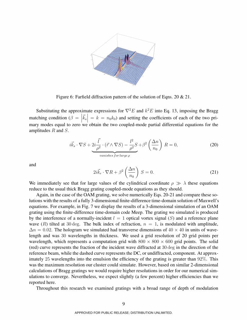
Figure 6: Farfield diffraction pattern of the solution of Eqns. 20 & 21.
Substituting the approximate expressions for ∇2E and k2E into Eq. 13, imposing the Braggmatching condition (� =
∣∣∣ks∣∣∣ = k = n0k0) and setting the coefficients of each of the two pri-
mary modes equal to zero we obtain the two coupled-mode partial differential equations for theamplitudes R and S.
iks ⋅ ∇S + 2il
�2⋅ (r ∧∇S)− l2
�2S
︸ ︷︷ ︸vanisℎes for large �
+�2
(Δn
n0
)R = 0, (20)
and
2ikr ⋅ ∇R + �2
(Δn
n0
)S = 0. (21)
We immediately see that for large values of the cylindrical coordinate � ≫ � these equationsreduce to the usual thick Bragg grating coupled-mode equations as they should.
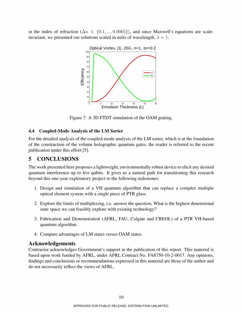
Again, in the case of the OAM grating, we solve numerically Eqs. 20-21 and compare these so-lutions with the results of a fully 3-dimensional finite-difference time-domain solution of Maxwell’sequations. For example, in Fig. 7 we display the results of a 3-dimensional simulation of an OAMgrating using the finite-difference time-domain code Meep. The grating we simulated is producedby the interference of a normally-incident l = 1 optical vortex signal (S) and a reference planewave (R) tilted at 30 deg. The bulk index of refraction, n = 1, is modulated with amplitude,Δn = 0.02. The hologram we simulated had transverse dimensions of 40 × 40 in units of wave-length and was 30 wavelengths in thickness. We used a grid resolution of 20 grid points perwavelength, which represents a computation grid with 800 × 800 × 600 grid points. The solid(red) curve represents the fraction of the incident wave diffracted at 30 deg in the direction of thereference beam, while the dashed curve represents the DC, or undiffracted, component. At approx-imately 25 wavelengths into the emulsion the efficiency of the grating is greater than 92%. Thiswas the maximum resolution our cluster could simulate. However, based on similar 2-dimensionalcalculations of Bragg gratings we would require higher resolutions in order for our numerical sim-ulations to converge. Nevertheless, we expect slightly (a few percent) higher efficiencies than wereported here.
Throughout this research we examined gratings with a broad range of depth of modulation
9
APPROVED FOR PUBLIC RELEASE; DISTRIBUTION UNLIMITED.
in the index of refraction (Δn ∈ {0.1, ..., 0.0005}), and since Maxwell’s equations are scale-invariant, we presented our solutions scaled in units of wavelength, � = 1.
0 5 10 15 20 25 300
10
20
30
40
50
60
70
80
90
100Optical Vortex, |1 , 20/ , n=1, n=0.2
Emulsion Thickness ( )
Effic
ienc
y
|1|0
Figure 7: A 3D FTDT simulation of the OAM grating.
4.4 Coupled-Mode Analysis of the LM Sorter
For the detailed analysis of the coupled-mode analysis of the LM sorter, which is at the foundationof the construction of the volume holographic quantum gates, the reader is referred to the recentpublication under this effort [5].
5 CONCLUSIONSThe work presented here proposes a lightweight, environmentally robust device to elicit any desiredquantum interference up to five qubits. It gives us a natural path for transitioning this researchbeyond this one-year exploratory project to the following milestones:
1. Design and simulation of a VH quantum algorithm that can replace a complex multipleoptical element system with a single piece of PTR glass.
2. Explore the limits of multiplexing, i.e. answer the question, What is the highest dimensionalstate space we can feasibly explore with existing technology?
3. Fabrication and Demonstration (AFRL, FAU, Colgate and CREOL) of a PTR VH-basedquantum algorithm.
4. Compare advantages of LM states verses OAM states.
AcknowledgementsContractor acknowledges Government’s support in the publication of this report. This material isbased upon work funded by AFRL, under AFRL Contract No. FA8750-10-2-0017. Any opinions,findings and conclusions or recommendations expressed in this material are those of the author anddo not necessarily reflect the views of AFRL.
10
APPROVED FOR PUBLIC RELEASE; DISTRIBUTION UNLIMITED.
6 LIST OF SYMBOLS, ABBREVIATIONS AND ACRONYMSAFRL Air Force Research LaboratoryBER Bit Error RateCNOT Controlled NotCREOL The College of Optics & PhotonicsCSQC Cluster State Quantum ComputingFAU Florida Atlantic UniversityFDTD Finite Difference Time DomainGP/GPU General Purpose Graphical Processing UnitsHPC High Performance ComputingLM Linear MomentumLOCQ Linear Optical Quantum ComputerMeep Massachusetts Institute of Technology’s Electromagnetic Equation Propagation CodeMIT Massachusetts Institute of TechnologyMPI Message Passing InterfaceMUB Mutually Unbiased BasisOAM Orbital Angular MomentumOWQC One-Way Quantum ComputerPI Principle InvestigatorPTR Photo-Thermal RefractiveQIP Quantum Information ProcessingQCM Quantum Circuit ModelQKD Quantum Key Distributionqubit Quantum bitqudit Quantum d-level systemRI Information DirectorateRITC Emerging Computing TechnologySLM Spatial Light ModulatorSPIE International Society for Optics and PhotonicsUG UndergraduateUS United StatesVH Volume HologramV&V Verification and Visualization
11
APPROVED FOR PUBLIC RELEASE; DISTRIBUTION UNLIMITED.
7 REFERENCES1. M. A. Nielsen and I. L. Chuang. Quantum computation and quantum information (Cam-
bridge University Press, Cambridge, 2000) ch.4.
2. Knill, R. Laflamme and G. J. Milburn, A scheme for efficient quantum computation withlinear optics,” Nature 409, 46, 2001.
3. R. Raussendorf and H. J. Briegel, Phys. Rev. Lett., 86 (22), 51885191, 2001.
4. M. A. Nielsen, “Cluster-State Quantum Computation,” arXiv:quant-ph/0504097v2 (2005).
5. W. A. Miler, Efficient photon sorter in a high-dimensional state space,” Quantum Information& Computation, Vol 11, No. 3 & 4 (2011) 0313-0325.
6. M. T. Gruneisen and W. A. Miller, R. C. Dymale and A. M. Sweiti, Holographic generationof complex fields with spatial light modulators: application to quantum key distribution,Applied Optics 47 (4), (2008) pp. A32-A42.
7. I. Ciapurin, L. B. Glebov and V. M. Smirnov, Opt. Eng. 45, 015802 (2006).
8. L. Allen et. al., Phys. Rev. A45, 8185 (1992).
9. Optical Angular Momentum, eds. L. Allen, S. M. Barnett, and M. J. Padgett (IOP PublishingLtd., London, 2003).
10. W. A. Miller and J. A. Wheeler, Proc. Int. Symp. Foundations of Quantum Mechanics inthe Light of New Technology, eds. S. Kamefuchi, et al. (Physical Society of Japan, Tokyo,1984) 140-152.
11. A. Mair et. al., Nature (London) 412, 313 (2001).
12. S. S. R. Oemrawsingh et. al., Phys. Rev. Lett 92, 217901 (2004).
13. G. Molina-Terriza, J. P. Torres and L. Torner, Phys. Rev. Lett. 88, 013601 (2001).
14. M. G. Moharam, T. K. Gaylord and R. Magunsson, J. Opt. Soc. Am. 70 (1980) pp.300-304.
15. S.-D. Wu, T. K. Gaylord, E. N. Glytsis and Y.-M. Wu, J. Opt. Soc. Am. A22 (2005)pp.1293-1303.
16. M.G. Moharam, T. K. Gaylord and R. Magnusson, “Bragg difraction of finite beams by thickgratings,” J. Opt. Soc. Am. 70 (1980) p. 300.
12
APPROVED FOR PUBLIC RELEASE; DISTRIBUTION UNLIMITED.