29
Quality You Can Trust Since 1886... From North America’s Largest Roofing Manufacturer ™ Florida Building Code Online Product Approval Information Sheet Updated: 6/09
Quality You Can Trust Since 1886...From North America’s Largest Roofing Manufacturer ™
Florida Building Code OnlineProduct Approval
Information Sheet
Updated: 6/09
BCI S Hom e Log I n User Regist rat ion Hot Topics Subm it Surcharge Stats & Facts Publicat ions FBC Staff BCI S Site Map Links Search
Product Approval USER: Public User
Product Approval Menu > Product or Applicat ion Search > Applicat ion List > Applicat ion Deta il
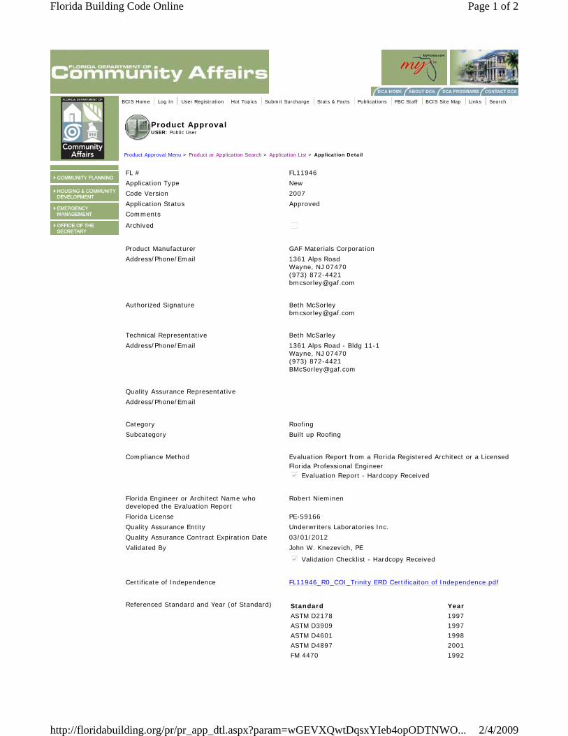
FL # FL11946
Applicat ion Type New
Code Version 2007
Applicat ion Status Approved
Com m ents
Archived
Product Manufacturer GAF Mater ials Corporat ion
Address/ Phone/ Em ail 1361 Alps Road Wayne, NJ 07470 (973) 872-4421 bm [email protected]
Author ized Signature Beth McSorley
Technical Representat ive Beth McSarley
Address/ Phone/ Em ail 1361 Alps Road - Bldg 11-1 Wayne, NJ 07470 (973) 872-4421 [email protected]
Qualit y Assurance Representat ive
Address/ Phone/ Em ail
Category Roofing
Subcategory Built up Roofing
Com pliance Method Evaluat ion Report from a Flor ida Registered Architect or a Licensed
Flor ida Professional Engineer Evaluat ion Report - Hardcopy Received
Flor ida Engineer or Architect Nam e who developed the Evaluat ion Report
Robert Niem inen
Flor ida License PE-59166
Quality Assurance Ent ity Underwriters Laborator ies I nc.
Qualit y Assurance Cont ract Expirat ion Date 03/ 01/ 2012
Validated By John W. Knezevich, PE
Validat ion Checklist - Hardcopy Received
Cert ificate of I ndependence FL11946_R0_COI _Trinity ERD Cert if icaiton of I ndependence.pdf
Referenced Standard and Year (of Standard) Standard Year
ASTM D2178 1997
ASTM D3909 1997
ASTM D4601 1998
ASTM D4897 2001
FM 4470 1992
Page 1 of 2Florida Building Code Online
2/4/2009http://floridabuilding.org/pr/pr_app_dtl.aspx?param=wGEVXQwtDqsxYIeb4opODTNWO...
Equivalence of Product Standards Cert if ied By
Sect ions from the Code
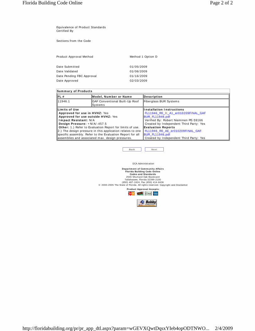
Product Approval Method Method 1 Opt ion D
Date Subm it ted 01/ 05/ 2009
Date Validated 01/ 06/ 2009
Date Pending FBC Approval 01/ 16/ 2009
Date Approved 02/ 03/ 2009
Sum m ary of Products
FL # Model, Num ber or Nam e Descr ipt ion
11946.1 GAF Convent ional Built -Up Roof System s
Fiberglass BUR System s
Lim its of Use Approved for use in HVHZ: Yes Approved for use outside HVHZ: Yes I m pact Resistant : N/ A Design Pressure: + N/ A/ -457.5 Other : 1.) Refer to Evaluat ion Report for lim its of use. 2.) The design pressure in this applicat ion relates to one specific assem bly. Refer to the Evaluat ion Report for all assem blies and associated m ax. design pressures.
I nsta lla t ion I nst ruct ions FL11946_R0_I I _A1_er010209FI NAL_GAF BUR_FL11946.pdf Verified By: Robert Niem inen PE-59166 Created by I ndependent Third Party: Yes Evaluat ion Repor ts FL11946_R0_AE_er010209FI NAL_GAF BUR_FL11946.pdf Created by I ndependent Third Party: Yes
Back Next
DCA Adm inist rat ion
Departm ent of Com m unity Affa irs Flor ida Building Code Online
Codes and Standards 2555 Shum ard Oak Boulevard
Tallahassee, Flor ida 32399-2100 (850) 487-1824, Fax (850) 414-8436
© 2000-2005 The State of Flor ida. All r ights reserved. Copyright and Disclaim er
Product Approva l Accepts:
Page 2 of 2Florida Building Code Online
2/4/2009http://floridabuilding.org/pr/pr_app_dtl.aspx?param=wGEVXQwtDqsxYIeb4opODTNWO...
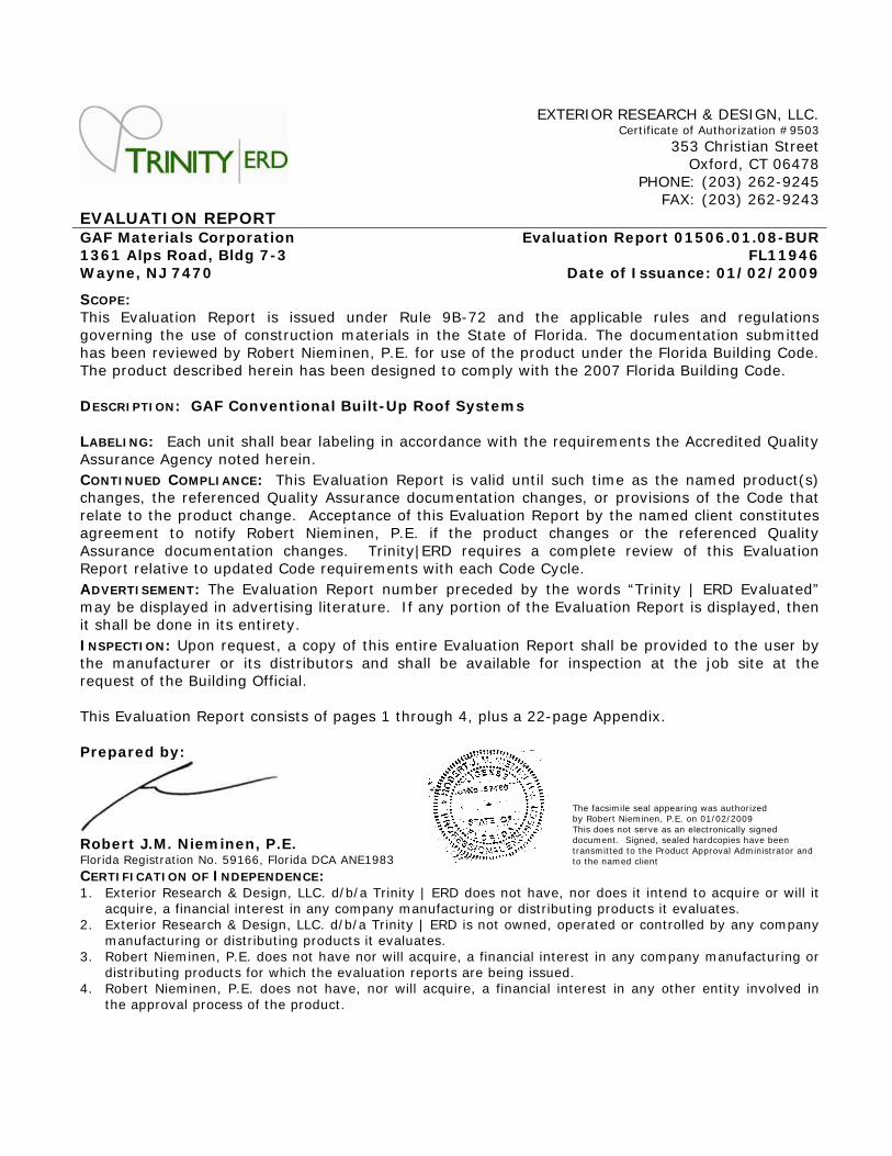
EXTERI OR RESEARCH & DESI GN, LLC. Cert ificate of Author izat ion # 9503
353 Christ ian St reet Oxford, CT 06478 PHONE: (203) 262-9245 FAX: (203) 262-9243 EVALUATI ON REPORT GAF Mater ia ls Corporat ion 1 3 6 1 Alps Road, Bldg 7 - 3 W ayne, NJ 7 4 7 0
Evaluat ion Repor t 0 1 5 0 6 .0 1 .0 8 - BUR FL1 1 9 4 6
Date of I ssuance: 0 1 / 0 2 / 2 0 0 9
SCOPE: This Evaluat ion Report is issued under Rule 9B-72 and the applicable rules and regulat ions governing the use of const ruct ion m aterials in the State of Flor ida. The documentat ion subm it ted has been reviewed by Robert Niem inen, P.E. for use of the product under the Florida Building Code. The product described herein has been designed to comply with the 2007 Florida Building Code. DESCRI PTI ON : GAF Convent ional Bu ilt - Up Roof System s LABELI NG : Each unit shall bear labeling in accordance with the requirements the Accredited Qualit y Assurance Agency noted herein. CONTI NUED COMPLI ANCE : This Evaluat ion Report is valid unt il such t ime as the named product (s) changes, the referenced Quality Assurance docum entat ion changes, or provisions of the Code that relate to the product change. Acceptance of this Evaluat ion Report by the nam ed client const itutes agreem ent to not ify Robert Niem inen, P.E. if the product changes or the referenced Quality Assurance docum entat ion changes. Tr inity| ERD requires a com plete review of this Evaluat ion Report relat ive to updated Code requirements with each Code Cycle. ADVERTI SEMENT: The Evaluat ion Report num ber preceded by the words “Trinity | ERD Evaluated” m ay be displayed in advert ising literature. I f any port ion of the Evaluat ion Report is displayed, then it shall be done in its ent irety. I NSPECTI ON : Upon request , a copy of this ent ire Evaluat ion Report shall be provided to the user by the m anufacturer or its dist r ibutors and shall be available for inspect ion at the job site at the request of the Building Official. This Evaluat ion Report consists of pages 1 through 4, plus a 22-page Appendix. Prepared by:
Robert J.M. N iem inen, P.E. Flor ida Regist rat ion No. 59166, Flor ida DCA ANE1983
The facsim ile seal appearing was author ized by Robert Niem inen, P.E. on 01/ 02/ 2009 This does not serve as an elect ronically signed document . Signed, sealed hardcopies have been t ransm it ted to the Product Approval Adm inist rator and to the named client
CERTI FI CATI ON OF I NDEPENDENCE: 1. Exter ior Research & Design, LLC. d/ b/ a Trinity | ERD does not have, nor does it intend to acquire or will it
acquire, a financial interest in any company m anufacturing or dist r ibut ing products it evaluates. 2. Exter ior Research & Design, LLC. d/ b/ a Trinity | ERD is not owned, operated or cont rolled by any com pany
m anufacturing or dist r ibut ing products it evaluates. 3. Robert Niem inen, P.E. does not have nor will acquire, a financial interest in any com pany m anufacturing or
dist r ibut ing products for which the evaluat ion reports are being issued. 4. Robert Niem inen, P.E. does not have, nor will acquire, a financial interest in any other ent ity involved in
the approval process of the product .
Ex ter ior Research and Design, LLC. Eva luat ion Repo r t 0 1 5 0 6 .0 1 .0 9 - BUR Cert ificate of Authorizat ion # 9 5 0 3 FL1 1 9 4 6 Date of I ssuance: 0 1 / 0 2 / 2 0 0 9 Page 2 of 4
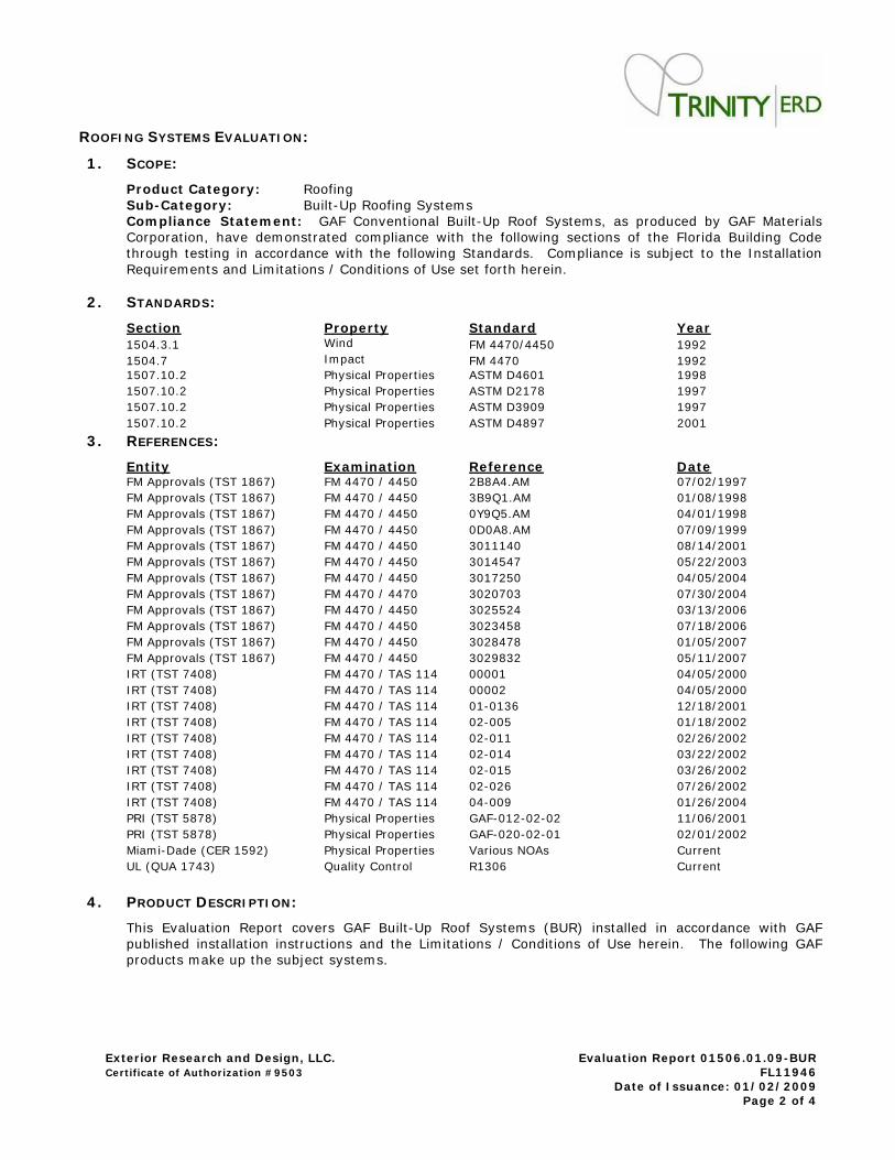
ROOFI NG SYSTEMS EVALUATI ON :
1 . SCOPE:
Product Category: Roofing Sub- Category: Built -Up Roofing System s Com pliance Statem ent : GAF Convent ional Built -Up Roof System s, as produced by GAF Materials Corporat ion, have dem onst rated com pliance with the following sect ions of the Flor ida Building Code through test ing in accordance with the following Standards. Com pliance is subject to the I nstallat ion Requirem ents and Lim itat ions / Condit ions of Use set forth herein.
2 . STANDARDS :
Sect ion Proper ty Standard Year 1504.3.1 Wind FM 4470/ 4450 1992 1504.7 I m pact FM 4470 1992 1507.10.2 Physical Propert ies ASTM D4601 1998
1507.10.2 Physical Propert ies ASTM D2178 1997
1507.10.2 Physical Propert ies ASTM D3909 1997
1507.10.2 Physical Propert ies ASTM D4897 2001
3 . REFERENCES:
Ent it y Exam inat ion Reference Date FM Approvals (TST 1867) FM 4470 / 4450 2B8A4.AM 07/ 02/ 1997
FM Approvals (TST 1867) FM 4470 / 4450 3B9Q1.AM 01/ 08/ 1998
FM Approvals (TST 1867) FM 4470 / 4450 0Y9Q5.AM 04/ 01/ 1998
FM Approvals (TST 1867) FM 4470 / 4450 0D0A8.AM 07/ 09/ 1999
FM Approvals (TST 1867) FM 4470 / 4450 3011140 08/ 14/ 2001
FM Approvals (TST 1867) FM 4470 / 4450 3014547 05/ 22/ 2003
FM Approvals (TST 1867) FM 4470 / 4450 3017250 04/ 05/ 2004
FM Approvals (TST 1867) FM 4470 / 4470 3020703 07/ 30/ 2004
FM Approvals (TST 1867) FM 4470 / 4450 3025524 03/ 13/ 2006
FM Approvals (TST 1867) FM 4470 / 4450 3023458 07/ 18/ 2006
FM Approvals (TST 1867) FM 4470 / 4450 3028478 01/ 05/ 2007
FM Approvals (TST 1867) FM 4470 / 4450 3029832 05/ 11/ 2007
I RT (TST 7408) FM 4470 / TAS 114 00001 04/ 05/ 2000
I RT (TST 7408) FM 4470 / TAS 114 00002 04/ 05/ 2000
I RT (TST 7408) FM 4470 / TAS 114 01-0136 12/ 18/ 2001
I RT (TST 7408) FM 4470 / TAS 114 02-005 01/ 18/ 2002
I RT (TST 7408) FM 4470 / TAS 114 02-011 02/ 26/ 2002
I RT (TST 7408) FM 4470 / TAS 114 02-014 03/ 22/ 2002
I RT (TST 7408) FM 4470 / TAS 114 02-015 03/ 26/ 2002
I RT (TST 7408) FM 4470 / TAS 114 02-026 07/ 26/ 2002
I RT (TST 7408) FM 4470 / TAS 114 04-009 01/ 26/ 2004
PRI (TST 5878) Physical Propert ies GAF-012-02-02 11/ 06/ 2001
PRI (TST 5878) Physical Propert ies GAF-020-02-01 02/ 01/ 2002
Miam i-Dade (CER 1592) Physical Propert ies Various NOAs Current
UL (QUA 1743) Quality Cont rol R1306 Current
4 . PRODUCT DESCRI PTI ON :
This Evaluat ion Report covers GAF Built -Up Roof System s (BUR) installed in accordance with GAF published installat ion inst ruct ions and the Lim itat ions / Condit ions of Use herein. The following GAF products m ake up the subject system s.
Ex ter ior Research and Design, LLC. Eva luat ion Repo r t 0 1 5 0 6 .0 1 .0 9 - BUR Cert ificate of Authorizat ion # 9 5 0 3 FL1 1 9 4 6 Date of I ssuance: 0 1 / 0 2 / 2 0 0 9 Page 3 of 4
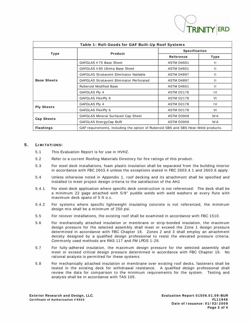
Table 1 : Roll- Goods for GAF Built - Up Roof System s
Specif ica t ion
Type Product
Reference Type
GAFGLAS # 75 Base Sheet ASTM D4601 I I
GAFGLAS # 80 Ult ima Base Sheet ASTM D4601 I I
GAFGLAS Stratavent Elim inator Nailable ASTM D4897 I I
GAFGLAS Stratavent Elim inator Perforated ASTM D4897 I I
Ruberoid Modified Base ASTM D4601 I I
GAFGLAS Ply 4 ASTM D2178 I V
Base Sheets
GAFGLAS FlexPly 6 ASTM D2178 VI
GAFGLAS Ply 4 ASTM D2178 I V
Ply Sheets
GAFGLAS FlexPly 6 ASTM D2178 VI
GAFGLAS Mineral Surfaced Cap Sheet ASTM D3909 N/ A
Cap Sheets
GAFGLAS EnergyCap BUR ASTM D3909 N/ A
Flashings GAF requirem ents, including the opt ion of Ruberoid SBS and SBS Heat -Weld products.
5 . L I MI TATI ONS:
5.1 This Evaluat ion Report is for use in HVHZ.
5.2 Refer to a current Roofing Materials Directory for fire rat ings of this product .
5.3 For steel deck installat ions, foam plast ic insulat ion shall be separated from the building interior in accordance with FBC 2603.4 unless the except ions stated in FBC 2603.4.1 and 2603.6 apply.
5.4 Unless otherwise noted in Appendix 1, roof decking and its at tachm ent shall be specified and installed to m eet project design cr iter ia to the sat isfact ion of the AHJ.
5.4.1 For steel deck applicat ion where specific deck const ruct ion is not referenced: The deck shall be a m inim um 22 gage at tached with 5/ 8” puddle welds with weld washers at every flute with m axim um deck spans of 5 ft o.c.
5.4.2 For systems where specific lightweight insulat ing concrete is not referenced, the m inim um design m ix shall be a m inim um of 250 psi.
5.5 For recover installat ions, the exist ing roof shall be exam ined in accordance with FBC 1510.
5.6 For m echanically at tached insulat ion or m em brane or st r ip-bonded insulat ion, the m axim um design pressure for the selected assembly shall meet or exceed the Zone 1 design pressure determ ined in accordance with FBC Chapter 16. Zones 2 and 3 shall em ploy an at tachm ent density designed by a qualified design professional to resist the elevated pressure cr iter ia. Com m only used methods are RAS 117 and FM LPDS 1-29.
5.7 For fully-adhered insulat ion, the m axim um design pressure for the selected assem bly shall meet or exceed cr it ical design pressure determ ined in accordance with FBC Chapter 16. No rat ional analysis is perm it ted for these system s
5.8 For m echanically at tached insulat ion or m em brane over exist ing roof decks, fasteners shall be tested in the exist ing deck for withdrawal resistance. A qualified design professional shall review the data for com parison to the m inim um requirem ents for the system . Test ing and analysis shall be in accordance with TAS 105.
Ex ter ior Research and Design, LLC. Eva luat ion Repo r t 0 1 5 0 6 .0 1 .0 9 - BUR Cert ificate of Authorizat ion # 9 5 0 3 FL1 1 9 4 6 Date of I ssuance: 0 1 / 0 2 / 2 0 0 9 Page 4 of 4
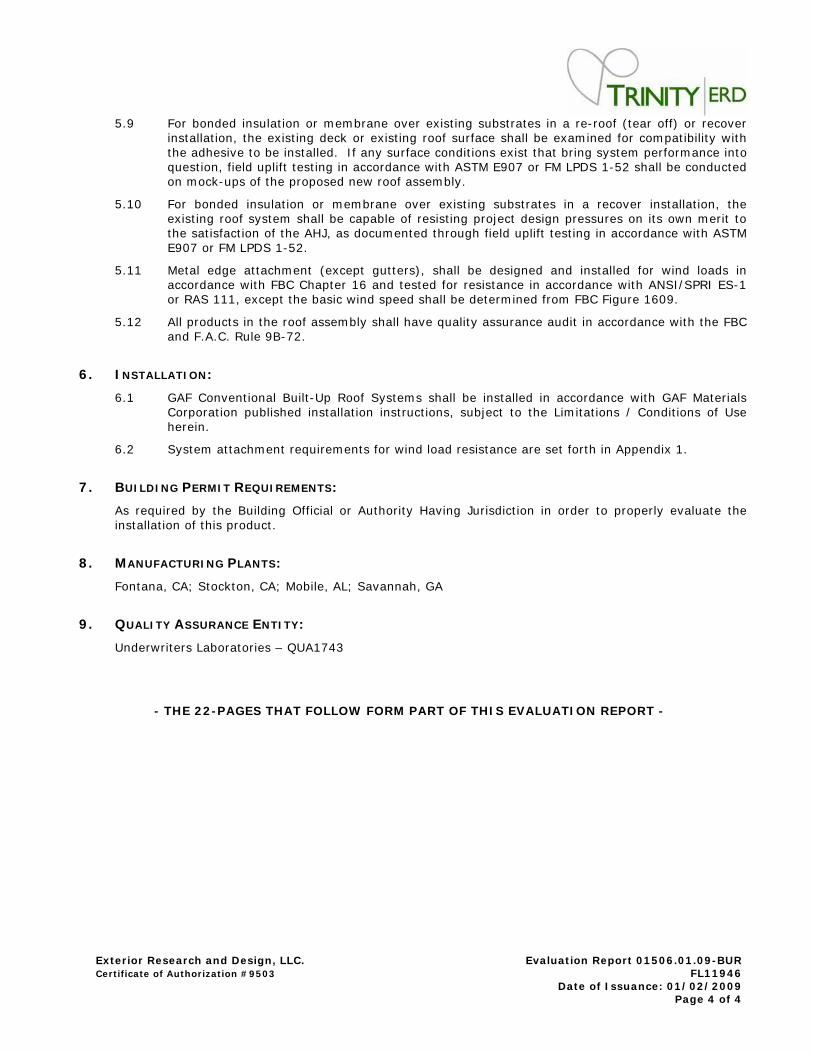
5.9 For bonded insulat ion or m em brane over exist ing subst rates in a re- roof ( tear off) or recover installat ion, the exist ing deck or exist ing roof surface shall be exam ined for com pat ibilit y with the adhesive to be installed. I f any surface condit ions exist that br ing system perform ance into quest ion, field uplift test ing in accordance with ASTM E907 or FM LPDS 1-52 shall be conducted on m ock-ups of the proposed new roof assem bly.
5.10 For bonded insulat ion or m em brane over exist ing subst rates in a recover installat ion, the exist ing roof system shall be capable of resist ing project design pressures on its own merit to the sat isfact ion of the AHJ, as docum ented through field uplift test ing in accordance with ASTM E907 or FM LPDS 1-52.
5.11 Metal edge at tachment (except gut ters) , shall be designed and installed for wind loads in accordance with FBC Chapter 16 and tested for resistance in accordance with ANSI / SPRI ES-1 or RAS 111, except the basic wind speed shall be determ ined from FBC Figure 1609.
5.12 All products in the roof assem bly shall have quality assurance audit in accordance with the FBC and F.A.C. Rule 9B-72.
6 . I NSTALLATI ON :
6.1 GAF Convent ional Built -Up Roof System s shall be installed in accordance with GAF Materials Corporat ion published installat ion inst ruct ions, subject to the Lim itat ions / Condit ions of Use herein.
6.2 System at tachm ent requirem ents for wind load resistance are set forth in Appendix 1.
7 . BUI LDI NG PERMI T REQUI REMENTS:
As required by the Building Official or Authority Having Jurisdict ion in order to properly evaluate the installat ion of this product .
8 . MANUFACTURI NG PLANTS :
Fontana, CA; Stockton, CA; Mobile, AL; Savannah, GA
9 . QUALI TY ASSURANCE ENTI TY:
Underwriters Laboratories – QUA1743
- THE 2 2 - PAGES THAT FOLLOW FORM PART OF THI S EVALUATI ON REPORT -
Exterior Research and Design, LLC. d/ b/ a Trinity | ERD Evaluat ion Report 01506.01.09-BUR for FL11946 Cert ificate of Authorizat ion # 9503 Date of I ssuance: 01/ 02/ 2009 Prepared by: Robert Niem inen, PE-59166 Appendix 1, Page 1 of 22
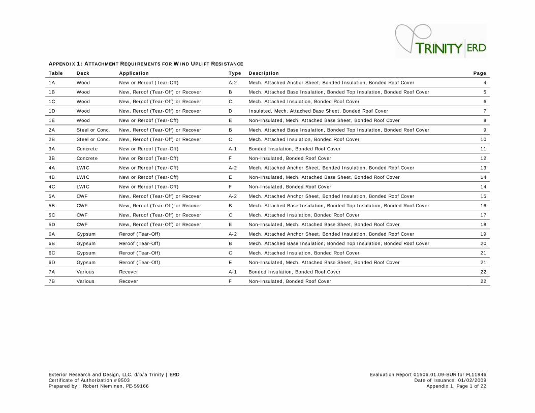
APPENDI X 1 : ATTACHMENT REQUI REMENTS FOR W I ND UPLI FT RESI STANCE
Table Deck Applicat ion Type Descr ipt ion Page
1A Wood New or Reroof (Tear-Off) A-2 Mech. At tached Anchor Sheet , Bonded I nsulat ion, Bonded Roof Cover 4
1B Wood New, Reroof (Tear-Off) or Recover B Mech. At tached Base I nsulat ion, Bonded Top I nsulat ion, Bonded Roof Cover 5
1C Wood New, Reroof (Tear-Off) or Recover C Mech. At tached I nsulat ion, Bonded Roof Cover 6
1D Wood New, Reroof (Tear-Off) or Recover D I nsulated, Mech. At tached Base Sheet , Bonded Roof Cover 7
1E Wood New or Reroof (Tear-Off) E Non- I nsulated, Mech. At tached Base Sheet , Bonded Roof Cover 8
2A Steel or Conc. New, Reroof (Tear-Off) or Recover B Mech. At tached Base I nsulat ion, Bonded Top I nsulat ion, Bonded Roof Cover 9
2B Steel or Conc. New, Reroof (Tear-Off) or Recover C Mech. At tached I nsulat ion, Bonded Roof Cover 10
3A Concrete New or Reroof (Tear-Off) A-1 Bonded I nsulat ion, Bonded Roof Cover 11
3B Concrete New or Reroof (Tear-Off) F Non- I nsulated, Bonded Roof Cover 12
4A LWI C New or Reroof (Tear-Off) A-2 Mech. At tached Anchor Sheet , Bonded I nsulat ion, Bonded Roof Cover 13
4B LWI C New or Reroof (Tear-Off) E Non- I nsulated, Mech. At tached Base Sheet , Bonded Roof Cover 14
4C LWI C New or Reroof (Tear-Off) F Non- I nsulated, Bonded Roof Cover 14
5A CWF New, Reroof (Tear-Off) or Recover A-2 Mech. At tached Anchor Sheet , Bonded I nsulat ion, Bonded Roof Cover 15
5B CWF New, Reroof (Tear-Off) or Recover B Mech. At tached Base I nsulat ion, Bonded Top I nsulat ion, Bonded Roof Cover 16
5C CWF New, Reroof (Tear-Off) or Recover C Mech. At tached I nsulat ion, Bonded Roof Cover 17
5D CWF New, Reroof (Tear-Off) or Recover E Non- I nsulated, Mech. At tached Base Sheet , Bonded Roof Cover 18
6A Gypsum Reroof (Tear-Off) A-2 Mech. At tached Anchor Sheet , Bonded I nsulat ion, Bonded Roof Cover 19
6B Gypsum Reroof (Tear-Off) B Mech. At tached Base I nsulat ion, Bonded Top I nsulat ion, Bonded Roof Cover 20
6C Gypsum Reroof (Tear-Off) C Mech. At tached I nsulat ion, Bonded Roof Cover 21
6D Gypsum Reroof (Tear-Off) E Non- I nsulated, Mech. At tached Base Sheet , Bonded Roof Cover 21
7A Various Recover A-1 Bonded I nsulat ion, Bonded Roof Cover 22
7B Various Recover F Non- I nsulated, Bonded Roof Cover 22
Exterior Research and Design, LLC. d/ b/ a Trinity | ERD Evaluat ion Report 01506.01.09-BUR for FL11946 Cert ificate of Authorizat ion # 9503 Date of I ssuance: 01/ 02/ 2009 Prepared by: Robert Niem inen, PE-59166 Appendix 1, Page 2 of 22
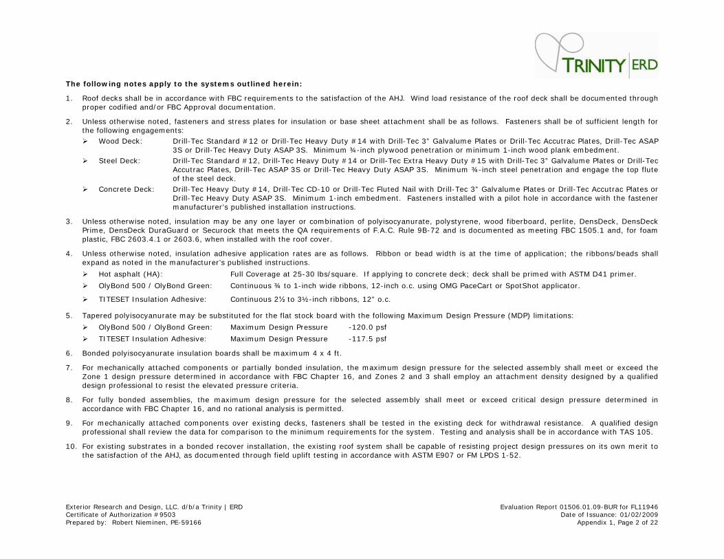
The follow ing notes apply t o th e system s out lined here in:
1. Roof decks shall be in accordance with FBC requirem ents to the sat isfact ion of the AHJ. Wind load resistance of the roof deck shall be docum ented through proper codif ied and/ or FBC Approval docum entat ion.
2. Unless otherwise noted, fasteners and st ress plates for insulat ion or base sheet at tachm ent shall be as follows. Fasteners shall be of suff icient length for the following engagem ents:
Ü Wood Deck: Drill-Tec Standard # 12 or Drill-Tec Heavy Duty # 14 with Drill-Tec 3” Galvalum e Plates or Drill-Tec Accut rac Plates, Drill-Tec ASAP 3S or Drill-Tec Heavy Duty ASAP 3S. Minim um ¾- inch plywood penet rat ion or m inimum 1- inch wood plank embedment .
Ü Steel Deck: Drill-Tec Standard # 12, Drill-Tec Heavy Duty # 14 or Drill-Tec Ext ra Heavy Duty # 15 with Dr ill-Tec 3” Galvalume Plates or Dr ill-Tec Accut rac Plates, Drill-Tec ASAP 3S or Drill-Tec Heavy Duty ASAP 3S. Minim um ¾- inch steel penet rat ion and engage the top flute of the steel deck.
Ü Concrete Deck: Drill-Tec Heavy Duty # 14, Drill-Tec CD-10 or Drill-Tec Fluted Nail with Drill-Tec 3” Galvalume Plates or Drill-Tec Accut rac Plates or Drill-Tec Heavy Duty ASAP 3S. Minim um 1- inch embedm ent . Fasteners installed with a pilot hole in accordance with the fastener manufacturer ’s published installat ion inst ruct ions.
3. Unless otherwise noted, insulat ion may be any one layer or combinat ion of polyisocyanurate, polystyrene, wood fiberboard, per lite, DensDeck, DensDeck Prime, DensDeck DuraGuard or Securock that meets the QA requirements of F.A.C. Rule 9B-72 and is docum ented as m eet ing FBC 1505.1 and, for foam plast ic, FBC 2603.4.1 or 2603.6, when installed with the roof cover.
4. Unless otherwise noted, insulat ion adhesive applicat ion rates are as follows. Ribbon or bead width is at the t im e of applicat ion; the r ibbons/ beads shall expand as noted in the m anufacturer’s published inst ruct ions.
Ü Hot asphalt (HA) : Full Coverage at 25-30 lbs/ square. I f applying to concrete deck; deck shall be pr im ed with ASTM D41 prim er.
Ü OlyBond 500 / OlyBond Green: Cont inuous ¾ to 1- inch wide r ibbons, 12- inch o.c. using OMG PaceCart or SpotShot applicator .
Ü TI TESET I nsulat ion Adhesive: Cont inuous 2½ to 3½- inch r ibbons, 12” o.c.
5. Tapered polyisocyanurate m ay be subst ituted for the flat stock board with the following Maxim um Design Pressure (MDP) lim itat ions:
Ü OlyBond 500 / OlyBond Green: Maximum Design Pressure -120.0 psf
Ü TI TESET I nsulat ion Adhesive: Maximum Design Pressure -117.5 psf
6. Bonded polyisocyanurate insulat ion boards shall be maxim um 4 x 4 ft .
7. For m echanically at tached components or part ially bonded insulat ion, the m aximum design pressure for the selected assembly shall meet or exceed the Zone 1 design pressure determ ined in accordance with FBC Chapter 16, and Zones 2 and 3 shall employ an at tachm ent density designed by a qualif ied design professional to resist the elevated pressure cr iter ia.
8. For fully bonded assem blies, the m axim um design pressure for the selected assem bly shall m eet or exceed cr it ical design pressure determ ined in accordance with FBC Chapter 16, and no rat ional analysis is perm it ted.
9. For m echanically at tached com ponents over exist ing decks, fasteners shall be tested in the exist ing deck for withdrawal resistance. A qualif ied design professional shall review the data for com parison to the m inimum requirements for the system . Test ing and analysis shall be in accordance with TAS 105.
10. For exist ing subst rates in a bonded recover installat ion, the exist ing roof system shall be capable of resist ing project design pressures on it s own mer it to the sat isfact ion of the AHJ, as docum ented through field uplift test ing in accordance with ASTM E907 or FM LPDS 1-52.
Exterior Research and Design, LLC. d/ b/ a Trinity | ERD Evaluat ion Report 01506.01.09-BUR for FL11946 Cert ificate of Authorizat ion # 9503 Date of I ssuance: 01/ 02/ 2009 Prepared by: Robert Niem inen, PE-59166 Appendix 1, Page 3 of 22
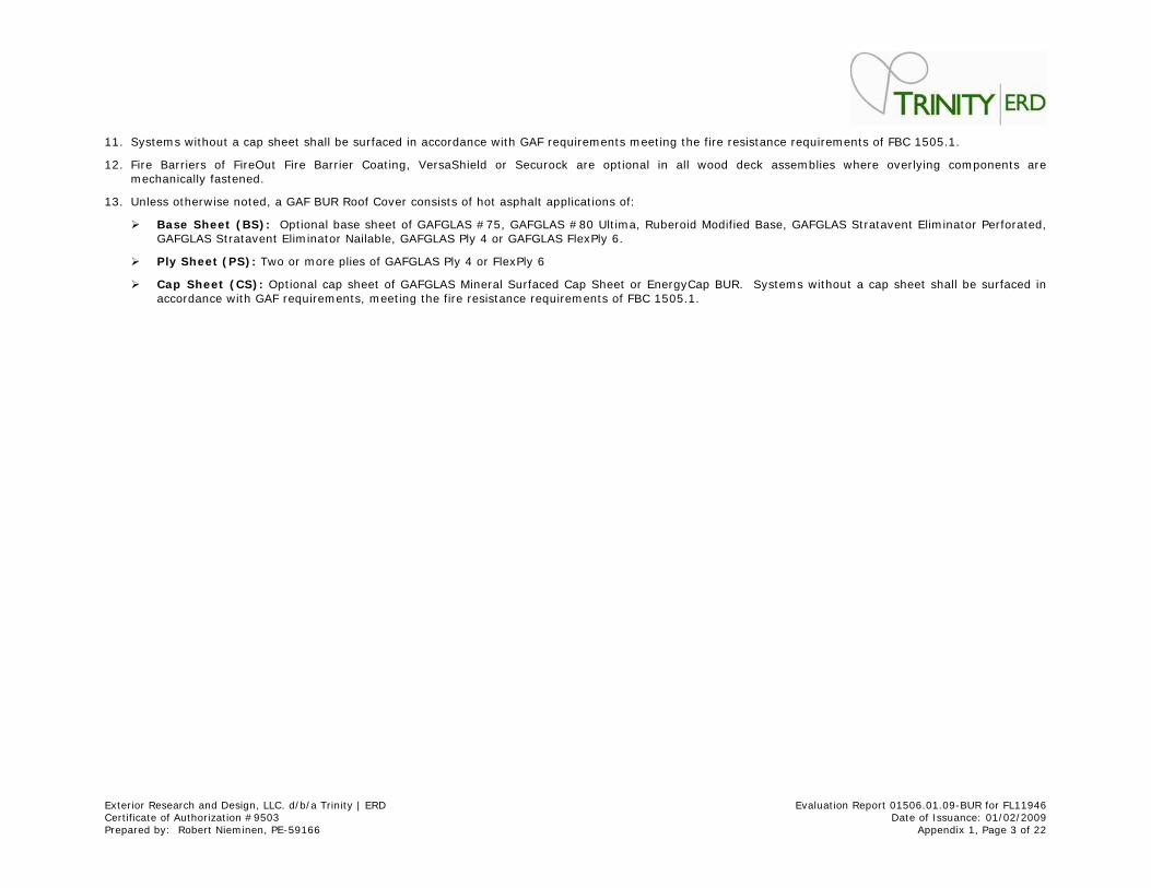
11. System s without a cap sheet shall be surfaced in accordance with GAF requirements m eet ing the fire resistance requirem ents of FBC 1505.1.
12. Fire Barr iers of FireOut Fire Barr ier Coat ing, VersaShield or Securock are opt ional in all wood deck assem blies where overlying components are m echanically fastened.
13. Unless otherwise noted, a GAF BUR Roof Cover consists of hot asphalt applicat ions of:
Ü Base Sheet ( BS) : Opt ional base sheet of GAFGLAS # 75, GAFGLAS # 80 Ult ima, Ruberoid Modified Base, GAFGLAS St ratavent Elim inator Perforated, GAFGLAS Stratavent Elim inator Nailable, GAFGLAS Ply 4 or GAFGLAS FlexPly 6.
Ü Ply Sheet ( PS) : Two or m ore plies of GAFGLAS Ply 4 or FlexPly 6
Ü Cap Sheet ( CS) : Opt ional cap sheet of GAFGLAS Mineral Surfaced Cap Sheet or EnergyCap BUR. Systems without a cap sheet shall be surfaced in accordance with GAF requirements, m eet ing the fire resistance requirem ents of FBC 1505.1.
Exterior Research and Design, LLC. d/ b/ a Trinity | ERD Evaluat ion Report 01506.01.09-BUR for FL11946 Cert ificate of Authorizat ion # 9503 Date of I ssuance: 01/ 02/ 2009 Prepared by: Robert Niem inen, PE-59166 Appendix 1, Page 4 of 22
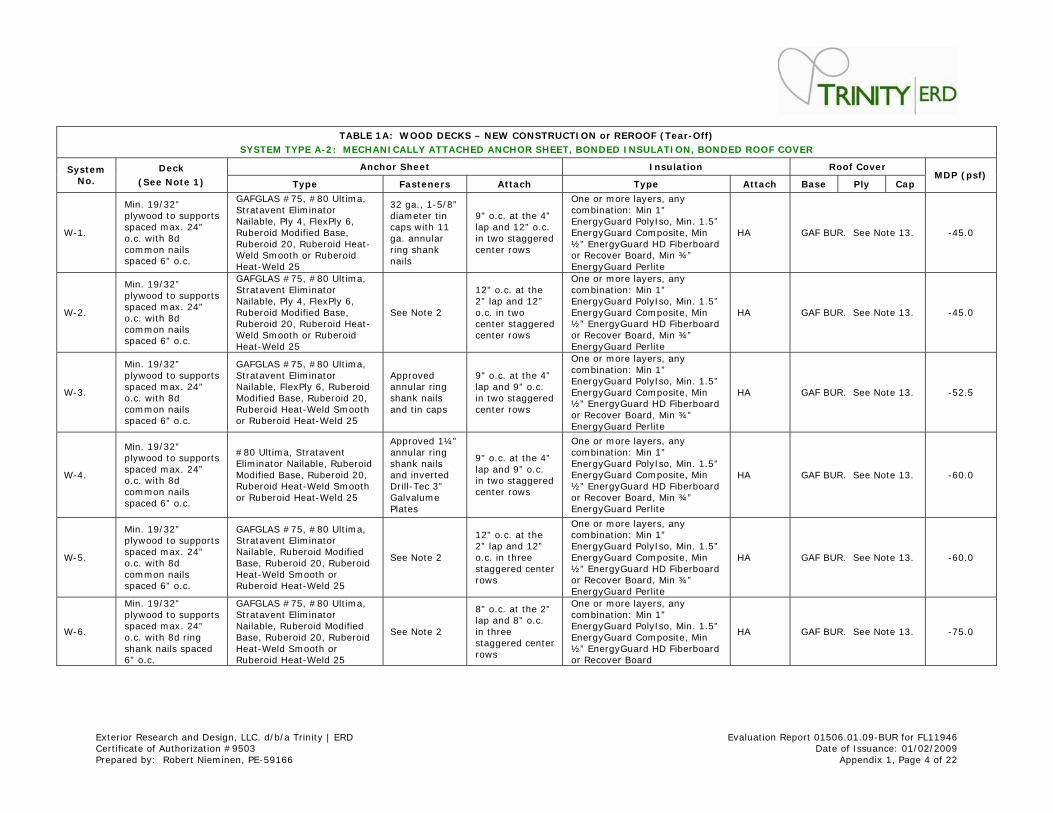
TABLE 1 A: W OOD DECKS – NEW CONSTRUCTI ON or REROOF ( Tear- Off)
SYSTEM TYPE A- 2 : MECHANI CALLY ATTACHED ANCHOR SHEET, BONDED I NSULATI ON, BONDED ROOF COVER
Anchor Sheet I nsulat ion Roof Cover System No.
Deck
( See Note 1 ) Type Fasteners At tach Type At tach Base Ply Cap MDP ( psf)
W-1.
Min. 19/ 32” plywood to supports spaced m ax. 24” o.c. with 8d com mon nails spaced 6” o.c.
GAFGLAS # 75, # 80 Ult im a, St ratavent Elim inator Nailable, Ply 4, FlexPly 6, Ruberoid Modified Base, Ruberoid 20, Ruberoid Heat -Weld Sm ooth or Ruberoid Heat -Weld 25
32 ga., 1-5/ 8” diam eter t in caps with 11 ga. annular r ing shank nails
9" o.c. at the 4” lap and 12” o.c. in two staggered center rows
One or m ore layers, any com binat ion: Min 1” EnergyGuard PolyI so, Min. 1.5” EnergyGuard Com posite, Min ½” EnergyGuard HD Fiberboard or Recover Board, Min ¾” EnergyGuard Perlite
HA GAF BUR. See Note 13. -45.0
W-2.
Min. 19/ 32” plywood to supports spaced m ax. 24” o.c. with 8d com mon nails spaced 6” o.c.
GAFGLAS # 75, # 80 Ult im a, St ratavent Elim inator Nailable, Ply 4, FlexPly 6, Ruberoid Modified Base, Ruberoid 20, Ruberoid Heat -Weld Sm ooth or Ruberoid Heat -Weld 25
See Note 2
12" o.c. at the 2” lap and 12” o.c. in two center staggered center rows
One or m ore layers, any com binat ion: Min 1” EnergyGuard PolyI so, Min. 1.5” EnergyGuard Com posite, Min ½” EnergyGuard HD Fiberboard or Recover Board, Min ¾” EnergyGuard Perlite
HA GAF BUR. See Note 13. -45.0
W-3.
Min. 19/ 32” plywood to supports spaced m ax. 24” o.c. with 8d com mon nails spaced 6” o.c.
GAFGLAS # 75, # 80 Ult im a, St ratavent Elim inator Nailable, FlexPly 6, Ruberoid Modified Base, Ruberoid 20, Ruberoid Heat -Weld Sm ooth or Ruberoid Heat-Weld 25
Approved annular r ing shank nails and t in caps
9" o.c. at the 4” lap and 9” o.c. in two staggered center rows
One or m ore layers, any com binat ion: Min 1” EnergyGuard PolyI so, Min. 1.5” EnergyGuard Com posite, Min ½” EnergyGuard HD Fiberboard or Recover Board, Min ¾” EnergyGuard Perlite
HA GAF BUR. See Note 13. -52.5
W-4.
Min. 19/ 32” plywood to supports spaced m ax. 24” o.c. with 8d com mon nails spaced 6” o.c.
# 80 Ult ima, St ratavent Elim inator Nailable, Ruberoid Modified Base, Ruberoid 20, Ruberoid Heat -Weld Sm ooth or Ruberoid Heat-Weld 25
Approved 1¼” annular r ing shank nails and inverted Drill-Tec 3” Galvalume Plates
9" o.c. at the 4” lap and 9” o.c. in two staggered center rows
One or m ore layers, any com binat ion: Min 1” EnergyGuard PolyI so, Min. 1.5” EnergyGuard Com posite, Min ½” EnergyGuard HD Fiberboard or Recover Board, Min ¾” EnergyGuard Perlite
HA GAF BUR. See Note 13. -60.0
W-5.
Min. 19/ 32” plywood to supports spaced m ax. 24” o.c. with 8d com mon nails spaced 6” o.c.
GAFGLAS # 75, # 80 Ult im a, St ratavent Elim inator Nailable, Ruberoid Modified Base, Ruberoid 20, Ruberoid Heat -Weld Sm ooth or Ruberoid Heat -Weld 25
See Note 2
12" o.c. at the 2” lap and 12” o.c. in three staggered center rows
One or m ore layers, any com binat ion: Min 1” EnergyGuard PolyI so, Min. 1.5” EnergyGuard Com posite, Min ½” EnergyGuard HD Fiberboard or Recover Board, Min ¾” EnergyGuard Perlite
HA GAF BUR. See Note 13. -60.0
W-6.
Min. 19/ 32” plywood to supports spaced m ax. 24” o.c. with 8d ring shank nails spaced 6” o.c.
GAFGLAS # 75, # 80 Ult im a, St ratavent Elim inator Nailable, Ruberoid Modified Base, Ruberoid 20, Ruberoid Heat -Weld Sm ooth or Ruberoid Heat -Weld 25
See Note 2
8" o.c. at the 2” lap and 8” o.c. in three staggered center rows
One or m ore layers, any com binat ion: Min 1” EnergyGuard PolyI so, Min. 1.5” EnergyGuard Com posite, Min ½” EnergyGuard HD Fiberboard or Recover Board
HA GAF BUR. See Note 13. -75.0
Exterior Research and Design, LLC. d/ b/ a Trinity | ERD Evaluat ion Report 01506.01.09-BUR for FL11946 Cert ificate of Authorizat ion # 9503 Date of I ssuance: 01/ 02/ 2009 Prepared by: Robert Niem inen, PE-59166 Appendix 1, Page 5 of 22
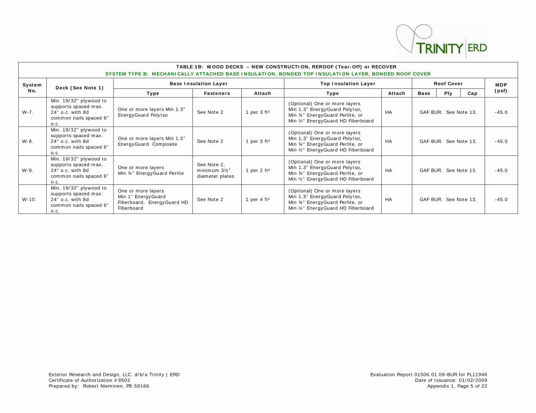
TABLE 1 B: W OOD DECKS – NEW CONSTRUCTI ON, REROOF ( Tear- Off) or RECOVER
SYSTEM TYPE B: MECHANI CALLY ATTACHED BASE I NSULATI ON, BONDED TOP I NSULATI ON LAYER, BONDED ROOF COVER
Base I nsulat ion Layer Top I nsulat ion Layer Roof Cover System No.
Deck ( See Note 1 ) Type Fasteners At tach Type At tach Base Ply Cap
MDP ( psf)
W-7.
Min. 19/ 32” plywood to supports spaced m ax. 24” o.c. with 8d com mon nails spaced 6” o.c.
One or m ore layers Min 1.3” EnergyGuard PolyI so
See Note 2 1 per 3 ft ²
(Opt ional) One or m ore layers Min 1.3” EnergyGuard PolyI so, Min ¾” EnergyGuard Perlite, or Min ½” EnergyGuard HD Fiberboard
HA GAF BUR. See Note 13. -45.0
W-8.
Min. 19/ 32” plywood to supports spaced m ax. 24” o.c. with 8d com mon nails spaced 6” o.c.
One or m ore layers Min 1.5” EnergyGuard Com posite
See Note 2 1 per 3 ft ²
(Opt ional) One or m ore layers Min 1.3” EnergyGuard PolyI so, Min ¾” EnergyGuard Perlite, or Min ½” EnergyGuard HD Fiberboard
HA GAF BUR. See Note 13. -45.0
W-9.
Min. 19/ 32” plywood to supports spaced m ax. 24” o.c. with 8d com mon nails spaced 6” o.c.
One or m ore layers Min ¾” EnergyGuard Perlite
See Note 2, m inim um 3½” diam eter plates
1 per 2 ft ²
(Opt ional) One or m ore layers Min 1.3” EnergyGuard PolyI so, Min ¾” EnergyGuard Perlite, or Min ½” EnergyGuard HD Fiberboard
HA GAF BUR. See Note 13. -45.0
W-10.
Min. 19/ 32” plywood to supports spaced m ax. 24” o.c. with 8d com mon nails spaced 6” o.c.
One or m ore layers Min 1” EnergyGuard Fiberboard, EnergyGuard HD Fiberboard
See Note 2 1 per 4 ft ²
(Opt ional) One or m ore layers Min 1.3” EnergyGuard PolyI so, Min ¾” EnergyGuard Perlite, or Min ½” EnergyGuard HD Fiberboard
HA GAF BUR. See Note 13. -45.0
Exterior Research and Design, LLC. d/ b/ a Trinity | ERD Evaluat ion Report 01506.01.09-BUR for FL11946 Cert ificate of Authorizat ion # 9503 Date of I ssuance: 01/ 02/ 2009 Prepared by: Robert Niem inen, PE-59166 Appendix 1, Page 6 of 22
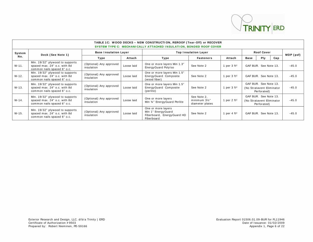
TABLE 1 C: W OOD DECKS – NEW CONSTRUCTI ON, REROOF ( T ear- Off) or RECOVER
SYSTEM TYPE C: MECHANI CALLY ATTACHED I NSULATI ON, B ONDED ROOF COVER
Base I nsulat ion Layer Top I nsulat ion Layer Roof Cover System No.
Deck ( See Note 1 ) Type At tach Type Fasteners At tach Base Ply Cap
MDP ( psf)
W-11. Min. 19/ 32” plywood to supports spaced m ax. 24” o.c. with 8d com mon nails spaced 6” o.c.
(Opt ional) Any approved insulat ion
Loose laid One or m ore layers Min 1.3” EnergyGuard PolyI so
See Note 2 1 per 3 ft ² GAF BUR. See Note 13. -45.0
W-12. Min. 19/ 32” plywood to supports spaced m ax. 24” o.c. with 8d com mon nails spaced 6” o.c.
(Opt ional) Any approved insulat ion
Loose laid One or m ore layers Min 1.5” EnergyGuard Com posite (wood fiber)
See Note 2 1 per 3 ft ² GAF BUR. See Note 13. -45.0
W-13. Min. 19/ 32” plywood to supports spaced m ax. 24” o.c. with 8d com mon nails spaced 6” o.c.
(Opt ional) Any approved insulat ion
Loose laid One or m ore layers Min 1.5” EnergyGuard Com posite (perlite)
See Note 2 1 per 3 ft ² GAF BUR. See Note 13.
(No St ratavent Elim inator Perforated)
-45.0
W-14. Min. 19/ 32” plywood to supports spaced m ax. 24” o.c. with 8d com mon nails spaced 6” o.c.
(Opt ional) Any approved insulat ion
Loose laid One or m ore layers Min ¾” EnergyGuard Perlite
See Note 2, m inim um 3½” diam eter plates
1 per 2 ft ² GAF BUR. See Note 13.
(No St ratavent Elim inator Perforated)
-45.0
W-15. Min. 19/ 32” plywood to supports spaced m ax. 24” o.c. with 8d com mon nails spaced 6” o.c.
(Opt ional) Any approved insulat ion
Loose laid
One or m ore layers Min 1” EnergyGuard Fiberboard, EnergyGuard HD Fiberboard
See Note 2 1 per 4 ft ² GAF BUR. See Note 13. -45.0
Exterior Research and Design, LLC. d/ b/ a Trinity | ERD Evaluat ion Report 01506.01.09-BUR for FL11946 Cert ificate of Authorizat ion # 9503 Date of I ssuance: 01/ 02/ 2009 Prepared by: Robert Niem inen, PE-59166 Appendix 1, Page 7 of 22
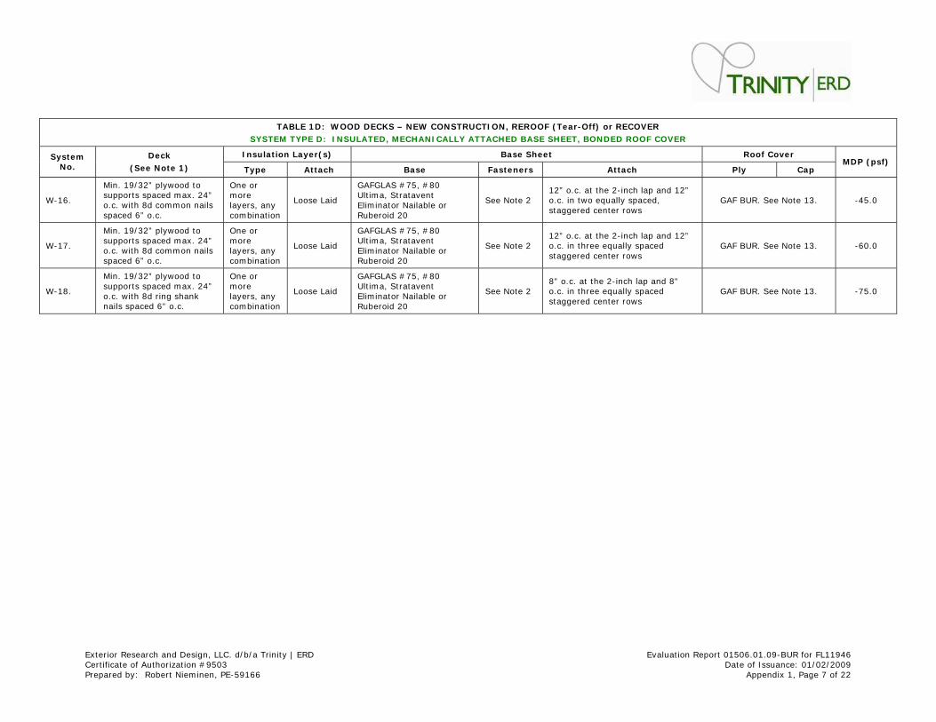
TABLE 1 D: W OOD DECKS – NEW CONSTRUCTI ON, REROOF ( T ear- Off) or RECOVER
SYSTEM TYPE D: I NSULATED, MECHANI CALLY ATTACHED BASE SHEET, BONDED ROOF COVER
I nsulat ion Layer( s) Base Sheet Roof Cover System No.
Deck
( See Note 1 ) Type At tach Base Fasteners At tach Ply Cap MDP ( psf)
W-16.
Min. 19/ 32” plywood to supports spaced m ax. 24” o.c. with 8d comm on nails spaced 6” o.c.
One or m ore layers, any com binat ion
Loose Laid
GAFGLAS # 75, # 80 Ult im a, St ratavent Elim inator Nailable or Ruberoid 20
See Note 2 12” o.c. at the 2- inch lap and 12” o.c. in two equally spaced, staggered center rows
GAF BUR. See Note 13. -45.0
W-17.
Min. 19/ 32” plywood to supports spaced m ax. 24” o.c. with 8d comm on nails spaced 6” o.c.
One or m ore layers, any com binat ion
Loose Laid
GAFGLAS # 75, # 80 Ult im a, St ratavent Elim inator Nailable or Ruberoid 20
See Note 2 12” o.c. at the 2- inch lap and 12” o.c. in three equally spaced staggered center rows
GAF BUR. See Note 13. -60.0
W-18.
Min. 19/ 32” plywood to supports spaced m ax. 24” o.c. with 8d ring shank nails spaced 6” o.c.
One or m ore layers, any com binat ion
Loose Laid
GAFGLAS # 75, # 80 Ult im a, St ratavent Elim inator Nailable or Ruberoid 20
See Note 2 8” o.c. at the 2- inch lap and 8” o.c. in three equally spaced staggered center rows
GAF BUR. See Note 13. -75.0

Exterior Research and Design, LLC. d/ b/ a Trinity | ERD Evaluat ion Report 01506.01.09-BUR for FL11946 Cert ificate of Authorizat ion # 9503 Date of I ssuance: 01/ 02/ 2009 Prepared by: Robert Niem inen, PE-59166 Appendix 1, Page 8 of 22
TABLE 1 E: W OOD DECKS – NEW CONSTRUCTI ON or REROOF ( Tear- Off)
SYSTEM TYPE E: NON- I NSULATED, MECHANI CALLY ATTACHED BASE SHEET, BONDED ROOF COVER
Base Sheet Roof Cover System
No. Deck ( See Note 1 )
Type Fasteners
( see note 2 ) At tach Ply Cap
MDP ( psf)
W-19.
Min. 19/ 32” plywood to supports spaced m ax. 24” o.c. with 8d comm on nails spaced 6” o.c.
GAFGLAS # 75, # 80 Ult im a, St ratavent Elim inator Nailable, Ply 4, FlexPly 6, Ruberoid Modified Base, Ruberoid 20, Ruberoid Heat -Weld Sm ooth or Ruberoid Heat -Weld 25
32 ga., 1-5/ 8” diameter t in caps with 11 ga. annular r ing shank nails
9" o.c. at the 4” lap and 12” o.c. in two staggered center rows
GAF BUR. See Note 13. -45.0
W-20.
Min. 19/ 32” plywood to supports spaced m ax. 24” o.c. with 8d comm on nails spaced 6” o.c.
GAFGLAS # 75, # 80 Ult im a, St ratavent Elim inator Nailable, Ply 4, FlexPly 6, Ruberoid Modified Base, Ruberoid 20, Ruberoid Heat -Weld Sm ooth or Ruberoid Heat -Weld 25
See Note 2 12" o.c. at the 2” lap and 12” o.c. in two center staggered center rows
GAF BUR. See Note 13. -45.0
W-21.
Min. 19/ 32” plywood to supports spaced m ax. 24” o.c. with 8d comm on nails spaced 6” o.c.
GAFGLAS # 75, # 80 Ult im a, St ratavent Elim inator Nailable, FlexPly 6, Ruberoid Modified Base, Ruberoid 20, Ruberoid Heat -Weld Sm ooth or Ruberoid Heat -Weld 25
Approved annular r ing shank nails and t in caps
9" o.c. at the 4” lap and 9” o.c. in two staggered center rows
GAF BUR. See Note 13. -52.5
W-22.
Min. 19/ 32” plywood to supports spaced m ax. 24” o.c. with 8d comm on nails spaced 6” o.c.
# 80 Ult im a, St ratavent Elim inator Nailable, Ruberoid Modified Base, Ruberoid 20, Ruberoid Heat -Weld Smooth or Ruberoid Heat -Weld 25
Approved 1¼” annular r ing shank nails and inverted Drill-Tec 3” Galvalum e Plates
9" o.c. at the 4” lap and 9” o.c. in two staggered center rows
GAF BUR. See Note 13. -60.0
W-23.
Min. 19/ 32” plywood to supports spaced m ax. 24” o.c. with 8d comm on nails spaced 6” o.c.
GAFGLAS # 75, # 80 Ult im a, St ratavent Elim inator Nailable, Ruberoid Modified Base, Ruberoid 20, Ruberoid Heat -Weld Sm ooth or Ruberoid Heat -Weld 25
See Note 2 12" o.c. at the 2” lap and 12” o.c. in three staggered center rows
GAF BUR. See Note 13. -60.0
W-24.
Min. 19/ 32” plywood to supports spaced m ax. 24” o.c. with 8d ring shank nails spaced 6” o.c.
GAFGLAS # 75, # 80 Ult im a, St ratavent Elim inator Nailable, Ruberoid Modified Base, Ruberoid 20, Ruberoid Heat -Weld Sm ooth or Ruberoid Heat -Weld 25
See Note 2 8" o.c. at the 2” lap and 8” o.c. in three staggered center rows
GAF BUR. See Note 13. -75.0
Exterior Research and Design, LLC. d/ b/ a Trinity | ERD Evaluat ion Report 01506.01.09-BUR for FL11946 Cert ificate of Authorizat ion # 9503 Date of I ssuance: 01/ 02/ 2009 Prepared by: Robert Niem inen, PE-59166 Appendix 1, Page 9 of 22
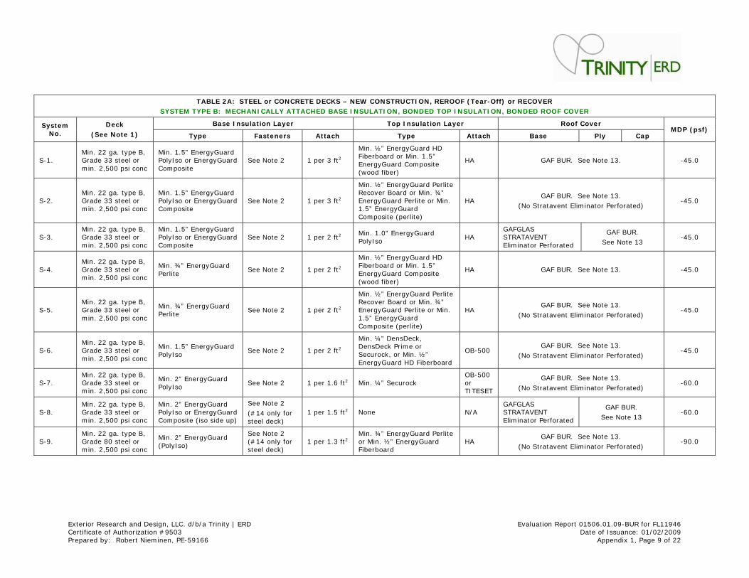
TABLE 2 A: STEEL or CONCRETE DECKS – NEW CONSTRUCTI ON, REROOF ( Tear- Off) or RECOVER
SYSTEM TYPE B: MECHANI CALLY ATTACHED BASE I NSU LATI ON, BONDED TOP I NSULATI ON, BONDED ROOF COVER
Base I nsulat ion Layer Top I nsulat ion Layer Roof Cov er System No.
Deck
( See Note 1 ) Type Fasteners At tach Type At tach Base Ply Cap MDP ( psf)
S-1. Min. 22 ga. type B, Grade 33 steel or m in. 2,500 psi conc
Min. 1.5” EnergyGuard PolyI so or EnergyGuard Composite
See Note 2 1 per 3 ft 2
Min. ½” EnergyGuard HD Fiberboard or Min. 1.5” EnergyGuard Com posite (wood fiber)
HA GAF BUR. See Note 13. -45.0
S-2. Min. 22 ga. type B, Grade 33 steel or m in. 2,500 psi conc
Min. 1.5” EnergyGuard PolyI so or EnergyGuard Composite
See Note 2 1 per 3 ft 2
Min. ½” EnergyGuard Perlite Recover Board or Min. ¾” EnergyGuard Perlite or Min. 1.5” EnergyGuard Composite (perlite)
HA GAF BUR. See Note 13.
(No St ratavent Elim inator Perforated) -45.0
S-3. Min. 22 ga. type B, Grade 33 steel or m in. 2,500 psi conc
Min. 1.5” EnergyGuard PolyI so or EnergyGuard Composite
See Note 2 1 per 2 ft 2 Min. 1.0” EnergyGuard PolyI so
HA GAFGLAS STRATAVENT Elim inator Perforated
GAF BUR.
See Note 13 -45.0
S-4. Min. 22 ga. type B, Grade 33 steel or m in. 2,500 psi conc
Min. ¾” EnergyGuard Perlite
See Note 2 1 per 2 ft 2
Min. ½” EnergyGuard HD Fiberboard or Min. 1.5” EnergyGuard Com posite (wood fiber)
HA GAF BUR. See Note 13. -45.0
S-5. Min. 22 ga. type B, Grade 33 steel or m in. 2,500 psi conc
Min. ¾” EnergyGuard Perlite
See Note 2 1 per 2 ft 2
Min. ½” EnergyGuard Perlite Recover Board or Min. ¾” EnergyGuard Perlite or Min. 1.5” EnergyGuard Composite (perlite)
HA GAF BUR. See Note 13.
(No St ratavent Elim inator Perforated) -45.0
S-6. Min. 22 ga. type B, Grade 33 steel or m in. 2,500 psi conc
Min. 1.5” EnergyGuard PolyI so
See Note 2 1 per 2 ft 2
Min. ¼” DensDeck, DensDeck Prime or Securock, or Min. ½” EnergyGuard HD Fiberboard
OB-500 GAF BUR. See Note 13.
(No St ratavent Elim inator Perforated) -45.0
S-7. Min. 22 ga. type B, Grade 33 steel or m in. 2,500 psi conc
Min. 2” EnergyGuard PolyI so
See Note 2 1 per 1.6 ft 2 Min. ¼” Securock OB-500 or TI TESET
GAF BUR. See Note 13.
(No St ratavent Elim inator Perforated) -60.0
S-8. Min. 22 ga. type B, Grade 33 steel or m in. 2,500 psi conc
Min. 2” EnergyGuard PolyI so or EnergyGuard Composite ( iso side up)
See Note 2
(# 14 only for steel deck)
1 per 1.5 ft 2 None N/ A GAFGLAS STRATAVENT Elim inator Perforated
GAF BUR.
See Note 13 -60.0
S-9. Min. 22 ga. type B, Grade 80 steel or m in. 2,500 psi conc
Min. 2” EnergyGuard (PolyI so)
See Note 2 (# 14 only for steel deck)
1 per 1.3 ft 2 Min. ¾” EnergyGuard Perlite or Min. ½” EnergyGuard Fiberboard
HA GAF BUR. See Note 13.
(No St ratavent Elim inator Perforated) -90.0
Exterior Research and Design, LLC. d/ b/ a Trinity | ERD Evaluat ion Report 01506.01.09-BUR for FL11946 Cert ificate of Authorizat ion # 9503 Date of I ssuance: 01/ 02/ 2009 Prepared by: Robert Niem inen, PE-59166 Appendix 1, Page 10 of 22
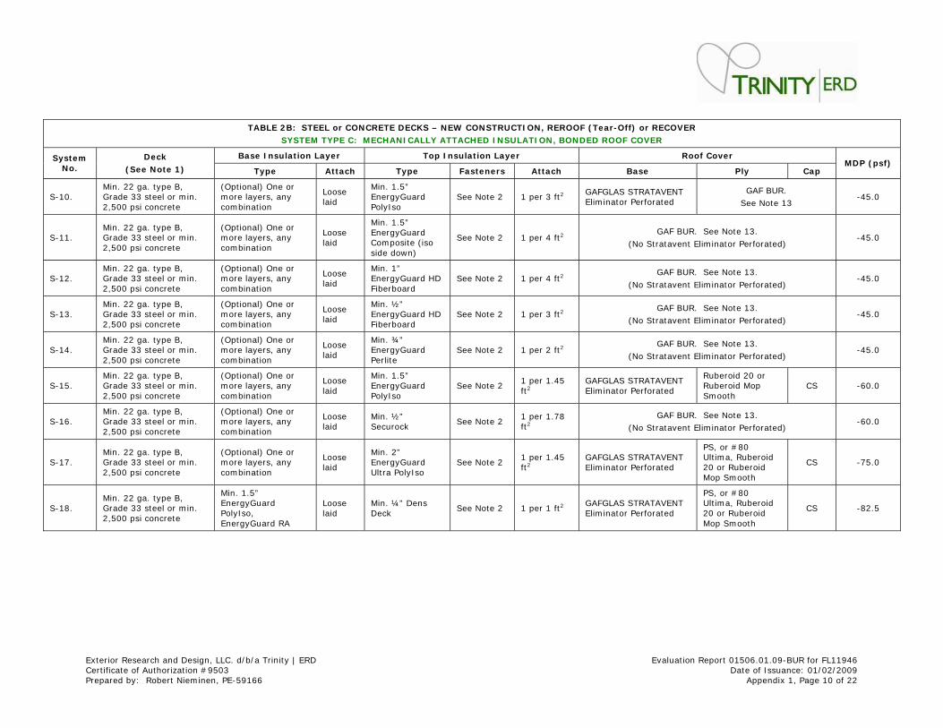
TABLE 2 B: STEEL or CONCRETE DECKS – NEW CONSTRUCTI ON, REROOF ( Tear- Off) or RECOVER
SYSTEM TYPE C: MECHANI CALLY ATTACHED I NSULATI ON, B ONDED ROOF COVER
Base I nsulat ion Layer Top I nsulat ion Layer Roof Cover System No.
Deck
( See Note 1 ) Type At tach Type Fasteners At tach Base Ply Cap MDP ( psf)
S-10. Min. 22 ga. type B, Grade 33 steel or m in. 2,500 psi concrete
(Opt ional) One or m ore layers, any com binat ion
Loose laid
Min. 1.5” EnergyGuard PolyI so
See Note 2 1 per 3 ft 2 GAFGLAS STRATAVENT Elim inator Perforated
GAF BUR.
See Note 13 -45.0
S-11. Min. 22 ga. type B, Grade 33 steel or m in. 2,500 psi concrete
(Opt ional) One or m ore layers, any com binat ion
Loose laid
Min. 1.5” EnergyGuard Composite ( iso side down)
See Note 2 1 per 4 ft 2 GAF BUR. See Note 13.
(No St ratavent Elim inator Perforated) -45.0
S-12. Min. 22 ga. type B, Grade 33 steel or m in. 2,500 psi concrete
(Opt ional) One or m ore layers, any com binat ion
Loose laid
Min. 1” EnergyGuard HD Fiberboard
See Note 2 1 per 4 ft 2 GAF BUR. See Note 13.
(No St ratavent Elim inator Perforated) -45.0
S-13. Min. 22 ga. type B, Grade 33 steel or m in. 2,500 psi concrete
(Opt ional) One or m ore layers, any com binat ion
Loose laid
Min. ½” EnergyGuard HD Fiberboard
See Note 2 1 per 3 ft 2 GAF BUR. See Note 13.
(No St ratavent Elim inator Perforated) -45.0
S-14. Min. 22 ga. type B, Grade 33 steel or m in. 2,500 psi concrete
(Opt ional) One or m ore layers, any com binat ion
Loose laid
Min. ¾” EnergyGuard Perlite
See Note 2 1 per 2 ft 2 GAF BUR. See Note 13.
(No St ratavent Elim inator Perforated) -45.0
S-15. Min. 22 ga. type B, Grade 33 steel or m in. 2,500 psi concrete
(Opt ional) One or m ore layers, any com binat ion
Loose laid
Min. 1.5” EnergyGuard PolyI so
See Note 2 1 per 1.45 ft 2
GAFGLAS STRATAVENT Elim inator Perforated
Ruberoid 20 or Ruberoid Mop Sm ooth
CS -60.0
S-16. Min. 22 ga. type B, Grade 33 steel or m in. 2,500 psi concrete
(Opt ional) One or m ore layers, any com binat ion
Loose laid
Min. ½” Securock
See Note 2 1 per 1.78 ft 2
GAF BUR. See Note 13.
(No St ratavent Elim inator Perforated) -60.0
S-17. Min. 22 ga. type B, Grade 33 steel or m in. 2,500 psi concrete
(Opt ional) One or m ore layers, any com binat ion
Loose laid
Min. 2” EnergyGuard Ult ra PolyI so
See Note 2 1 per 1.45 ft 2
GAFGLAS STRATAVENT Elim inator Perforated
PS, or # 80 Ult im a, Ruberoid 20 or Ruberoid Mop Sm ooth
CS -75.0
S-18. Min. 22 ga. type B, Grade 33 steel or m in. 2,500 psi concrete
Min. 1.5” EnergyGuard PolyI so, EnergyGuard RA
Loose laid
Min. ¼” Dens Deck
See Note 2 1 per 1 ft 2 GAFGLAS STRATAVENT Elim inator Perforated
PS, or # 80 Ult im a, Ruberoid 20 or Ruberoid Mop Sm ooth
CS -82.5
Exterior Research and Design, LLC. d/ b/ a Trinity | ERD Evaluat ion Report 01506.01.09-BUR for FL11946 Cert ificate of Authorizat ion # 9503 Date of I ssuance: 01/ 02/ 2009 Prepared by: Robert Niem inen, PE-59166 Appendix 1, Page 11 of 22
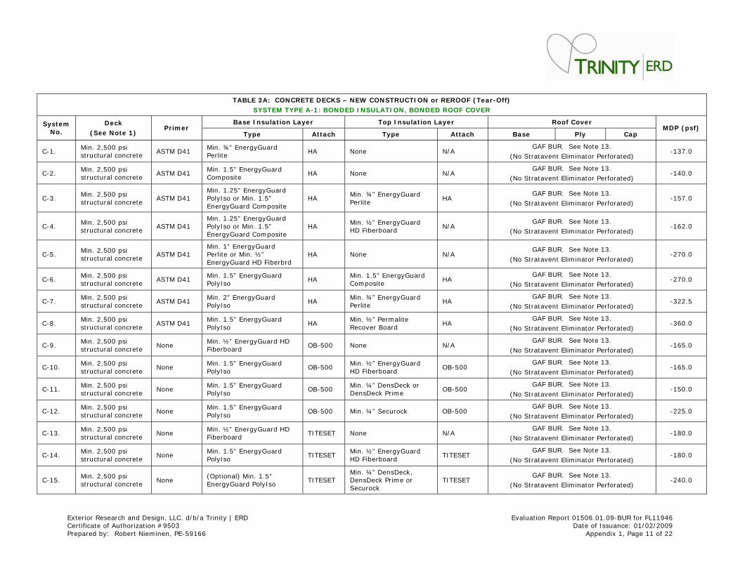
TABLE 3 A: CONCRETE DECKS – NEW CONSTRUCTI ON or RER OOF ( Tear- Off)
SYSTEM TYPE A- 1 : BONDED I NSULATI ON, BONDED ROOF COV ER
Base I nsulat ion Layer Top I nsulat ion Layer Roof Cov er System No.
Deck
( See Note 1 ) Pr im er
Type At tach Type At tach Base Ply Cap MDP ( psf)
C-1. Min. 2,500 psi st ructural concrete
ASTM D41 Min. ¾” EnergyGuard Perlite
HA None N/ A GAF BUR. See Note 13.
(No St ratavent Elim inator Perforated) -137.0
C-2. Min. 2,500 psi st ructural concrete
ASTM D41 Min. 1.5” EnergyGuard Composite
HA None N/ A GAF BUR. See Note 13.
(No St ratavent Elim inator Perforated) -140.0
C-3. Min. 2,500 psi st ructural concrete
ASTM D41 Min. 1.25” EnergyGuard PolyI so or Min. 1.5” EnergyGuard Com posite
HA Min. ¾” EnergyGuard Perlite
HA GAF BUR. See Note 13.
(No St ratavent Elim inator Perforated) -157.0
C-4. Min. 2,500 psi st ructural concrete
ASTM D41 Min. 1.25” EnergyGuard PolyI so or Min. 1.5” EnergyGuard Com posite
HA Min. ½” EnergyGuard HD Fiberboard
N/ A GAF BUR. See Note 13.
(No St ratavent Elim inator Perforated) -162.0
C-5. Min. 2,500 psi st ructural concrete
ASTM D41 Min. 1” EnergyGuard Perlite or Min. ½” EnergyGuard HD Fiberbrd
HA None N/ A GAF BUR. See Note 13.
(No St ratavent Elim inator Perforated) -270.0
C-6. Min. 2,500 psi st ructural concrete
ASTM D41 Min. 1.5” EnergyGuard PolyI so
HA Min. 1.5” EnergyGuard Composite
HA GAF BUR. See Note 13.
(No St ratavent Elim inator Perforated) -270.0
C-7. Min. 2,500 psi st ructural concrete
ASTM D41 Min. 2” EnergyGuard PolyI so
HA Min. ¾” EnergyGuard Perlite
HA GAF BUR. See Note 13.
(No St ratavent Elim inator Perforated) -322.5
C-8. Min. 2,500 psi st ructural concrete
ASTM D41 Min. 1.5” EnergyGuard PolyI so
HA Min. ½” Perm alite Recover Board
HA GAF BUR. See Note 13.
(No St ratavent Elim inator Perforated) -360.0
C-9. Min. 2,500 psi st ructural concrete
None Min. ½” EnergyGuard HD Fiberboard
OB-500 None N/ A GAF BUR. See Note 13.
(No St ratavent Elim inator Perforated) -165.0
C-10. Min. 2,500 psi st ructural concrete
None Min. 1.5” EnergyGuard PolyI so
OB-500 Min. ½” EnergyGuard HD Fiberboard
OB-500 GAF BUR. See Note 13.
(No St ratavent Elim inator Perforated) -165.0
C-11. Min. 2,500 psi st ructural concrete
None Min. 1.5” EnergyGuard PolyI so
OB-500 Min. ¼” DensDeck or DensDeck Prime
OB-500 GAF BUR. See Note 13.
(No St ratavent Elim inator Perforated) -150.0
C-12. Min. 2,500 psi st ructural concrete
None Min. 1.5” EnergyGuard PolyI so
OB-500 Min. ¼” Securock OB-500 GAF BUR. See Note 13.
(No St ratavent Elim inator Perforated) -225.0
C-13. Min. 2,500 psi st ructural concrete
None Min. ½” EnergyGuard HD Fiberboard
TI TESET None N/ A GAF BUR. See Note 13.
(No St ratavent Elim inator Perforated) -180.0
C-14. Min. 2,500 psi st ructural concrete
None Min. 1.5” EnergyGuard PolyI so
TI TESET Min. ½” EnergyGuard HD Fiberboard
TI TESET GAF BUR. See Note 13.
(No St ratavent Elim inator Perforated) -180.0
C-15. Min. 2,500 psi st ructural concrete
None (Opt ional) Min. 1.5” EnergyGuard PolyI so
TI TESET Min. ¼” DensDeck, DensDeck Prime or Securock
TI TESET GAF BUR. See Note 13.
(No St ratavent Elim inator Perforated) -240.0
Exterior Research and Design, LLC. d/ b/ a Trinity | ERD Evaluat ion Report 01506.01.09-BUR for FL11946 Cert ificate of Authorizat ion # 9503 Date of I ssuance: 01/ 02/ 2009 Prepared by: Robert Niem inen, PE-59166 Appendix 1, Page 12 of 22
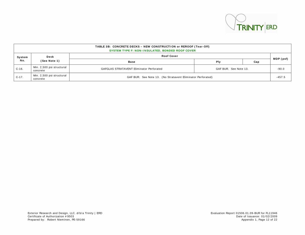
TABLE 3 B: CONCRETE DECKS – NEW CONSTRUCTI ON or RER OOF ( Tear- Off)
SYSTEM TYPE F: NON- I NSULATED, BONDED ROOF COVER
Roof Cover System No.
Deck
( See Note 1 ) Base Ply Cap MDP ( psf)
C-16. Min. 2,500 psi st ructural concrete
GAFGLAS STRATAVENT Elim inator Perforated GAF BUR. See Note 13. -90.0
C-17. Min. 2,500 psi st ructural concrete
GAF BUR. See Note 13. (No St ratavent Elim inator Perforated) -457.5
Exterior Research and Design, LLC. d/ b/ a Trinity | ERD Evaluat ion Report 01506.01.09-BUR for FL11946 Cert ificate of Authorizat ion # 9503 Date of I ssuance: 01/ 02/ 2009 Prepared by: Robert Niem inen, PE-59166 Appendix 1, Page 13 of 22
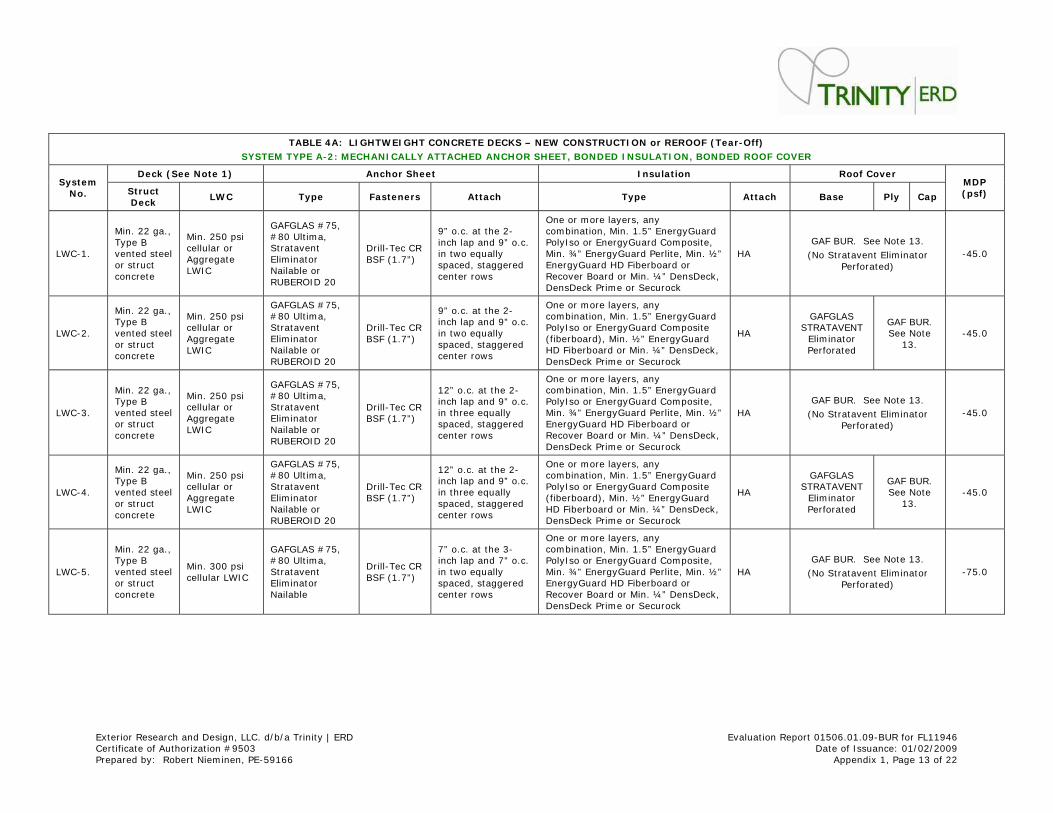
TABLE 4 A: LI GHTW EI GHT CONCRETE DECKS – NEW CONSTRU CTI ON or REROOF ( Tear- Off)
SYSTEM TYPE A- 2 : MECHANI CALLY ATTACHED ANCHOR SHEET, BONDED I NSULATI ON, BONDED ROOF COVER
Deck ( See Note 1 ) Anchor Sheet I nsulat ion Roof Cover System
No. St ruct Deck
LW C Type Fasteners At tach Type At tach Base Ply Cap
MDP ( psf)
LWC-1.
Min. 22 ga., Type B vented steel or st ruct concrete
Min. 250 psi cellular or Aggregate LWI C
GAFGLAS # 75, # 80 Ult ima, St ratavent Elim inator Nailable or RUBEROI D 20
Drill-Tec CR BSF (1.7” )
9” o.c. at the 2-inch lap and 9” o.c. in two equally spaced, staggered center rows
One or m ore layers, any combinat ion, Min. 1.5” EnergyGuard PolyI so or EnergyGuard Composite, Min. ¾” EnergyGuard Perlite, Min. ½” EnergyGuard HD Fiberboard or Recover Board or Min. ¼” DensDeck, DensDeck Prime or Securock
HA GAF BUR. See Note 13.
(No St ratavent Elim inator Perforated)
-45.0
LWC-2.
Min. 22 ga., Type B vented steel or st ruct concrete
Min. 250 psi cellular or Aggregate LWI C
GAFGLAS # 75, # 80 Ult ima, St ratavent Elim inator Nailable or RUBEROI D 20
Drill-Tec CR BSF (1.7” )
9” o.c. at the 2-inch lap and 9” o.c. in two equally spaced, staggered center rows
One or m ore layers, any combinat ion, Min. 1.5” EnergyGuard PolyI so or EnergyGuard Composite ( fiberboard) , Min. ½” EnergyGuard HD Fiberboard or Min. ¼” DensDeck, DensDeck Prime or Securock
HA
GAFGLAS STRATAVENT
Elim inator Perforated
GAF BUR. See Note
13. -45.0
LWC-3.
Min. 22 ga., Type B vented steel or st ruct concrete
Min. 250 psi cellular or Aggregate LWI C
GAFGLAS # 75, # 80 Ult ima, St ratavent Elim inator Nailable or RUBEROI D 20
Drill-Tec CR BSF (1.7” )
12” o.c. at the 2-inch lap and 9” o.c. in three equally spaced, staggered center rows
One or m ore layers, any combinat ion, Min. 1.5” EnergyGuard PolyI so or EnergyGuard Composite, Min. ¾” EnergyGuard Perlite, Min. ½” EnergyGuard HD Fiberboard or Recover Board or Min. ¼” DensDeck, DensDeck Prime or Securock
HA GAF BUR. See Note 13.
(No St ratavent Elim inator Perforated)
-45.0
LWC-4.
Min. 22 ga., Type B vented steel or st ruct concrete
Min. 250 psi cellular or Aggregate LWI C
GAFGLAS # 75, # 80 Ult ima, St ratavent Elim inator Nailable or RUBEROI D 20
Drill-Tec CR BSF (1.7” )
12” o.c. at the 2-inch lap and 9” o.c. in three equally spaced, staggered center rows
One or m ore layers, any combinat ion, Min. 1.5” EnergyGuard PolyI so or EnergyGuard Composite ( fiberboard) , Min. ½” EnergyGuard HD Fiberboard or Min. ¼” DensDeck, DensDeck Prime or Securock
HA
GAFGLAS STRATAVENT
Elim inator Perforated
GAF BUR. See Note
13. -45.0
LWC-5.
Min. 22 ga., Type B vented steel or st ruct concrete
Min. 300 psi cellular LWI C
GAFGLAS # 75, # 80 Ult ima, St ratavent Elim inator Nailable
Drill-Tec CR BSF (1.7” )
7” o.c. at the 3-inch lap and 7” o.c. in two equally spaced, staggered center rows
One or m ore layers, any combinat ion, Min. 1.5” EnergyGuard PolyI so or EnergyGuard Composite, Min. ¾” EnergyGuard Perlite, Min. ½” EnergyGuard HD Fiberboard or Recover Board or Min. ¼” DensDeck, DensDeck Prime or Securock
HA GAF BUR. See Note 13.
(No St ratavent Elim inator Perforated)
-75.0
Exterior Research and Design, LLC. d/ b/ a Trinity | ERD Evaluat ion Report 01506.01.09-BUR for FL11946 Cert ificate of Authorizat ion # 9503 Date of I ssuance: 01/ 02/ 2009 Prepared by: Robert Niem inen, PE-59166 Appendix 1, Page 14 of 22
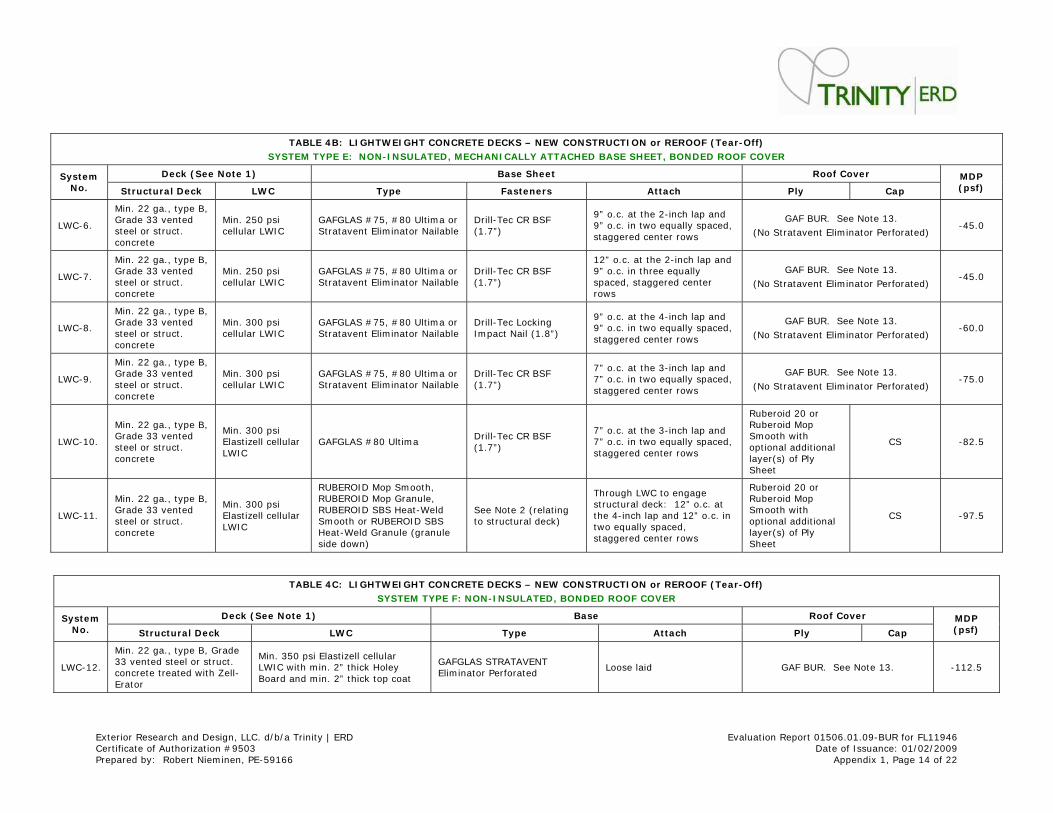
TABLE 4 B: LI GHTW EI GHT CONCRETE DECKS – NEW CONSTRU CTI ON or REROOF ( Tear- Off)
SYSTEM TYPE E: NON- I NSULATED, MECHANI CALLY ATTACHED BASE SHEET, BONDED ROOF COVER
Deck ( See Note 1 ) Base Sheet Roof Cover System No. St ructura l Deck LW C Type Fasteners At tach Ply Cap
MDP ( psf)
LWC-6.
Min. 22 ga., type B, Grade 33 vented steel or st ruct . concrete
Min. 250 psi cellular LWI C
GAFGLAS # 75, # 80 Ult im a or St ratavent Elim inator Nailable
Drill-Tec CR BSF (1.7” )
9” o.c. at the 2- inch lap and 9” o.c. in two equally spaced, staggered center rows
GAF BUR. See Note 13.
(No St ratavent Elim inator Perforated) -45.0
LWC-7.
Min. 22 ga., type B, Grade 33 vented steel or st ruct . concrete
Min. 250 psi cellular LWI C
GAFGLAS # 75, # 80 Ult im a or St ratavent Elim inator Nailable
Drill-Tec CR BSF (1.7” )
12” o.c. at the 2- inch lap and 9” o.c. in three equally spaced, staggered center rows
GAF BUR. See Note 13.
(No St ratavent Elim inator Perforated) -45.0
LWC-8.
Min. 22 ga., type B, Grade 33 vented steel or st ruct . concrete
Min. 300 psi cellular LWI C
GAFGLAS # 75, # 80 Ult im a or St ratavent Elim inator Nailable
Drill-Tec Locking I mpact Nail (1.8” )
9” o.c. at the 4- inch lap and 9” o.c. in two equally spaced, staggered center rows
GAF BUR. See Note 13.
(No St ratavent Elim inator Perforated) -60.0
LWC-9.
Min. 22 ga., type B, Grade 33 vented steel or st ruct . concrete
Min. 300 psi cellular LWI C
GAFGLAS # 75, # 80 Ult im a or St ratavent Elim inator Nailable
Drill-Tec CR BSF (1.7” )
7” o.c. at the 3- inch lap and 7” o.c. in two equally spaced, staggered center rows
GAF BUR. See Note 13.
(No St ratavent Elim inator Perforated) -75.0
LWC-10.
Min. 22 ga., type B, Grade 33 vented steel or st ruct . concrete
Min. 300 psi Elast izell cellular LWI C
GAFGLAS # 80 Ult im a Drill-Tec CR BSF (1.7” )
7” o.c. at the 3- inch lap and 7” o.c. in two equally spaced, staggered center rows
Ruberoid 20 or Ruberoid Mop Sm ooth with opt ional addit ional layer(s) of Ply Sheet
CS -82.5
LWC-11.
Min. 22 ga., type B, Grade 33 vented steel or st ruct . concrete
Min. 300 psi Elast izell cellular LWI C
RUBEROI D Mop Sm ooth, RUBEROI D Mop Granule, RUBEROI D SBS Heat -Weld Sm ooth or RUBEROI D SBS Heat -Weld Granule (granule side down)
See Note 2 ( relat ing to st ructural deck)
Through LWC to engage st ructural deck: 12” o.c. at the 4- inch lap and 12” o.c. in two equally spaced, staggered center rows
Ruberoid 20 or Ruberoid Mop Sm ooth with opt ional addit ional layer(s) of Ply Sheet
CS -97.5
TABLE 4 C: LI GHTW EI GHT CONCRETE DECKS – NEW CONSTRU CTI ON or REROOF ( Tear- Off)
SYSTEM TYPE F: NON- I NSULATED, BONDED ROOF COVER
Deck ( See Note 1 ) Base Roof Cover System No. St ructura l Deck LW C Type At tach Ply Cap
MDP ( psf)
LWC-12.
Min. 22 ga., type B, Grade 33 vented steel or st ruct . concrete t reated with Zell-Erator
Min. 350 psi Elast izell cellular LWI C with m in. 2” thick Holey Board and m in. 2” thick top coat
GAFGLAS STRATAVENT Elim inator Perforated
Loose laid GAF BUR. See Note 13. -112.5
Exterior Research and Design, LLC. d/ b/ a Trinity | ERD Evaluat ion Report 01506.01.09-BUR for FL11946 Cert ificate of Authorizat ion # 9503 Date of I ssuance: 01/ 02/ 2009 Prepared by: Robert Niem inen, PE-59166 Appendix 1, Page 15 of 22
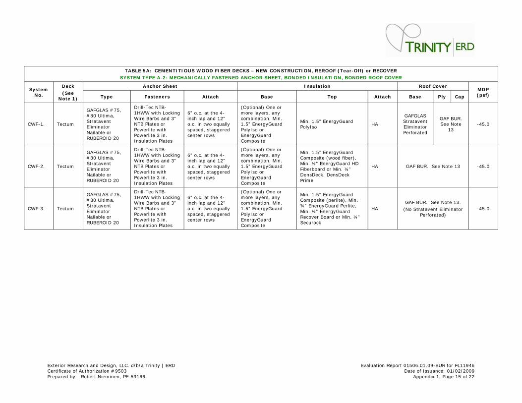
TABLE 5 A: CEMENTI TI OUS W OOD FI BER DECKS – NE W CONSTRUCTI ON, REROOF ( Tear- Off) or RECOVER
SYSTEM TYPE A- 2 : MECHANI CALLY FASTENED ANCHOR SHEET, BONDED I NSULATI ON, BONDED ROOF COVER
Anchor Sheet I nsulat ion Roof Cover System
No.
Deck
( See Note 1 ) Type Fasteners At tach Base Top At tach Base Ply Cap
MDP ( psf)
CWF-1. Tectum
GAFGLAS # 75, # 80 Ult ima, St ratavent Elim inator Nailable or RUBEROI D 20
Drill-Tec NTB-1HWW with Locking Wire Barbs and 3” NTB Plates or Powerlite with Powerlite 3 in. I nsulat ion Plates
6” o.c. at the 4-inch lap and 12” o.c. in two equally spaced, staggered center rows
(Opt ional) One or m ore layers, any com binat ion, Min. 1.5” EnergyGuard PolyI so or EnergyGuard Composite
Min. 1.5” EnergyGuard PolyI so
HA
GAFGLAS St ratavent Elim inator Perforated
GAF BUR. See Note
13 -45.0
CWF-2. Tectum
GAFGLAS # 75, # 80 Ult ima, St ratavent Elim inator Nailable or RUBEROI D 20
Drill-Tec NTB-1HWW with Locking Wire Barbs and 3” NTB Plates or Powerlite with Powerlite 3 in. I nsulat ion Plates
6” o.c. at the 4-inch lap and 12” o.c. in two equally spaced, staggered center rows
(Opt ional) One or m ore layers, any com binat ion, Min. 1.5” EnergyGuard PolyI so or EnergyGuard Composite
Min. 1.5” EnergyGuard Composite (wood fiber) , Min. ½” EnergyGuard HD Fiberboard or Min. ¼” DensDeck, DensDeck Prime
HA GAF BUR. See Note 13 -45.0
CWF-3. Tectum
GAFGLAS # 75, # 80 Ult ima, St ratavent Elim inator Nailable or RUBEROI D 20
Drill-Tec NTB-1HWW with Locking Wire Barbs and 3” NTB Plates or Powerlite with Powerlite 3 in. I nsulat ion Plates
6” o.c. at the 4-inch lap and 12” o.c. in two equally spaced, staggered center rows
(Opt ional) One or m ore layers, any com binat ion, Min. 1.5” EnergyGuard PolyI so or EnergyGuard Composite
Min. 1.5” EnergyGuard Composite (perlite) , Min. ¾” EnergyGuard Perlite, Min. ½” EnergyGuard Recover Board or Min. ¼” Securock
HA GAF BUR. See Note 13.
(No St ratavent Elim inator Perforated)
-45.0
Exterior Research and Design, LLC. d/ b/ a Trinity | ERD Evaluat ion Report 01506.01.09-BUR for FL11946 Cert ificate of Authorizat ion # 9503 Date of I ssuance: 01/ 02/ 2009 Prepared by: Robert Niem inen, PE-59166 Appendix 1, Page 16 of 22
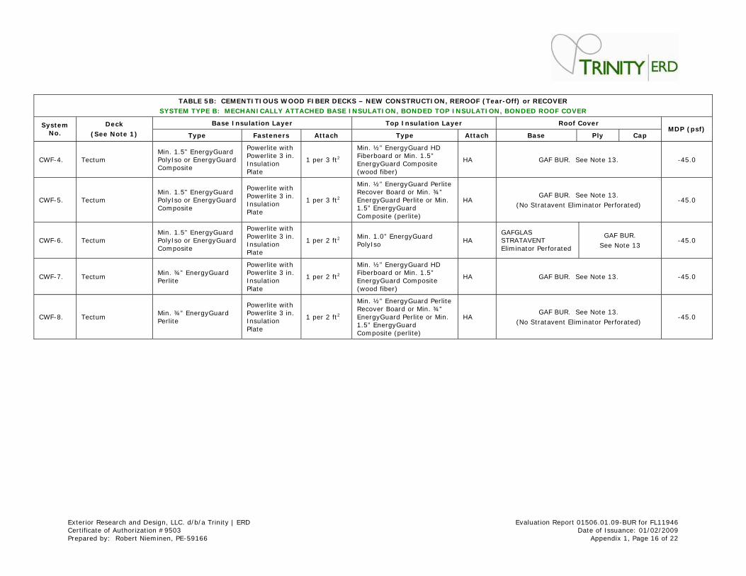
TABLE 5 B: CEMENTI TI OUS W OOD FI BER DECKS – NE W CONSTRUCTI ON, REROOF ( Tear- Off) or RECOVER
SYSTEM TYPE B: MECHANI CALLY ATTACHED BASE I NSU LATI ON, BONDED TOP I NSULATI ON, BONDED ROOF COVER
Base I nsulat ion Layer Top I nsulat ion Layer Roof Cov er System No.
Deck
( See Note 1 ) Type Fasteners At tach Type At tach Base Ply Cap MDP ( psf)
CWF-4. Tectum Min. 1.5” EnergyGuard PolyI so or EnergyGuard Composite
Powerlite with Powerlite 3 in. I nsulat ion Plate
1 per 3 ft 2
Min. ½” EnergyGuard HD Fiberboard or Min. 1.5” EnergyGuard Com posite (wood fiber)
HA GAF BUR. See Note 13. -45.0
CWF-5. Tectum Min. 1.5” EnergyGuard PolyI so or EnergyGuard Composite
Powerlite with Powerlite 3 in. I nsulat ion Plate
1 per 3 ft 2
Min. ½” EnergyGuard Perlite Recover Board or Min. ¾” EnergyGuard Perlite or Min. 1.5” EnergyGuard Composite (perlite)
HA GAF BUR. See Note 13.
(No St ratavent Elim inator Perforated) -45.0
CWF-6. Tectum Min. 1.5” EnergyGuard PolyI so or EnergyGuard Composite
Powerlite with Powerlite 3 in. I nsulat ion Plate
1 per 2 ft 2 Min. 1.0” EnergyGuard PolyI so
HA GAFGLAS STRATAVENT Elim inator Perforated
GAF BUR.
See Note 13 -45.0
CWF-7. Tectum Min. ¾” EnergyGuard Perlite
Powerlite with Powerlite 3 in. I nsulat ion Plate
1 per 2 ft 2
Min. ½” EnergyGuard HD Fiberboard or Min. 1.5” EnergyGuard Com posite (wood fiber)
HA GAF BUR. See Note 13. -45.0
CWF-8. Tectum Min. ¾” EnergyGuard Perlite
Powerlite with Powerlite 3 in. I nsulat ion Plate
1 per 2 ft 2
Min. ½” EnergyGuard Perlite Recover Board or Min. ¾” EnergyGuard Perlite or Min. 1.5” EnergyGuard Composite (perlite)
HA GAF BUR. See Note 13.
(No St ratavent Elim inator Perforated) -45.0
Exterior Research and Design, LLC. d/ b/ a Trinity | ERD Evaluat ion Report 01506.01.09-BUR for FL11946 Cert ificate of Authorizat ion # 9503 Date of I ssuance: 01/ 02/ 2009 Prepared by: Robert Niem inen, PE-59166 Appendix 1, Page 17 of 22
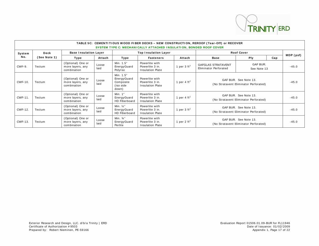
TABLE 5 C: CEMENTI TI OUS W OOD FI BER DECKS – NE W CONSTRUCTI ON, REROOF ( Tear- Off) or RECOVER
SYSTEM TYPE C: MECHANI CALLY ATTACHED I NSULATI ON, BO NDED ROOF COVER
Base I nsulat ion Layer Top I nsulat ion Layer Roof Cover System No.
Deck
( See Note 1 ) Type At tach Type Fasteners At tach Base Ply Cap MDP ( psf)
CWF-9. Tectum (Opt ional) One or m ore layers, any com binat ion
Loose laid
Min. 1.5” EnergyGuard PolyI so
Powerlite with Powerlite 3 in. I nsulat ion Plate
1 per 3 ft 2 GAFGLAS STRATAVENT Elim inator Perforated
GAF BUR.
See Note 13 -45.0
CWF-10. Tectum (Opt ional) One or m ore layers, any com binat ion
Loose laid
Min. 1.5” EnergyGuard Composite ( iso side down)
Powerlite with Powerlite 3 in. I nsulat ion Plate
1 per 4 ft 2 GAF BUR. See Note 13.
(No St ratavent Elim inator Perforated) -45.0
CWF-11. Tectum (Opt ional) One or m ore layers, any com binat ion
Loose laid
Min. 1” EnergyGuard HD Fiberboard
Powerlite with Powerlite 3 in. I nsulat ion Plate
1 per 4 ft 2 GAF BUR. See Note 13.
(No St ratavent Elim inator Perforated) -45.0
CWF-12. Tectum (Opt ional) One or m ore layers, any com binat ion
Loose laid
Min. ½” EnergyGuard HD Fiberboard
Powerlite with Powerlite 3 in. I nsulat ion Plate
1 per 3 ft 2 GAF BUR. See Note 13.
(No St ratavent Elim inator Perforated) -45.0
CWF-13. Tectum (Opt ional) One or m ore layers, any com binat ion
Loose laid
Min. ¾” EnergyGuard Perlite
Powerlite with Powerlite 3 in. I nsulat ion Plate
1 per 2 ft 2 GAF BUR. See Note 13.
(No St ratavent Elim inator Perforated) -45.0
Exterior Research and Design, LLC. d/ b/ a Trinity | ERD Evaluat ion Report 01506.01.09-BUR for FL11946 Cert ificate of Authorizat ion # 9503 Date of I ssuance: 01/ 02/ 2009 Prepared by: Robert Niem inen, PE-59166 Appendix 1, Page 18 of 22
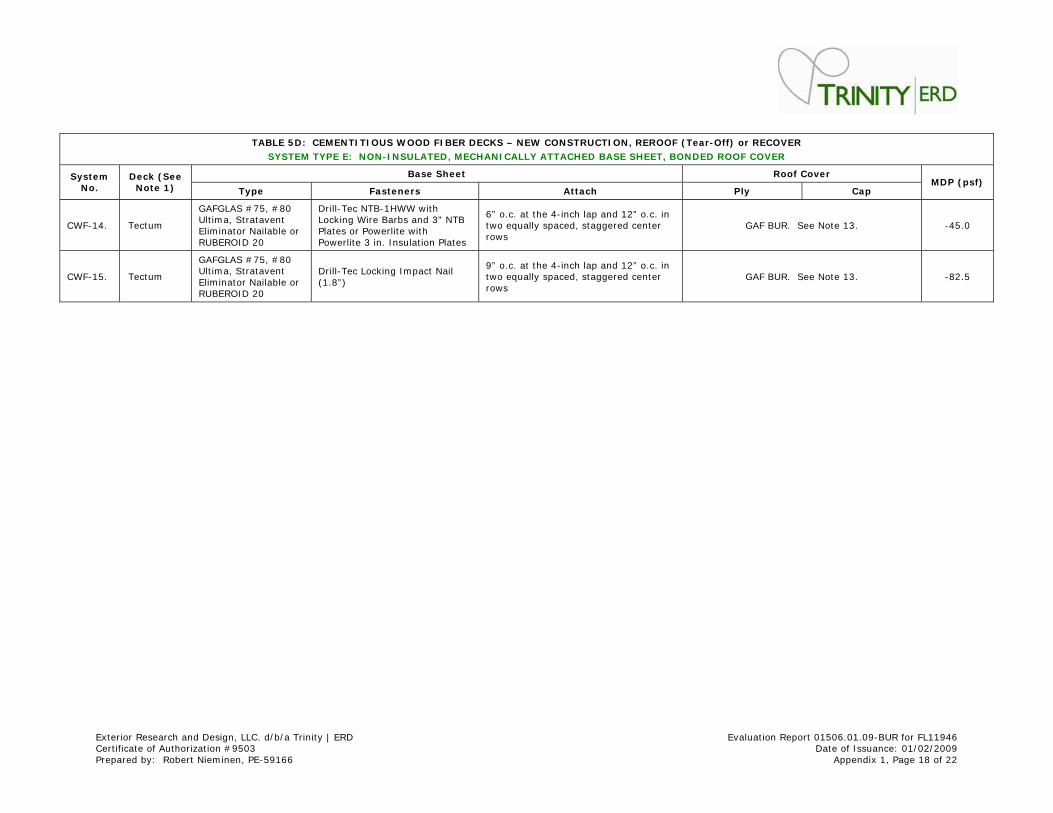
TABLE 5 D: CEMENTI TI OUS W OOD FI BER DECKS – NE W CONSTRUCTI ON, REROOF ( Tear- Off) or RECOVER
SYSTEM TYPE E: NON- I NSULATED, MECHANI CALLY ATTACHED BASE SHEET, BONDED ROOF COVER
Base Sheet Roof Cover System No.
Deck ( See Note 1 ) Type Fasteners At tach Ply Cap
MDP ( psf)
CWF-14. Tectum
GAFGLAS # 75, # 80 Ult im a, St ratavent Elim inator Nailable or RUBEROI D 20
Drill-Tec NTB-1HWW with Locking Wire Barbs and 3” NTB Plates or Powerlite with Powerlite 3 in. I nsulat ion Plates
6” o.c. at the 4- inch lap and 12” o.c. in two equally spaced, staggered center rows
GAF BUR. See Note 13. -45.0
CWF-15. Tectum
GAFGLAS # 75, # 80 Ult im a, St ratavent Elim inator Nailable or RUBEROI D 20
Drill-Tec Locking I m pact Nail (1.8” )
9” o.c. at the 4- inch lap and 12” o.c. in two equally spaced, staggered center rows
GAF BUR. See Note 13. -82.5
Exterior Research and Design, LLC. d/ b/ a Trinity | ERD Evaluat ion Report 01506.01.09-BUR for FL11946 Cert ificate of Authorizat ion # 9503 Date of I ssuance: 01/ 02/ 2009 Prepared by: Robert Niem inen, PE-59166 Appendix 1, Page 19 of 22
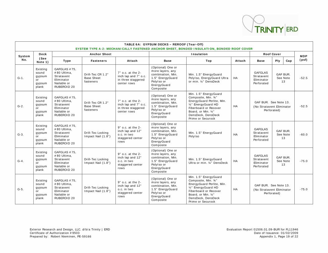
TABLE 6 A: GYPSUM DECKS – REROOF ( Tear- Off)
SYSTEM TYPE A- 2 : MECHANI CALLY FASTENED ANCHOR SHEET, BONDED I NSULATI ON, BONDED ROOF COVER
Anchor Sheet I nsulat ion Roof Cover System
No.
Deck
( See Note 1 ) Type Fasteners At tach Base Top At tach Base Ply Cap
MDP ( psf)
G-1.
Exist ing sound gypsum or gypsum plank
GAFGLAS # 75, # 80 Ult ima, St ratavent Elim inator Nailable or RUBEROI D 20
Drill-Tec CR 1.2” Base Sheet fasteners
7” o.c. at the 2-inch lap and 7” o.c. in three staggered center rows
(Opt ional) One or m ore layers, any com binat ion, Min. 1.5” EnergyGuard PolyI so or EnergyGuard Composite
Min. 1.5” EnergyGuard PolyI so, EnergyGuard Ult ra or m in. ¼” DensDeck
HA
GAFGLAS St ratavent Elim inator Perforated
GAF BUR. See Note
13 -52.5
G-2.
Exist ing sound gypsum or gypsum plank
GAFGLAS # 75, # 80 Ult ima, St ratavent Elim inator Nailable or RUBEROI D 20
Drill-Tec CR 1.2” Base Sheet fasteners
7” o.c. at the 2-inch lap and 7” o.c. in three staggered center rows
(Opt ional) One or m ore layers, any com binat ion, Min. 1.5” EnergyGuard PolyI so or EnergyGuard Composite
Min. 1.5” EnergyGuard Composite, Min. ¾” EnergyGuard Perlite, Min. ½” EnergyGuard HD Fiberboard or Recover Board, or Min. ¼” DensDeck, DensDeck Prime or Securock
HA GAF BUR. See Note 13.
(No St ratavent Elim inator Perforated)
-52.5
G-3.
Exist ing sound gypsum or gypsum plank
GAFGLAS # 75, # 80 Ult ima, St ratavent Elim inator Nailable or RUBEROI D 20
Drill-Tec Locking I mpact Nail (1.8” )
9” o.c. at the 2-inch lap and 12” o.c. in two staggered center rows
(Opt ional) One or m ore layers, any com binat ion, Min. 1.5” EnergyGuard PolyI so or EnergyGuard Composite
Min. 1.5” EnergyGuard PolyI so
HA
GAFGLAS St ratavent Elim inator Perforated
GAF BUR. See Note
13 -60.0
G-4.
Exist ing sound gypsum or gypsum plank
GAFGLAS # 75, # 80 Ult ima, St ratavent Elim inator Nailable or RUBEROI D 20
Drill-Tec Locking I mpact Nail (1.8” )
9” o.c. at the 2-inch lap and 12” o.c. in two staggered center rows
(Opt ional) One or m ore layers, any com binat ion, Min. 1.5” EnergyGuard PolyI so or EnergyGuard Composite
Min. 1.5” EnergyGuard Ult ra or m in. ¼” DensDeck
HA
GAFGLAS St ratavent Elim inator Perforated
GAF BUR. See Note
13 -75.0
G-5.
Exist ing sound gypsum or gypsum plank
GAFGLAS # 75, # 80 Ult ima, St ratavent Elim inator Nailable or RUBEROI D 20
Drill-Tec Locking I mpact Nail (1.8” )
9” o.c. at the 2-inch lap and 12” o.c. in two staggered center rows
(Opt ional) One or m ore layers, any com binat ion, Min. 1.5” EnergyGuard PolyI so or EnergyGuard Composite
Min. 1.5” EnergyGuard Composite, Min. ¾” EnergyGuard Perlite, Min. ½” EnergyGuard HD Fiberboard or Recover Board, or Min. ¼” DensDeck, DensDeck Prime or Securock
HA GAF BUR. See Note 13.
(No St ratavent Elim inator Perforated)
-75.0
Exterior Research and Design, LLC. d/ b/ a Trinity | ERD Evaluat ion Report 01506.01.09-BUR for FL11946 Cert ificate of Authorizat ion # 9503 Date of I ssuance: 01/ 02/ 2009 Prepared by: Robert Niem inen, PE-59166 Appendix 1, Page 20 of 22
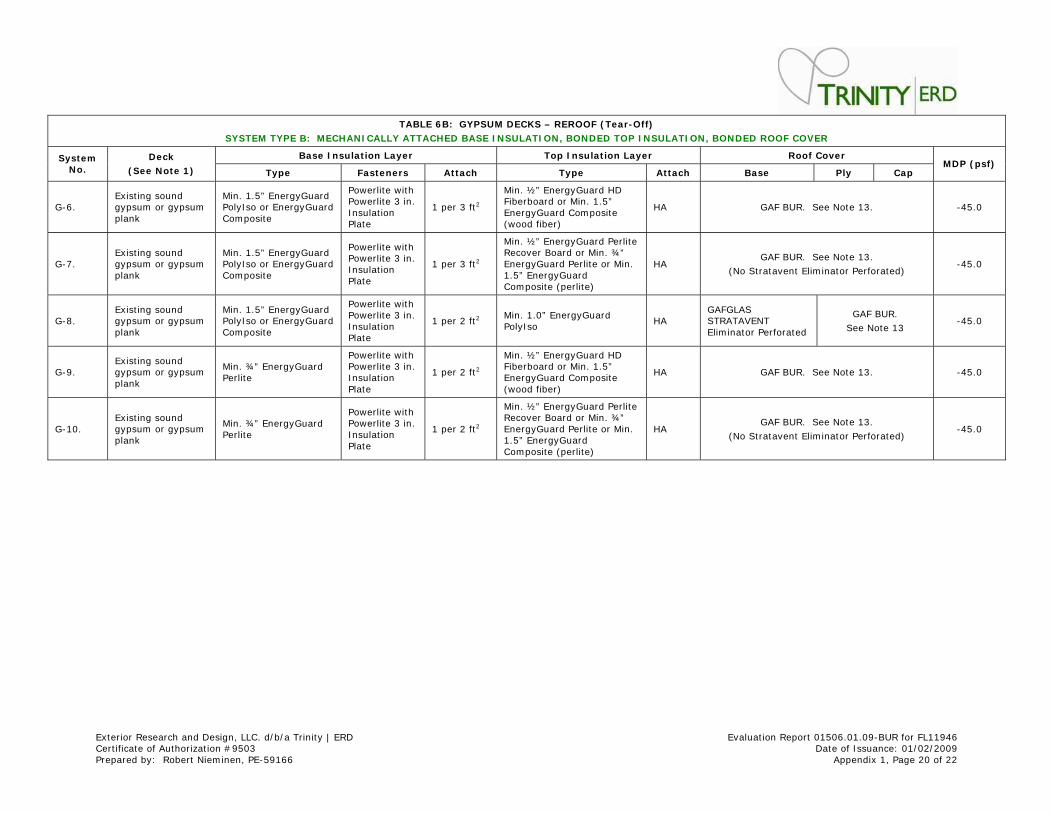
TABLE 6 B: GYPSUM DECKS – REROOF ( Tear- Off)
SYSTEM TYPE B: MECHANI CALLY ATTACHED BASE I NSU LATI ON, BONDED TOP I NSULATI ON, BONDED ROOF COVER
Base I nsulat ion Layer Top I nsulat ion Layer Roof Cov er System No.
Deck
( See Note 1 ) Type Fasteners At tach Type At tach Base Ply Cap MDP ( psf)
G-6. Exist ing sound gypsum or gypsum plank
Min. 1.5” EnergyGuard PolyI so or EnergyGuard Composite
Powerlite with Powerlite 3 in. I nsulat ion Plate
1 per 3 ft 2
Min. ½” EnergyGuard HD Fiberboard or Min. 1.5” EnergyGuard Com posite (wood fiber)
HA GAF BUR. See Note 13. -45.0
G-7. Exist ing sound gypsum or gypsum plank
Min. 1.5” EnergyGuard PolyI so or EnergyGuard Composite
Powerlite with Powerlite 3 in. I nsulat ion Plate
1 per 3 ft 2
Min. ½” EnergyGuard Perlite Recover Board or Min. ¾” EnergyGuard Perlite or Min. 1.5” EnergyGuard Composite (perlite)
HA GAF BUR. See Note 13.
(No St ratavent Elim inator Perforated) -45.0
G-8. Exist ing sound gypsum or gypsum plank
Min. 1.5” EnergyGuard PolyI so or EnergyGuard Composite
Powerlite with Powerlite 3 in. I nsulat ion Plate
1 per 2 ft 2 Min. 1.0” EnergyGuard PolyI so
HA GAFGLAS STRATAVENT Elim inator Perforated
GAF BUR.
See Note 13 -45.0
G-9. Exist ing sound gypsum or gypsum plank
Min. ¾” EnergyGuard Perlite
Powerlite with Powerlite 3 in. I nsulat ion Plate
1 per 2 ft 2
Min. ½” EnergyGuard HD Fiberboard or Min. 1.5” EnergyGuard Com posite (wood fiber)
HA GAF BUR. See Note 13. -45.0
G-10. Exist ing sound gypsum or gypsum plank
Min. ¾” EnergyGuard Perlite
Powerlite with Powerlite 3 in. I nsulat ion Plate
1 per 2 ft 2
Min. ½” EnergyGuard Perlite Recover Board or Min. ¾” EnergyGuard Perlite or Min. 1.5” EnergyGuard Composite (perlite)
HA GAF BUR. See Note 13.
(No St ratavent Elim inator Perforated) -45.0
Exterior Research and Design, LLC. d/ b/ a Trinity | ERD Evaluat ion Report 01506.01.09-BUR for FL11946 Cert ificate of Authorizat ion # 9503 Date of I ssuance: 01/ 02/ 2009 Prepared by: Robert Niem inen, PE-59166 Appendix 1, Page 21 of 22
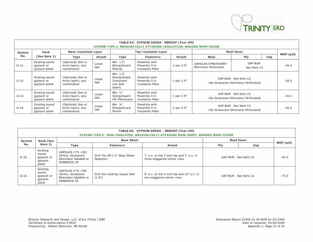
TABLE 6 C: GYPSUM DECKS - REROOF ( Tear- Off)
SYSTEM TYPE C: MECHANI CALLY ATTACHED I NSULATI ON, BO NDED ROOF COVER
Base I nsulat ion Layer Top I nsulat ion Layer Roof Cover System No.
Deck
( See Note 1 ) Type At tach Type Fasteners At tach Base Ply Cap MDP ( psf)
G-11. Exist ing sound gypsum or gypsum plank
(Opt ional) One or m ore layers, any com binat ion
Loose laid
Min. 1.5” EnergyGuard PolyI so
Powerlite with Powerlite 3 in. I nsulat ion Plate
1 per 2 ft 2 GAFGLAS STRATAVENT Elim inator Perforated
GAF BUR.
See Note 13 -45.0
G-12. Exist ing sound gypsum or gypsum plank
(Opt ional) One or m ore layers, any com binat ion
Loose laid
Min. 1.5” EnergyGuard Composite ( iso side down)
Powerlite with Powerlite 3 in. I nsulat ion Plate
1 per 2 ft 2 GAF BUR. See Note 13.
(No St ratavent Elim inator Perforated) -45.0
G-13. Exist ing sound gypsum or gypsum plank
(Opt ional) One or m ore layers, any com binat ion
Loose laid
Min. ½” EnergyGuard HD Fiberboard
Powerlite with Powerlite 3 in. I nsulat ion Plate
1 per 2 ft 2 GAF BUR. See Note 13.
(No St ratavent Elim inator Perforated) -45.0
G-14. Exist ing sound gypsum or gypsum plank
(Opt ional) One or m ore layers, any com binat ion
Loose laid
Min. ¾” EnergyGuard Perlite
Powerlite with Powerlite 3 in. I nsulat ion Plate
1 per 2 ft 2 GAF BUR. See Note 13.
(No St ratavent Elim inator Perforated) -45.0
TABLE 6 D: GYPSUM DECKS – REROOF ( Tear-Off)
SYSTEM TYPE E: NON- I NSULATED, MECHANI CALLY ATTACHED BASE SHEET, BONDED ROOF COVER
Base Sheet Roof Cover System No.
Deck ( See Note 1 ) Type Fasteners At tach Ply Cap
MDP ( psf)
G-15.
Exist ing sound gypsum or gypsum plank
GAFGLAS # 75, # 80 Ult im a, St ratavent Elim inator Nailable or RUBEROI D 20
Drill-Tec CR 1.2” Base Sheet fasteners
7” o.c. at the 2- inch lap and 7” o.c. in three staggered center rows
GAF BUR. See Note 13. -45.0
G-16.
Exist ing sound gypsum or gypsum plank
GAFGLAS # 75, # 80 Ult im a, St ratavent Elim inator Nailable or RUBEROI D 20
Drill-Tec Locking I m pact Nail (1.8” )
9” o.c. at the 2- inch lap and 12” o.c. in two staggered center rows
GAF BUR. See Note 13. -75.0
Exterior Research and Design, LLC. d/ b/ a Trinity | ERD Evaluat ion Report 01506.01.09-BUR for FL11946 Cert ificate of Authorizat ion # 9503 Date of I ssuance: 01/ 02/ 2009 Prepared by: Robert Niem inen, PE-59166 Appendix 1, Page 22 of 22
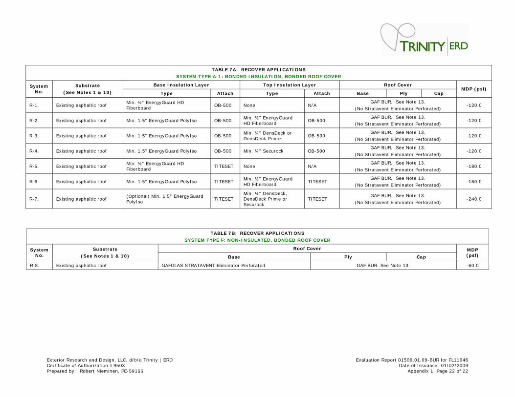
TABLE 7 A: RECOVER APPLI CATI ONS
SYSTEM TYPE A- 1 : BONDED I NSULATI ON, BONDED ROOF COV ER
Base I nsulat ion Layer Top I nsulat ion Layer Roof Cov er System No.
Subst ra te
( See Notes 1 & 1 0 ) Type At tach Type At tach Base Ply Cap MDP ( psf)
R-1. Exist ing asphalt ic roof Min. ½” EnergyGuard HD Fiberboard
OB-500 None N/ A GAF BUR. See Note 13.
(No St ratavent Elim inator Perforated) -120.0
R-2. Exist ing asphalt ic roof Min. 1.5” EnergyGuard PolyI so OB-500 Min. ½” EnergyGuard HD Fiberboard
OB-500 GAF BUR. See Note 13.
(No St ratavent Elim inator Perforated) -120.0
R-3. Exist ing asphalt ic roof Min. 1.5” EnergyGuard PolyI so OB-500 Min. ¼” DensDeck or DensDeck Prime
OB-500 GAF BUR. See Note 13.
(No St ratavent Elim inator Perforated) -120.0
R-4. Exist ing asphalt ic roof Min. 1.5” EnergyGuard PolyI so OB-500 Min. ¼” Securock OB-500 GAF BUR. See Note 13.
(No St ratavent Elim inator Perforated) -120.0
R-5. Exist ing asphalt ic roof Min. ½” EnergyGuard HD Fiberboard
TI TESET None N/ A GAF BUR. See Note 13.
(No St ratavent Elim inator Perforated) -180.0
R-6. Exist ing asphalt ic roof Min. 1.5” EnergyGuard PolyI so TI TESET Min. ½” EnergyGuard HD Fiberboard
TI TESET GAF BUR. See Note 13.
(No St ratavent Elim inator Perforated) -180.0
R-7. Exist ing asphalt ic roof (Opt ional) Min. 1.5” EnergyGuard PolyI so
TI TESET Min. ¼” DensDeck, DensDeck Prime or Securock
TI TESET GAF BUR. See Note 13.
(No St ratavent Elim inator Perforated) -240.0
TABLE 7 B: RECOVER APPLI CATI ONS
SYSTEM TYPE F: NON- I NSULATED, BONDED ROOF COVER
Roof Cover System No.
Subst ra te
( See Notes 1 & 1 0 ) Base Ply Cap
MDP ( psf)
R-8. Exist ing asphalt ic roof GAFGLAS STRATAVENT Elim inator Perforated GAF BUR. See Note 13. -60.0


