Trimble Business Center - HCE Handbook 10/18/2017 1 | Page Florida Department of Transportation Trimble Business Center – Heavy Construction Edition (HCE) Version 3.9 Version Change Made By Date
Transcript
Trimble Business Center - HCE Handbook 10/18/2017
1 | P a g e
Florida Department of Transportation
Trimble Business Center – Heavy Construction Edition (HCE)
The purpose of this document is provide guidance on how to use basic functions of Trimble Business Center – HCE (Trimble) Version 3.9 to calculate earthwork quantities for Final Estimates purposes.
All graphics shown in the User Guide are from Trimble Business Center – HCE (Trimble) Version 3.9; however, the procedures to use these basic functions should be similar for all versions. It is the user’s responsibility to learn the necessary functions for the applicable version which is being used. See the Additional Trimble Resources section for further guidance.
Software Information
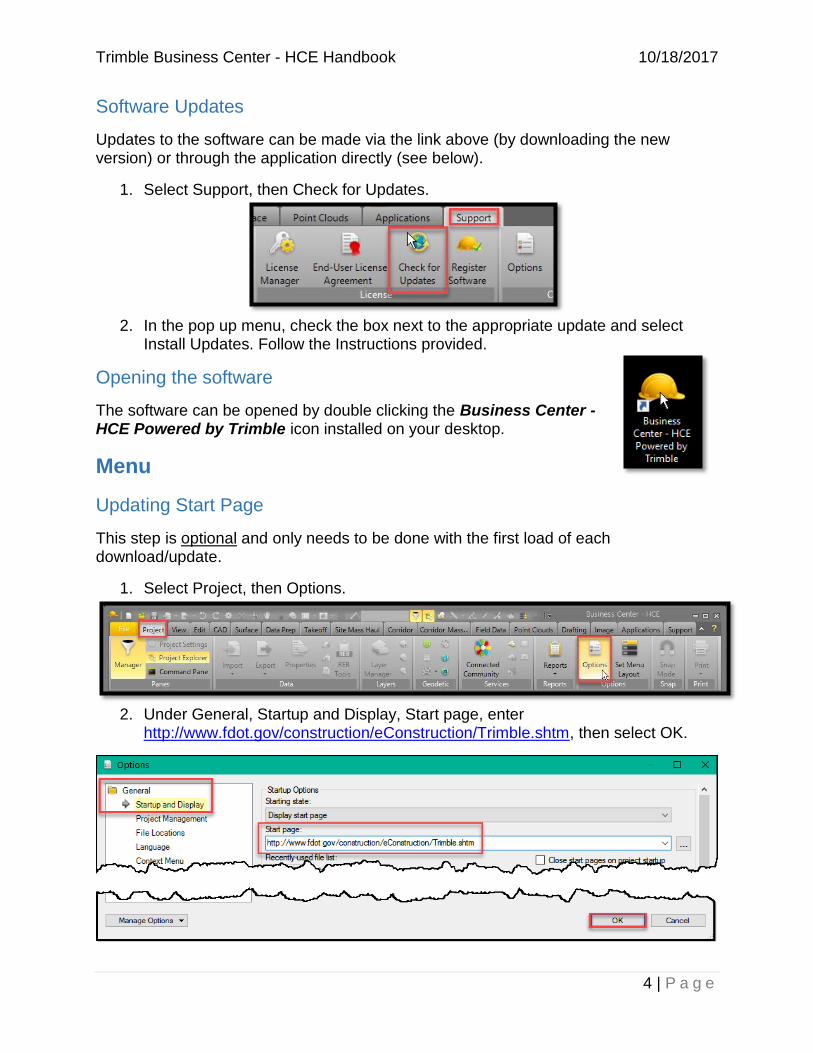
Software Download
The core software product can be downloaded and installed for free from https://construction.trimble.com/products-and-solutions/business-center-hce.
System Requirements
Prior to installing the software, ensure your computer meets the recommended System Requirements (listed below and found on link above). Trimble may run on a system with less than recommended requirements, but performance will be poor and likely unacceptable.
Minimum System Requirements:
2.2GHZ Processor
DirectX Graphics Card (with most updated video drivers)
NOTE: This link is the FDOT Trimble webpage. Additional information and Frequently Asked Questions will be posted here, so using this as your start page will give you direct access to any updates. Also, see the Additional Trimble Resources section for more information.
Updating the Ribbon
This step is optional and only needs to be done with the first load of each download/update.
Trimble has an extensive array of licenses that can be purchased to perform many different functions. The primary functions needed by FDOT are covered by the free Core Product; therefore, many of the ribbon buttons are not necessary and will either be grayed out or, when clicked, will pop up with a box to purchase a new module.
In order to simplify the FDOT user experience, the Department has created a customized FDOT ribbon that can be downloaded from the FDOT Trimble Resource link and imported into Trimble. This will reduce the number of tabs available, leaving only the ones required to perform functions needed by FDOT.
1. After downloading the FDOT Custom Menu file, right click anywhere on the ribbon, then select Customize Ribbon.
2. Select Import, then navigate to and select the FDOT Custom Menu file and click
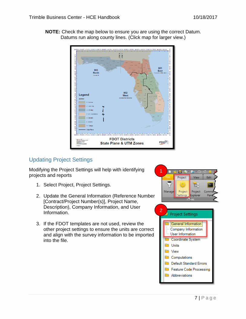
NOTE: Check the map below to ensure you are using the correct Datum. Datums run along county lines. (Click map for larger view.)
Updating Project Settings
Modifying the Project Settings will help with identifying projects and reports
1. Select Project, Project Settings.
2. Update the General Information (Reference Number [Contract/Project Number(s)], Project Name, Description), Company Information, and User Information.
3. If the FDOT templates are not used, review the other project settings to ensure the units are correct and align with the survey information to be imported into the file.
2. On the Import tab, select the files to import, then select Import.
NOTE: Use only LandXML Format, if possible.
2
12
Trimble Business Center - HCE Handbook 10/18/2017
9 | P a g e
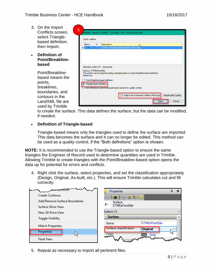
3. On the Import Conflicts screen, select Triangle-based definition, then Import.
Definition of Point/Breakline-based
Point/Breakline-based means the points, breaklines, boundaries, and contours in the LandXML file are used by Trimble to create the surface. This data defines the surface, but the data can be modified, if needed.
Definition of Triangle-based
Triangle-based means only the triangles used to define the surface are imported. This data becomes the surface and it can no longer be edited. This method can be used as a quality control, if the “Both definitions” option is chosen.
NOTE: It is recommended to use the Triangle-based option to ensure the same triangles the Engineer of Record used to determine quantities are used in Trimble. Allowing Trimble to create triangles with the Point/Breakline-based option opens the data up for potential for errors and conflicts.
4. Right click the surface, select properties, and set the classification appropriately (Design, Original, As-built, etc.). This will ensure Trimble calculates cut and fill correctly.
5. Repeat as necessary to import all pertinent files.
3
Trimble Business Center - HCE Handbook 10/18/2017
10 | P a g e
Naming Conventions
Ensure all Trimble files and new features (surfaces, corridors, layers, etc) within Trimble have descriptive titles (subsoil, final, intermediate, etc) along with the Contract Number and Financial Project Number.
Example Trimble File Submittal Naming Convention: T1234_987651-1-52-01.vce
Example Surface Naming Convention: T1234_987654-1-52-01_Subsoil_Final.xml
Example Layer Name: Subsoil_Final
Viewing the Flags Pane
The Flags Pane shows import or computation errors. Flagged objects should be analyzed to see why the objects were flagged and if it warrants further attention.
To view the Flags Pane, click the icon in the status bar across the bottom of the screen.
When reviewing the Flags pane, double click on any line item and it will take you to where the error is located in the model. Flags within your project will identify the location of each error as well.
NOTE: The Flag pane only shows the top 100 flags for each surface in the model. As you resolve flags, more flags may appear until you eliminate all the flags. Typical flags will be found where two surface breaklines cross, but have different elevations for the same location. Trimble will form a surface model and assume that one of the two options is correct and will flag the difference. Trimble may assume that the wrong one is correct, so it is the user’s responsibility to ensure that the model is correct.
Calculating Surface to Surface Volumes (No Boundary)
This method of generating an Earthwork Report will calculate earthwork quantities without a user defined boundary; thereby making the default boundary limits equal to the limits of the outer boundaries of the surfaces being compared.
Trimble Business Center - HCE Handbook 10/18/2017
11 | P a g e
Definition of a Surface
A surface is generated by connecting data points into triangles to create a 3D model.
1. Select Surface, then Earthwork Report.
2. On the Earthwork Report tab, select Surface to Surface, select the initial and final surfaces (i.e. the 2 surfaces to compare).
NOTE: The surface names that appear under ‘Initial’ and ‘Final’ are the actual names of the surfaces (within the surface files) and not necessarily the names of the surface files that were imported.
a. Typically, you will be comparing the
design files to your pre-construction survey, or your design files to your post-construction survey.
b. In the case of subsoil, you will be comparing the bottom of subsoil excavation to the top of fill. You will also need to compare the bottom of subsoil to the design files to see if the tolerances in Specifications Section 120-4.1 were exceeded and compare the top of fill to the finished grading template, as defined in Specifications Section 120-2.3. Use the 1:2 control line shown in Design Standard Index 500 to determine the limit for removal.
3. It is not recommended to use the Materials option as it isn’t needed for final estimate payment. This option can be useful for Contractors when determining if material is usable in other locations on the project.
4. Under Volume Breakdown, select your preferred reporting option. (See next page for options.)
1vghf
3
4
2
Trimble Business Center - HCE Handbook 10/18/2017
12 | P a g e
a. Volume totals only – report will give you the amount of cut, fill, and excess/shortage. (Example below)
b. By depth increment – report will give cut and fill based on the depth increment entered, along with the volume totals. (Example below is depth increment = 5)
c. By elevation interval, report will give you cut and fill based on the elevation interval and index elevation entered, along with the volume totals. (Example below is elevation range = 1 and index elevation = 0.)
5. Click OK to generate the Earthwork Report based on your preferred option for volume breakdown.
NOTE: Always review the surfaces and surface classifications being compared to ensure that the Cut / Fill quantities are reported correctly.
Trimble Business Center - HCE Handbook 10/18/2017
13 | P a g e
Calculating Surface to Surface Volumes (with Boundary)
It may be beneficial or necessary to generate an earthwork report within isolated areas on the project.
Definition of Boundary
A boundary delineates a portion of a surface to limit the calculation to a specific area or section of the surface. Boundaries can be defined by creating/using shapes, polylines, or corridors within the project limits.
1. Follow the steps for Calculating Surface to Surface Volumes, but in the Boundary cell, select the boundary line to limit your calculation, then select OK.
NOTE: The boundary can be various shapes (see Create a Circle, Create a Rectangle, and Create a Polyline. The boundary must be a closed shape to limit the calculation correctly. Also, boundaries only need to be in 2-D (no elevation required). Be aware however, that “no elevation” is like 0 elevation, so the boundary will be at a different elevation as the surface when viewing in 3-D. A boundary acts as a “cookie cutter” through the selected surfaces and limits the volumes computed to that which fall inside of the boundary.
1
Trimble Business Center - HCE Handbook 10/18/2017
14 | P a g e
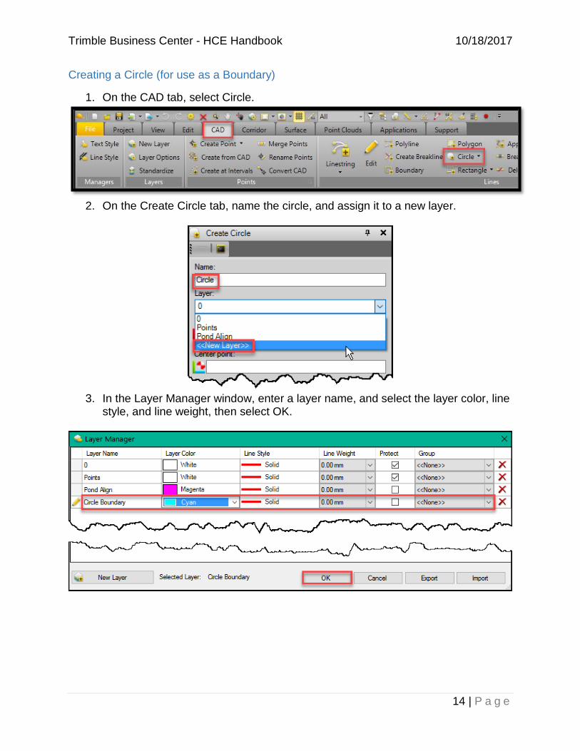
Creating a Circle (for use as a Boundary)
1. On the CAD tab, select Circle.
2. On the Create Circle tab, name the circle, and assign it to a new layer.
3. In the Layer Manager window, enter a layer name, and select the layer color, line
style, and line weight, then select OK.
Trimble Business Center - HCE Handbook 10/18/2017
15 | P a g e
4. Optional: Enter the circle Elevation or snap to any 3d object to specify the elevation. (See Definition of Boundary – elevation is not required.)
5. Enter a coordinate or select a point on the surface as the Center point of the circle.
6. Enter the radius or select a point on the surface to specify the circle size.
7. Once a radius is selected, the Create Circle tab is ready to make a new circle. If you are done making a circle, select Close. If you need another circle, repeat the Create Circle steps above.
NOTE: Once a boundary is created, it can be used to generate a surface to surface volume report.
Creating a Rectangle (for use as a Boundary)
1. On the CAD tab, select Rectangle.
NOTE: The rectangle command creates a rectangle in the N-S, E-W orientation. To skew a rectangle, use the pull down on the icon and select 3-point rectangle. This allows selection of two points and a width to define the rectangle (See Step 8).
4
5
6
7
Trimble Business Center - HCE Handbook 10/18/2017
16 | P a g e
2. On the Create Rectangle tab, name the rectangle, and assign it to a new layer.
3. In the Layer Manager window, enter a layer name, and select the layer color, line style, and line weight, then select OK.
Trimble Business Center - HCE Handbook 10/18/2017
17 | P a g e
4. Optional: Enter the rectangle Elevation or snap to any 3d object to specify the elevation. (See Definition of Boundary – elevation is not necessary).
5. Enter a coordinate or select a point on the surface as Corner one.
6. Enter a coordinate or select a point on the surface as Corner two.
7. Once Corner two is selected, the Create Rectangle tab is ready to make a new rectangle. If you are done making a rectangle, select Close. If you need another rectangle, repeat the Create Rectangle steps above.
8. For a Three-Point Rectangle, select the width and then Close.
NOTE: Once a boundary is created, it can be used to generate a surface to surface volume report.
4
5
6
7
8
Trimble Business Center - HCE Handbook 10/18/2017
18 | P a g e
Creating a Polyline (for use as a Boundary)
1. On the CAD tab, select Polyline.
2. On the Create Polyline tab, name the polyline and assign it to a new layer.
3. Select Always to automatically close by connecting ends, since the boundary needs to be closed.
4. Select the appropriate Method to Add Points.
Definition of Specify Individual Points
The start and end points for each segment can be selected.
Definition of Stream points
The first point of the polyline can be selected, then points are selected as you move along the path with the mouse button down based on the filter settings.
3
4
Trimble Business Center - HCE Handbook 10/18/2017
19 | P a g e
5. The last option of the Create Polyline tab is dependent upon the selection for Method to Add Points.
6. Add points and then Close.
NOTE: Once a boundary is created, it can be used to generate a surface to surface volume report.
Viewing Cross Sections
First, you must have a corridor with an alignment to create cross sections. Design files will come with a corridor and alignment already defined. If you have a project that does not have a corridor and alignment, you will need to create them (See Creating an Alignment and Creating a Corridor).
1. Select Corridor, then Cross-Section View. You must have a corridor or alignment selected for the Cross-Section View icon to be selectable.
2. At the bottom of the screen, type in the station value or move the slider to the
station to view. Use the yellow wheel icon, to change the station interval.
2
1
Trimble Business Center - HCE Handbook 10/18/2017
20 | P a g e
Creating an Alignment
Definition of Alignment
An Alignment defines the path or route of a road based on a series of tangents and curves. There are two alignments for every road – the horizontal alignment and the vertical alignment. The horizontal alignment typically follows the centerline of the road. The vertical alignment follows the horizontal alignment, but indicates the elevation to show whether you are going up or down a hill.
1. Select Corridor, Create Alignment.
2. Enter the name of the alignment and select the layer on the Create Alignment
tab.
3. Select the applicable Horizontal Geometry Definition, then select OK.
Definition of Inscribe curves at PIs
This option builds the alignment from data with values for curves at consecutive Points of Intersection (PIs).
Definition of Define individual segments
This option builds the alignment from data with values for consecutive line, arc, and spiral segments or to build an alignment based on the geometry of an existing line.
1
3
2
Trimble Business Center - HCE Handbook 10/18/2017
21 | P a g e
Creating a Corridor
Definition of Corridor
A Corridor is a 3D model of a road based on the horizontal and vertical alignments identified.
1. On the Corridor tab, select Create Corridor.
2. On the Create Corridor tab, name the corridor and select the horizontal alignment. Select the appropriate original ground file and check the same original ground file in the “reference surfaces” section at the bottom of the window, click OK.
NOTE: It is unnecessary to select a vertical alignment or native and fill materials.
3. On the Insert Corridor Template tab, select a beginning station for the new corridor and click Insert.
1
2
3
Trimble Business Center - HCE Handbook 10/18/2017
22 | P a g e
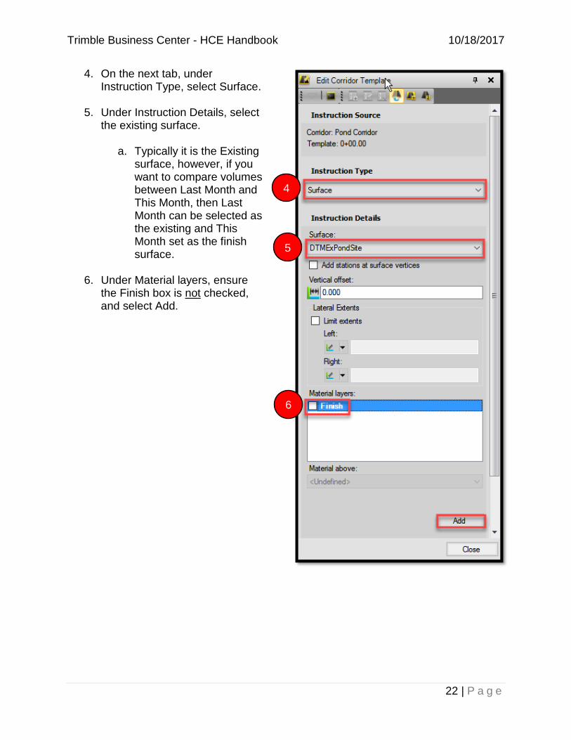
4. On the next tab, under Instruction Type, select Surface.
5. Under Instruction Details, select the existing surface.
a. Typically it is the Existing surface, however, if you want to compare volumes between Last Month and This Month, then Last Month can be selected as the existing and This Month set as the finish surface.
6. Under Material layers, ensure
the Finish box is not checked, and select Add.
4
5
6
Trimble Business Center - HCE Handbook 10/18/2017
23 | P a g e
7. On the next tab, under Instruction Details, select the proposed surface to compare with the original ground.
8. Under Material Layers, select the Finish box, and click Add.
9. Trimble will produce cross sections with cut and fill areas between the two surfaces in the corridor.
NOTE: It is now possible to generate Corridor Earthwork Reports along the corridor.
8
7
9
Trimble Business Center - HCE Handbook 10/18/2017
24 | P a g e
Generating a Corridor Earthwork Report (with Option for Subsection/ Between Stations)
1. On the Corridor tab, select Corridor Earthwork.
2. Choose appropriate corridor for
analysis.
3. Specify station increment.
4. Optional Clipping Boundaries will be automatically set to “Selected: 1”. Ensure it is set to “Selected: 0”.
5. To produce the Corridor Earthwork Report for a specific section of the project, enter the start and end station values for the section to be analyzed.
6. Uncheck the horizontal and vertical points to produce earthwork quantities only for the specified increments, and click OK.
2
3
4
5
6
Trimble Business Center - HCE Handbook 10/18/2017
25 | P a g e
7. A new screen will open and the Corridor Earthwork Report will be generated.
This link is the FDOT Trimble webpage. Additional information and Frequently Asked Questions will be posted here.
Trimble Help, Tours and Tutorials, and Workflow Guides
It is recommended to take advantage of the built-in Help menu, Tours and Tutorials, and Workflow Guides. These resources are great for more information on how to perform functions in Trimble.
Trimble YouTube
Trimble also has detailed videos posted on their YouTube channel: https://www.youtube.com/user/TrimbleHelpBCHCE