Abstract. An experimental study about the incompressible flow around elliptical cylinders with axis ratios between 0.33 and 0.67 has been carried out in a low turbulence vertical hydrodynamic tunnel for Reynolds numbers up to 2 000. Flow visualized images obtained by direct injection of liquid colored dyes have been captured permitting identify boundary layer detachments, recirculations, vortex shedding phenomenon and other flow structures. Hot film anemometry measurements in the cylinder wake have been carried out permitting to obtain the non dimension vortex shedding frequency in function of the Reynolds number. For elliptical cylinders with high axis ratio, near the circular cylinder, has been observed a regime flow very close as in the circular cylinder. For very slender ellipses, or small axis ratio, the flow regime is very similar to aerodynamic bodies. Keywords. Flow visualization, Hot film anemometry, Vortex shedding frequency, Hydrodynamic tunnel
1. INTRODUCTION
Nowadays, raises a strong interest in the use of elliptical cylinders in tubular heat exchangers due to their relative
smaller pressure loss compared to a circular cylinders implicating in low pumping requirement. Smaller frontal area of elliptical tubes permits to design more compact heat exchangers and decrease the particulate fouling of outer surface. Elliptical cylinders can be also utilized in several other devices in nuclear reactors and offshore structures where the effect of neighboring structures is negligible (unbounded flow). The unbounded research of the flow around elliptical cylinders, due to several engineering application, is intensely experimentally investigate and, more recently, a broad of computational approaches is also observed - Faruquee et al. (2007). Elliptical cylinders offer also a high heat transfer coefficient than compared to circular cylinders. In many electronic devices very high thermal loads and limited space are present. In this case (bounded flow), elliptical cylinder outperform circular cylinders and provide more geometrical configurations – Kan et al. (2000).
The flow over a circular cylinder (bounded and unbounded) has been thoroughly investigated (Zdravkovich, 1997, 2003), but literature about the flow around the family of elliptical cylinders has been very less documented. Of course, a detail analysis of the existent technical literature shows that data on the fluid flow around elliptical cylinders is very limited, especially at low and moderated Reynolds numbers (Faruquee, 2007).
Nowadays, the flow around circular cylinder has been the benchmark bluff body utilized in a broad of research. But, a family of elliptical cylinders provides several geometric configurations only changing its eccentricity allow shapes ranging from a circular cylinder to a flat plate.´
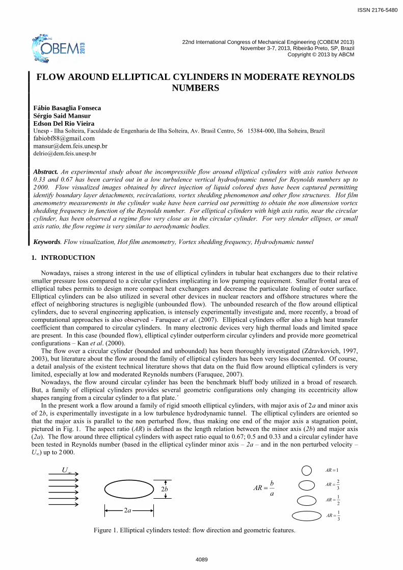
In the present work a flow around a family of rigid smooth elliptical cylinders, with major axis of 2a and minor axis of 2b, is experimentally investigate in a low turbulence hydrodynamic tunnel. The elliptical cylinders are oriented so that the major axis is parallel to the non perturbed flow, thus making one end of the major axis a stagnation point, pictured in Fig. 1. The aspect ratio (AR) is defined as the length relation between the minor axis (2b) and major axis (2a). The flow around three elliptical cylinders with aspect ratio equal to 0.67; 0.5 and 0.33 and a circular cylinder have been tested in Reynolds number (based in the elliptical cylinder minor axis – 2a – and in the non perturbed velocity – U∞) up to 2 000.
Figure 1. Elliptical cylinders tested: flow direction and geometric features.
a2
b2 abAR 3
2AR
1AR
21
AR
31
AR
U
ISSN 2176-5480
4089
F. B. Fonseca, S. S Mansur and E. D. R. Vieira Flow Around Elliptical Cylinders in Moderate Reynolds Number
2. VORTEX SHEDDING FREQUENCY IN ELLIPTICAL CYLINDER WAKE
The bounded flow around an elliptic cylinder (AR = 0.5) inner a turbulent boundary layer is experimentally
investigated using an aerodynamic tunnel and hot-wire anemometry by Choi & Lee, (2001) for Reynolds number, based in the height (2b) of the elliptic cylinder, equals to 1.3×10⁴. In this work, the elliptic cylinder is positioned near a smooth flat plate inner a turbulent boundary layer. The flow structures around elliptic cylinder are strongly influenced by the presence of the flat plate. For an adequate distance between the center of the elliptic cylinder and the wall (almost unbound flow), Strouhal number shows a good agreement with previous experimental studies carried out on uniform flow – far the walls influence – made by Modi & Wiland, (1970) – with 0.6 <AR< 0.8 and 3×10⁴ <Re<1×10⁵ – and Ota et al. (1987) – with AR = 0.33 and 3.5×10⁴ <Re<1.25×10⁵. Previous work of Choi & Lee, (2000) shows same results for elliptic cylinder – AR = 2 – and Reynolds equals to 1.4×10⁴. Although a small variation of the values of the Strouhal number can be observed, they are due, principally, to the differences in the cylinder axes ratio.
Numerical results obtained by Sheard, (2007) – Reynolds numbers up to 500 – and Mittal & Balachandar, (1996) – Reynolds equals to 525 and 1000 –, both using two-dimensional Direct Numerical Simulation with elliptic cylinders of AR = 0.5, show a relative good agreements for Strouhal number with experimental results obtained in hydrodynamic tunnel by Vieira et al. (1997) in the same Reynolds range but AR = 0.6. Experimental results for elliptic cylinder obtained in aerodynamic tunnel are restricted to relative high Reynolds numbers – more than 1 ×10⁴, because small velocity flows produced by aerodynamic tunnel are very unstable since air density is very small than compared with the density of liquids. In this situation, with very small density and low velocities, small inertia is observed and a very small perturbation can produces undesirable strong effects in the flow profile. But, for hydrodynamic flows, the high value of water density produces relative high values of kinetics energy generating stable flows in very small water velocities. For Reynolds less than 1 ×10⁴, hydrodynamic tunnels can produce very stable flows with stable profiles and show adequate for experiments in this Reynolds range.
In accord to Raman et al. (2010), the Immersed Boundary Numerical Method finds promising for to simulate a class of flow problems such elliptic cylinders with less computational cost. Raman et al. (2010) show simulate 2D flows past unconfined elliptic cylinders with 0.1 <AR <1.0 and 50 < Re < 100. For circular cylinder (i.e. AR = 1) the value of critical Reynolds number when the vortices begin to shed is around 47 in agreement with the reviews of Sumer & Fredsoe, (2006) and Zdravkovich, (1997, 2003). The Reynolds value above which onset of vortex shedding occurs is termed as critical Reynolds number (Rec). Obviously, critical Reynolds numbers depend of AR values. If AR decreases the vortex shedding frequency tends to decrease. If Rec is less than critical value, only a stable double vortex loop is formed behind the cylinder. Second Raman et al. (2010), the Rec can be identified in numerical works using the time history of the coefficient of lift or drag. If vortex shedding occurs the drag and lift coefficient show a periodic variation. Raman et al. (2010) identified Rec = 50 to AR = 0.9 and Rec = 100 to AR = 0.6. These authors are ensured that is no vortex shedding for AR < 0.6.
Johnson et al. (2004) use direct numerical simulation in order to simulate 2D elliptical cylinders with AR >1.0 and 75 < Re < 175. The power spectrum analysis of the vertical velocity along the horizontal centerline is utilized in order to determine the vortex shedding frequency. Results for AR = 1 is in agreement with the technical literature. Other numerical works using 2D Finite-Element analysis made by Jackson (1987) and by Koteswara et al. (2010) show a Rec = 77 and 78, respectively, to AR = 0.5, both to Newtonian fluid. Lattice-Boltzmann 2D numerical approach made by Perumal et al. (2012) shows Rec = 78 for AR = 0.5 with a blockage ratio of 6.25. It is very well known if blockage ratio increases the vortex shedding frequency increases. Unfortunately, all of these numerical works the Reynolds number is limited to less than 175.
In summary, we can conclude that none of these articles provides a detailed study of the vortex shedding frequency with similar geometric characteristics and Reynolds numbers showed in the present work. 3. VORTEX SHEDDING FREQUENCY DETERMINATION
Since the famous Strouhal´s experiment of the eolic harp, several accurate methods for determining the vortex
shedding frequency (f ) have been proposed in technical literature. Vortex-shedding frequency is measured by several means in scientific laboratories. Modi & Dikshit (1975) employed successfully a high sensible pressure transducer positioned at the centerline of the vortex wake and Sarpkaya & Kline (1982) measured the lift force actuating on the body using small pressure sensors. Many researchers prefer to determine a spectral analysis of the flow velocity in a fixed point on the wake. In that cases, the velocity signal are obtained by several ways, hot-wire anemometers – Van Atta (1968), Okajima (1982) and Kawakita & Silvares (1993) – laser Doppler Anemometers – Tokumaru & Dimotakis (1991) and Durão et al. (1991), at last, using particle image velocimetry – Agüi & Jiménez (1997) and Lourenço et al. (1997).
In an industrial environment use of vortex flowmeters in order to determine the volumetric flow need to measure the vortex shedding frequency. Generally, in the vortex shedding flowmeters for industrial applications are made utilizing a magnetic sensor assembled at an end of the bluff-body (shedder). This magnetic sensor captures small bluff-body
ISSN 2176-5480
4090
22nd International Congress of Mechanical Engineering (COBEM 2013) November 3-7, 2013, Ribeirão Preto, SP, Brazil
oscillations due to vortices shedding, Doebelin, (1994). Modern vortex shedding flowmeters also use for vortex detection an ultrasonic transmitter and receiver arrangement. As the vortex passes between the transmitter and receiver the electrical signal on the receiver is interrupted and the frequency of interruptions indicates the vortex shedding frequency - Sasaki et al. (1982). Use of ultrasonic sensors in industrial applications is done because they are immune to noise and vibration in the pipes and they are reliable, Basile, (1995). Unfortunately, the vortex shedding frequency in industrial vortexmeters, for maximum flow rate, is of the order of 200 to 500 Hz. In this present work, the main aim is the measure of very small frequency, about 1 Hz. Several difficulties are associated with measures of small vortex frequency mainly due to relative low value of the signal to noise ratio – Bassan et al. (2012).
The determination of the frequency (f ), is possible using a simple method of flow observation, e.g. by means of smoke trails in conjunction with a stroboscope light. Direct injection of smoke tracers, generally produced by a large variety of smokelike materials such as vapors, fumes and mists, usually upstream of the fluid dynamic model, are intensively used for qualitative flow visualization in wind tunnels, see Mueller (1983). According to Ower & Pankhurst (1977) there are no published records of the direct use of such a quantitative method, but it is not true, because Brown (1952), successfully, utilized a smoke tracer produced by burning wheat straw under a slight pressure and insufficient oxygen and a mechanical stroboscope light driven by a synchronous motor to measure the shedding frequency (f ) from a circular cylinder in a low turbulence subsonic wind tunnel.
Generally, the use of non-intrusive method for the determination of quantities relating to the flow fields always found excellent responsiveness in the scientific and industrial applications. The method of counting frames recorded on video tape – Vieira, (1997) – fits into this context, allowing quantification in laboratory applications, some dynamic magnitudes of flows that can be visualized. Vortex shedding can be easily visualized using several different flow visualization techniques. A video image recorded permits to identify the time between two consecutive vortices. Use of flow visualization in order to determine the vortex shedding frequency is used only if very small frequencies are observed. If the vortices are shedding in relative high frequency, the use of high speed camera is absolutely necessary.
Flow visualization is a useful tool in order to identify larger turbulent flow structures like vortex street wake. Using flow visualization video images is possible to determine the vortex shedding frequency. Unfortunately, video images are conventionally recorded in less than 30 frames per second and only small frequency, less than 6 Hz, can be detected. For more high frequency, use of high speed camera is necessary. 4. EXPERIMENTAL APPARATUS
Figure 2 depicts a sketch of the vertical hydrodynamic tunnel showing the principal parts. An external
subterraneous water tank (LR) with a capacity of 9.8 m3, careful protected against dust and possible contaminants, provides the water for the experiments. The water pump (PP) is a KSB pump model Megachem 32-200 type of 5,5 kW of power all constructed in stainless steel to fit out in a level below of the reservoir level. The pump is installed in a subterraneous power-house, external the laboratory room, careful to fit up on vibration isolated supports in order to minimize the vibration transmission to the tunnel. A 75 mm nominal diameter PVC tube with 5 mm of wall thickness positioned in the exhaust of the pump discharge the flow to the upper of the tunnel. All valves are made in stainless steel except to valve #3. All valves showed in Fig. 2 are of manual operating. Use of valves type sphere or butterfly permits to control the flow rate adequately. The valve #2 is a butterfly valve installed in order to manually control the flow inlet the tunnel. This valve type mounted after the pump in a high pressure line and operated only by one quarter of lap need be slowly moved in order to avoid the sudden flow interruption causing undesirable hydraulic ham effect.
The stagnation section (the upper part of the tunnel) is composed by an upper reservoir (UR), an upper contraction (UC), screens (S), honeycombs (SH) and a discharge diffuser. Discharge diffuser, contraction and screens are needed in order to introduce the flow field with a minimal turbulence in stagnation section. The work of Vogt (1983) discusses the problem due to residual turbulence internal the stagnation section in vertical hydrodynamic tunnel. The honeycombs with hexagonal cells of 6 mm and 280 mm of thickness are made of fine sheet of alloy 3003 aluminum. The discharge diffuser shows 614 small holes of 3 mm of diameter proportionally distributed order to delivery uniformly the flow inside the stagnation section producing a minimal perturbation, principally in continuous mode operation.
The maximum water level internal the upper reservoir in controlled by an exhaust PVC pipe of 100 mm nominal diameter. The contraction (LC) has a short length and a contraction ratio of 1:16. The test section (TS) was made of aeronautical aluminum 4050 with windows of optical Plexiglas with 10 mm of thickness. The average velocity at the test section has been determined from the water flow rate measured by an electromagnetic flowmeter (FM). This practice of determination of the average velocity in the test section measuring the downstream bulk flow rate is used in many water tunnel facilities. The non-perturbed velocity, upstream the test model has been obtained, in this work, using an AXF100G model Yokogawa electromagnetic flow meter mounted downstream the test section. An assessment of the uncertain associated to free stream velocity shown less than 4%, when compared with data obtained by hot film anemometer (Dantec CTA Streamline).
The tunnel structural support was entirely constructed of NPS 6 Schedule 40 steel pipes with 150 mm of nominal diameter and 7 mm of wall thickness for a rigid structure with minimal vibrations. Seamless Schedule pipes provide a high quality tube for structural application. The tunnel structure need be to place careful in an adequate foundation bases in order to isolate external vibration conducted by the ground. The tunnel structural support was entirely constructed of NPS 6 Schedule 40 steel pipes with 150 mm of nominal diameter and 7 mm of wall thickness for a rigid structure with
ISSN 2176-5480
4091
F. B. Fonseca, S. S Mansur and E. D. R. Vieira Flow Around Elliptical Cylinders in Moderate Reynolds Number
minimal vibrations. Seamless Schedule pipes provide a high quality tube for structural application. The tunnel structure need be to place careful in an adequate foundation bases in order to isolate external vibration conducted by the ground.
All parts of tunnel have been made of low water absorption composite material (polyester isophthalic resins and glass fiber) with 8 mm of thickness strengthened with a steel gage in order to provide very strong walls. In a hydrodynamic tunnel, all walls need be sufficiently rigid because small wall oscillations can provoke boundary layer detachment and high level of turbulence. Direct water contact with metallic walls provokes the ions formation generating several chemical reactions in many parts of the tunnel and irreversible damages on expensive hot film probes. In order to minimize the chemical reactions, all the tubes and connections have been made of thermoplastic PVC (Polyvinyl chloride). In order to avoid undesirable vibrations and deformations of the tubes and to support severe operation modes, all tubes present a minimal of 3 mm of wall thickness. All valves and the pump are of stainless steel due to use of carbon steel in water contact generates oxidation and severe water contamination.
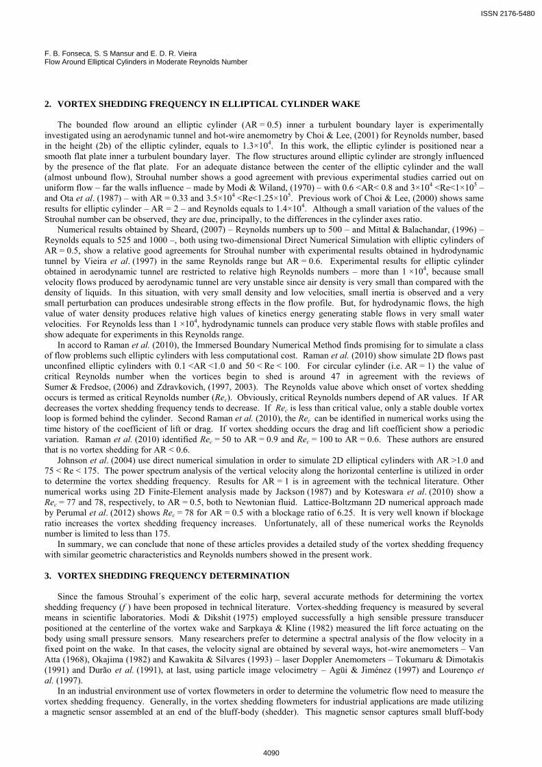
Boundary layer thickness effect on velocity profile is controlled by divergent walls in the test section showing an adequate solution. Low velocity aerodynamic tunnel also utilizes currently divergent walls in test section in order to remain constant the velocity profile. The water tunnel is operated by gravitational action, and can be used in continuous or blow-down mode. Blow-down mode have been used in this work, due to its lower turbulence level, although in this mode, the free stream mean velocity decreases noticeably with the water level inside the upper reservoir. To account for that, it has been estimated that, for a period up to 15 seconds, the effects of decreasing free stream mean velocity are overshadowed by turbulence. Fig. 3 shows the non perturbed free stream temporal velocity (black line), the mean velocity (red line), the temporal velocity fluctuation (green line) and the mean velocity fluctuation (blue line) in the test section where elliptic cylinders are mounted in continuous tunnel operation mode. With the data obtained by hot film anemometry, the calculated turbulent intensity was less than 0.24%, i.e., the tunnel has relatively very small velocity fluctuations enabling the study of turbulent flow, even when operating in steady state. For operation under blow down mode, are expected to significantly lower levels of turbulence due to the decrease in the degree of disturbance.
Figure 2. Vertical hydrodynamic tunnel.
ISSN 2176-5480
4092
22nd International Congress of Mechanical Engineering (COBEM 2013) November 3-7, 2013, Ribeirão Preto, SP, Brazil
0 2 4 6 8 100,0000
0,0005
0,0010
0,0015
0,0020
0,0025
0,0672
0,0675
0,0678
0,0681
0,0684
0,0687
Vel
ocity
[ m
/s ]
time[ s ]
Velocity u Mean velocity u
m
Velocity fluctuation |u'| Mean velocity fluctuation |u'|
m
Figure 3. Free stream velocity and velocity fluctuation in test section.
5. RESULTS
Figure 4 shows the flow around the elliptical cylinder AR = 0.67 tested for Reynolds between 13 and 1 789. For
Re = 13, it can be seen that the flow regime is laminar and the early formation of the closed symmetric vortices in the wake. For Re = 56, the wake is no longer symmetric and notes the start of the oscillatory motion of the emission lines downstream of the cylinder. For flows with Reynolds number greater than or equal to 77, there is the phenomenon of alternating vortices shedding. The transition from the wake may not be so clearly observed, although in some captured images as Re equal to or greater than 600, has the impression that the most downstream vortices become irregular. For Re = 1789, the wake behind the cylinder is without any observable trace of laminar.
The flow patterns around the elliptic cylinder AR = 0.67 are very close to those observed for flow around the circular cylinder. For example, when considering Reynolds values between 107 and 498, it is noted that the vortices approach each other when the Reynolds number is increased, similarly to what occurred circular cylinder. In addition, when comparing other Reynolds numbers it can be seen that the images of the flow patterns around elliptic cylinder are very similar to the flow past circular cylinder. Therefore, with the results showed, no clear difference can be observed between the flow around the circular cylinder and elliptical cylinder with AR = 0.67.
Figure 5 shows the still images of the flow around the elliptic cylinder AR = 0.5 for Reynolds numbers from 28 up to 1 890. Two symmetrical recirculation stable bubbles could be observed for Re = 28, and for Re greater than 72, is possible to observe the shedding of alternating vortices downstream of the cylinder. The results do not show any appreciable difference in the flow patterns around an elliptic cylinder with patterns of flow around a circular cylinder.
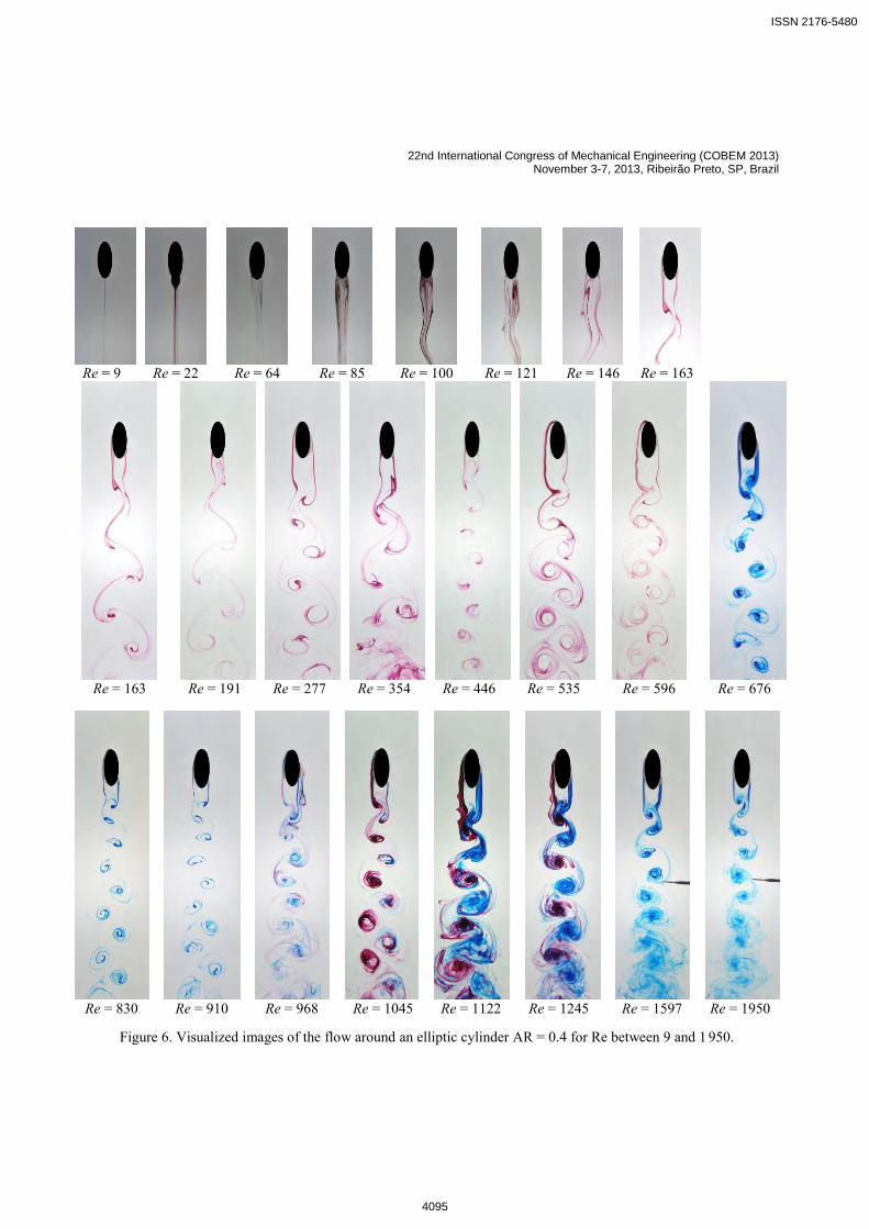
Figure 6 shows images of flow around an elliptic cylinder with AR = 0.4 for the Re number ranging from 9 to 1 950. In Re = 9, it is possible to observe a laminar wake behind the cylinder, which appears to be a case of creeping flow where emission lines remain attached to the surface of the cylinder throughout its perimeter. Two stable symmetrical recirculation bubbles are observed in Re = 22, 64 and 85, and from Re = 100, the wake performs a oscillatory motion until it begins issuing alternating vortices, which is shown in cases where the Reynolds number is less than 163. For Re = 1122 and 1245 it was observed that dye particles emitted from one side of the cylinder interact with vortex opposite evidenced by the different emitted colors of dye on each side of the cylinder. Already in the last pictures, where Re = 1597 and 1950, we note that the vortices begins to lose its identity further downstream of the cylinder at the bottom of the images, being very turbulent. Only to Re = 100 the oscillatory motion of the wake is observed. This may be a first evidence of elliptic cylinders with low AR have aerodynamic characteristics closer to those found in aerodynamic bodies. Figure 7 shows images of flow around an elliptic cylinder with AR = 0.33 for the Re number ranging from 5 to 1 999. As occurred in the other tests is also observed that increasing the Reynolds number decreases the distance between two consecutive vortices. For example, when Re = 311 are found four vortices emitted and a half of a fifth, and another vortex formation, totaling six coherent structures. For Re = 587, there are six vortices issued and another forming a total of seven vortices. Another important observation can be made by comparing the flow regimes around the circular cylinder with the flow around the elliptical cylinder of AR = 0.33. In the case of circular cylinder, it is observed that the wake behind the body performs a oscillatory motion and initiates the formation of alternating vortices for Re more than approximately 40. But, in the case of the elliptical cylinder of AR = 0.33 the wake is still symmetric and has two recirculation bubbles still inside for of Re = 75. This observation supports the fact that an elliptical cylinder thinner, positioned in the flow with the same slope of the tests, has characteristics closer to an aerodynamic body. In this case, the decrease in the ratio of axes of the ellipse instability tends to retard the wake oscillations and consequent emission of alternating vortices.
ISSN 2176-5480
4093
F. B. Fonseca, S. S Mansur and E. D. R. Vieira Flow Around Elliptical Cylinders in Moderate Reynolds Number
Figure 4. Visualized images of the flow around an elliptic cylinder AR = 0.67 to Reynolds between 13 and 1 789.
Figure 5. Visualized images of the flow around an elliptic cylinder AR = 0.5 for Re between 28 and 1890.
22nd International Congress of Mechanical Engineering (COBEM 2013) November 3-7, 2013, Ribeirão Preto, SP, Brazil
Re = 9 Re = 22 Re = 64 Re = 85 Re = 100 Re = 121 Re = 146 Re = 163
Re = 163 Re = 191 Re = 277 Re = 354 Re = 446 Re = 535 Re = 596 Re = 676
Re = 830 Re = 910 Re = 968 Re = 1045 Re = 1122 Re = 1245 Re = 1597 Re = 1950
Figure 6. Visualized images of the flow around an elliptic cylinder AR = 0.4 for Re between 9 and 1 950.
ISSN 2176-5480
4095
F. B. Fonseca, S. S Mansur and E. D. R. Vieira Flow Around Elliptical Cylinders in Moderate Reynolds Number
Re = 132 Re = 145 Re = 192 Re = 213 Re = 245 Re = 275 Re = 292
Re = 311 Re = 330 Re = 374 Re = 455 Re = 521 Re = 587
Re = 676 Re = 800 Re = 844 Re = 872 Re = 923 Re = 1015
Re = 1083 Re = 1188 Re = 1305 Re = 1413 Re = 1774 Re = 1999
Figure 7. Visualized images of the flow around an elliptic cylinder AR = 0.33 for Re between 5 and 1 999.
ISSN 2176-5480
4096
22nd International Congress of Mechanical Engineering (COBEM 2013) November 3-7, 2013, Ribeirão Preto, SP, Brazil
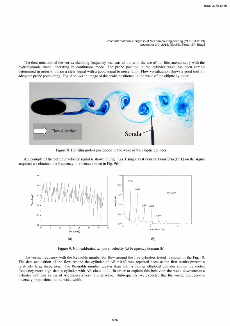
The determination of the vortex shedding frequency was carried out with the use of hot film anemometry with the
hydrodynamic tunnel operating in continuous mode. The probe position in the cylinder wake has been careful determined in order to obtain a clear signal with a good signal to noise ratio. Flow visualization shows a good tool for adequate probe positioning. Fig. 8 shows an image of the probe positioned in the wake of the elliptic cylinder.
Figure 8. Hot film probes positioned in the wake of the elliptic cylinder.
An example of the periodic velocity signal is shown in Fig. 9(a). Using a Fast Fourier Transform (FFT) on the signal acquired we obtained the frequency of vortices shown in Fig. 9(b).
0 5 10 15 20 25 30 353,0
3,1
3,2
3,3
3,4
3,5
Tens
ão (V
)
Tempo (s) 0 2 4
0,00
0,01
0,02
0,03
0,04
0,05
Frequência (Hz)
Am
plitu
de
0,519
1,038
1,587 2,106
2,624
Re = 227
(a) (b)
Figure 9. Non calibrated temporal velocity (a) Frequency domain (b).
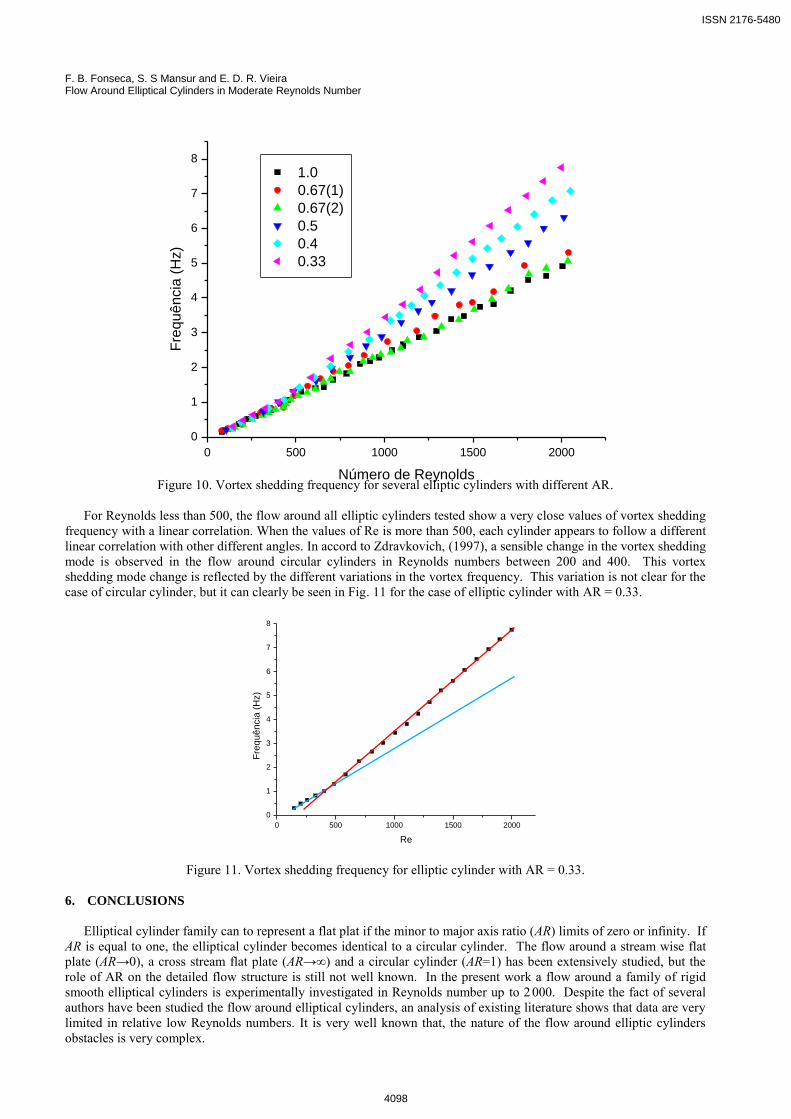
The vortex frequency with the Reynolds number for flow around the five cylinders tested is shown in the Fig. 10. The data acquisition of the flow around the cylinder of AR = 0.67 was repeated because the first results present a relatively large dispersion. For Reynolds number greater than 500, a thinner elliptical cylinder shows the vortex frequency more high than a cylinder with AR close to 1. In order to explain this behavior, the wake downstream a cylinder with low values of AR shows a very thinner wake. Subsequently, we expected that the vortex frequency is inversely proportional to the wake width.
Flow direction
ISSN 2176-5480
4097
F. B. Fonseca, S. S Mansur and E. D. R. Vieira Flow Around Elliptical Cylinders in Moderate Reynolds Number
0 500 1000 1500 20000
1
2
3
4
5
6
7
8Fr
equê
ncia
(Hz)
Número de Reynolds
1.0 0.67(1) 0.67(2) 0.5 0.4 0.33
Figure 10. Vortex shedding frequency for several elliptic cylinders with different AR.
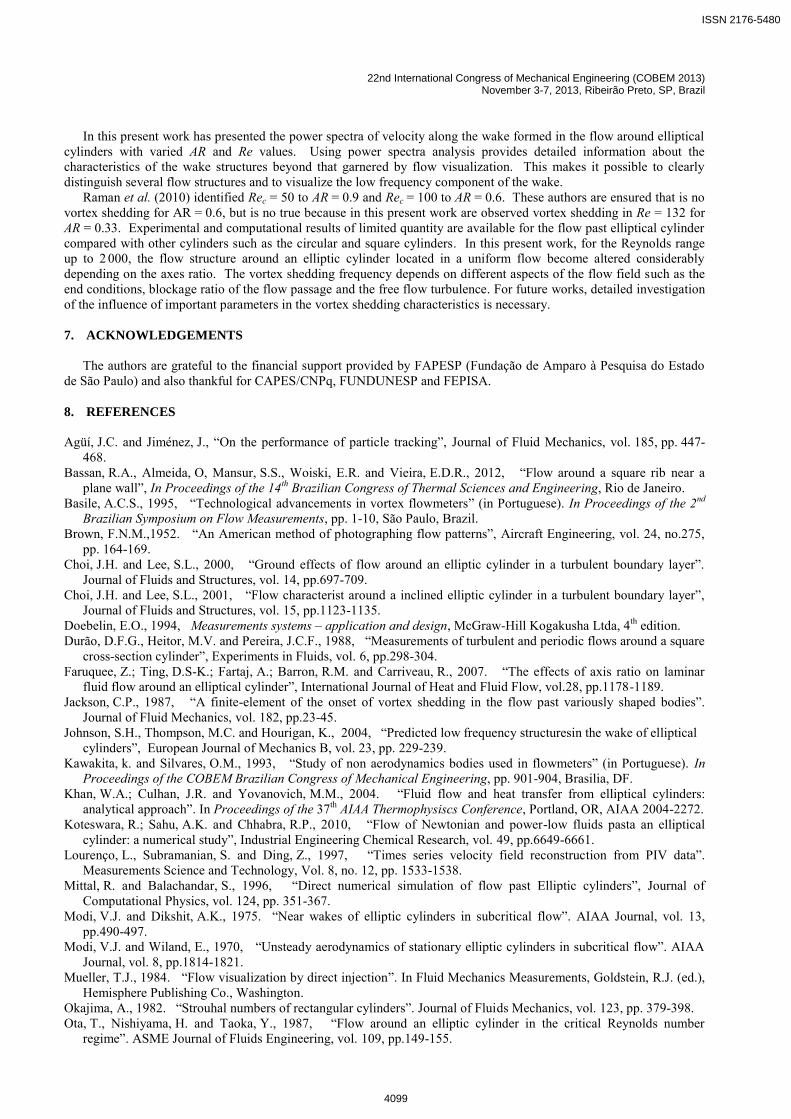
For Reynolds less than 500, the flow around all elliptic cylinders tested show a very close values of vortex shedding frequency with a linear correlation. When the values of Re is more than 500, each cylinder appears to follow a different linear correlation with other different angles. In accord to Zdravkovich, (1997), a sensible change in the vortex shedding mode is observed in the flow around circular cylinders in Reynolds numbers between 200 and 400. This vortex shedding mode change is reflected by the different variations in the vortex frequency. This variation is not clear for the case of circular cylinder, but it can clearly be seen in Fig. 11 for the case of elliptic cylinder with AR = 0.33.
0 500 1000 1500 20000
1
2
3
4
5
6
7
8
Freq
uênc
ia (H
z)
Re
Figure 11. Vortex shedding frequency for elliptic cylinder with AR = 0.33. 6. CONCLUSIONS
Elliptical cylinder family can to represent a flat plat if the minor to major axis ratio (AR) limits of zero or infinity. If
AR is equal to one, the elliptical cylinder becomes identical to a circular cylinder. The flow around a stream wise flat plate (AR→0), a cross stream flat plate (AR→∞) and a circular cylinder (AR=1) has been extensively studied, but the role of AR on the detailed flow structure is still not well known. In the present work a flow around a family of rigid smooth elliptical cylinders is experimentally investigated in Reynolds number up to 2 000. Despite the fact of several authors have been studied the flow around elliptical cylinders, an analysis of existing literature shows that data are very limited in relative low Reynolds numbers. It is very well known that, the nature of the flow around elliptic cylinders obstacles is very complex.
ISSN 2176-5480
4098
22nd International Congress of Mechanical Engineering (COBEM 2013) November 3-7, 2013, Ribeirão Preto, SP, Brazil
In this present work has presented the power spectra of velocity along the wake formed in the flow around elliptical cylinders with varied AR and Re values. Using power spectra analysis provides detailed information about the characteristics of the wake structures beyond that garnered by flow visualization. This makes it possible to clearly distinguish several flow structures and to visualize the low frequency component of the wake.
Raman et al. (2010) identified Rec = 50 to AR = 0.9 and Rec = 100 to AR = 0.6. These authors are ensured that is no vortex shedding for AR = 0.6, but is no true because in this present work are observed vortex shedding in Re = 132 for AR = 0.33. Experimental and computational results of limited quantity are available for the flow past elliptical cylinder compared with other cylinders such as the circular and square cylinders. In this present work, for the Reynolds range up to 2 000, the flow structure around an elliptic cylinder located in a uniform flow become altered considerably depending on the axes ratio. The vortex shedding frequency depends on different aspects of the flow field such as the end conditions, blockage ratio of the flow passage and the free flow turbulence. For future works, detailed investigation of the influence of important parameters in the vortex shedding characteristics is necessary. 7. ACKNOWLEDGEMENTS
The authors are grateful to the financial support provided by FAPESP (Fundação de Amparo à Pesquisa do Estado
de São Paulo) and also thankful for CAPES/CNPq, FUNDUNESP and FEPISA. 8. REFERENCES
Agüí, J.C. and Jiménez, J., “On the performance of particle tracking”, Journal of Fluid Mechanics, vol. 185, pp. 447-
468. Bassan, R.A., Almeida, O, Mansur, S.S., Woiski, E.R. and Vieira, E.D.R., 2012, “Flow around a square rib near a
plane wall”, In Proceedings of the 14th Brazilian Congress of Thermal Sciences and Engineering, Rio de Janeiro. Basile, A.C.S., 1995, “Technological advancements in vortex flowmeters” (in Portuguese). In Proceedings of the 2nd
Brazilian Symposium on Flow Measurements, pp. 1-10, São Paulo, Brazil. Brown, F.N.M.,1952. “An American method of photographing flow patterns”, Aircraft Engineering, vol. 24, no.275,
pp. 164-169. Choi, J.H. and Lee, S.L., 2000, “Ground effects of flow around an elliptic cylinder in a turbulent boundary layer”.
Journal of Fluids and Structures, vol. 14, pp.697-709. Choi, J.H. and Lee, S.L., 2001, “Flow characterist around a inclined elliptic cylinder in a turbulent boundary layer”,
Journal of Fluids and Structures, vol. 15, pp.1123-1135. Doebelin, E.O., 1994, Measurements systems – application and design, McGraw-Hill Kogakusha Ltda, 4th edition. Durão, D.F.G., Heitor, M.V. and Pereira, J.C.F., 1988, “Measurements of turbulent and periodic flows around a square
cross-section cylinder”, Experiments in Fluids, vol. 6, pp.298-304. Faruquee, Z.; Ting, D.S-K.; Fartaj, A.; Barron, R.M. and Carriveau, R., 2007. “The effects of axis ratio on laminar
fluid flow around an elliptical cylinder”, International Journal of Heat and Fluid Flow, vol.28, pp.1178-1189. Jackson, C.P., 1987, “A finite-element of the onset of vortex shedding in the flow past variously shaped bodies”.
Journal of Fluid Mechanics, vol. 182, pp.23-45. Johnson, S.H., Thompson, M.C. and Hourigan, K., 2004, “Predicted low frequency structuresin the wake of elliptical
cylinders”, European Journal of Mechanics B, vol. 23, pp. 229-239. Kawakita, k. and Silvares, O.M., 1993, “Study of non aerodynamics bodies used in flowmeters” (in Portuguese). In
Proceedings of the COBEM Brazilian Congress of Mechanical Engineering, pp. 901-904, Brasilia, DF. Khan, W.A.; Culhan, J.R. and Yovanovich, M.M., 2004. “Fluid flow and heat transfer from elliptical cylinders:
analytical approach”. In Proceedings of the 37th AIAA Thermophysiscs Conference, Portland, OR, AIAA 2004-2272. Koteswara, R.; Sahu, A.K. and Chhabra, R.P., 2010, “Flow of Newtonian and power-low fluids pasta an elliptical
cylinder: a numerical study”, Industrial Engineering Chemical Research, vol. 49, pp.6649-6661. Lourenço, L., Subramanian, S. and Ding, Z., 1997, “Times series velocity field reconstruction from PIV data”.
Measurements Science and Technology, Vol. 8, no. 12, pp. 1533-1538. Mittal, R. and Balachandar, S., 1996, “Direct numerical simulation of flow past Elliptic cylinders”, Journal of
Computational Physics, vol. 124, pp. 351-367. Modi, V.J. and Dikshit, A.K., 1975. “Near wakes of elliptic cylinders in subcritical flow”. AIAA Journal, vol. 13,
pp.490-497. Modi, V.J. and Wiland, E., 1970, “Unsteady aerodynamics of stationary elliptic cylinders in subcritical flow”. AIAA
Journal, vol. 8, pp.1814-1821. Mueller, T.J., 1984. “Flow visualization by direct injection”. In Fluid Mechanics Measurements, Goldstein, R.J. (ed.),
Hemisphere Publishing Co., Washington. Okajima, A., 1982. “Strouhal numbers of rectangular cylinders”. Journal of Fluids Mechanics, vol. 123, pp. 379-398. Ota, T., Nishiyama, H. and Taoka, Y., 1987, “Flow around an elliptic cylinder in the critical Reynolds number
regime”. ASME Journal of Fluids Engineering, vol. 109, pp.149-155.
ISSN 2176-5480
4099
F. B. Fonseca, S. S Mansur and E. D. R. Vieira Flow Around Elliptical Cylinders in Moderate Reynolds Number
Ower, E. & Pankhurst, R.C., 1977, “The measurement of air flow”. Pergamon Press, Oxford. Perumal, D.A., Kumar, G.V.S. and Dass, A.K., 2012, “Lattice Boltzmann simulation of viscous flow past elliptical
cylinder”, CFD Letters, vol. 4, no. 3, pp. 127-131. Raman, S.K., Prakash, K.A. and Vengadesan, S., 2010, “Effects of axis ratio on fluid flow around an elliptic cylinder
using immersed boundary method”, In: Proceedings of the 37th National & 4th International Conference on Fluid Mechanics and Fluid Power, Madras, India.
Sarpkaya, T. & Kline, H.K., 1982. “Impulsively-started flow about four types of bluff body”. Journal of Fluids Engeneering, vol. 104, pp. 207-213.
Sasaki, T., Asayama, Y., Motoyoshi, Y., Yamamoto, H. And Fukami, T., 1982. “A Kármán vortex air flow sensor”, SAE Paper 820322.
Sheard, G.J., 2007, “Cylinders with elliptic cross-section: wake stability with variation in angle of incidence”, In: Proceedings of the IUTAM Symposium on Unsteady Separated flows and Their Control, Corfu Island.
Sumer, B.M. and Fredsoe, J., 2006, “Hydrodynamics around cylindrical structures” Advanced Series in Ocean Engineering, vol. 26, Technical University of Denmark, 548 p.
Tokumaru, P.T. and Dimotakis, P.E., 1991, “Rotary Oscillation Control of a Cylinder Wake”, Journal of Fluid Mechanics, vol. 224, pp.77-90.
Van Atta, C.W., 1968. “Experiments on vortex shedding from yawed circular cylinders”. AIAA Journal, vol. 6, pp. 931-933.
Vieira, E.D.R., 1997, “Qualitative and quantitative study of the flow around non-aerodynamics bodies utilizing flow visualization techniques in hydrodynamic medium” (in Portuguese). Thesis, ITA, São José dos Campos, Brazil.
Vieira, E.D.R., Duarte, J., Mansur, S.S. and Zaparoli, E.L., 1997, “Experimental determination of vortex shedding frequency of elliptical cylinder”. In Procedings of the IV Latin American Meeting in Fluid Dynamic, Itajubá, Brazil.
Vogt G.L., 1983, “Water tunnel construction for continuous mode flow visualization”. In Proceedings of the AIAA 21th Aerospace Sciences Meeting, AIAA – 830657, Reno, Nevada, USA.