Received: February 2018, Accepted: April 2018 Correspondence to: Davood Khoeini Department of Mechanical Engineering, Isfahan University of Technology, Iran E-mail: [email protected] doi:10.5937/fmet1804463K
Davood Khoeini Department of Mechanical Engineering,
Isfahan University of Technology, Isfahan 84156-83111
Iran
Mohammad Reza Tavakoli Department of Mechanical Engineering,
Isfahan University of Technology, Isfahan 84156-83111
Iran
Flow Characteristics of a Centrifugal Pump with Different Impeller Trimming Methods Influences of different impeller trimming methods on flow characteristics of a centrifugal pump have been studied numerically and experimentally in this research. Different cases of trimmed impellers include straight trimmed impeller with and without remained shrouds, oblique trimmed impeller, triangular trimmed impeller, semi-circular trimmed impeller and polygon-shaped trimmed impeller. Verification of computational results has been investigated through comparison of experimental and numerical data as maximum deviation of 5.4 per cent has been observed. Results revealed that impeller trimming method has profound impact on the centrifugal pump performance as the highest head value has been achieved by employing the impeller with polygon-shaped trimmed shrouds at all flow rates, which is by 5 per cent higher than that of the conventional trimmed impellers (straight trimmed ones). Furthermore, it is also seen that the efficiency of polygon-shaped trimmed impeller was reduced by 3.6 per cent at BEP (Best Efficiency Point). Keywords: Centrifugal pump, impeller trimming, different methods, flow characteristics, experimental and numerical investigation.
1. INTRODUCTION
Centrifugal pumps are integral for numerous industries, ranging from the energy generation and oil and gas industries to the chemical and food industries. Hence, achieving to the higher centrifugal pump performance by different methods [1-5] even after manufacturing, i.e., impeller trimming has been regarded and researchers have contributed to the study of the impeller cutting methods of centrifugal pumps.
Zhou et al. [6] analysed impeller trimming impacts on the performance of a centrifugal pump. They observed that untrimmed impeller has the highest performance of all at high flow rate, while at low flow rate it has the lowest performance. Effects of impeller trimming on vibration and performance of a double volute centrifugal pump were surveyed by Khalifa [7]. His results demonstrated that by impeller trimming lower pump vibration is resulted as minimum vibration was achieved at the BEP, Best Efficiency Point. Qu and Wang [8] investigated influences of four different trimmed impellers of straight, miscut, triangle and parabolic types on performances of a centrifugal pump. They achieved a bit higher head and efficiency at BEP utilizing parabolic trimmed impeller in comparison to other cases. Performance of a deep-well centrifugal pump with various impeller outlet widths was studied by Weidong et al. [9]. They reported that oversizing impeller outlet width caused poor pump performance and enhanced shaft power. Ling Zhou et al. [10]
conducted their numerical and experimental analyses to evaluate the performance and axial thrust of a centrifugal pump impeller with different rear shroud diameters. By using the appropriate impeller rear shroud diameter, higher pump performance and lower axial thrust were accomplished in their research. Savar et al. [11] presented a research on impeller trimming impacts on the performance of a centrifugal pump employed in desalination plants experimentally. They observed that for result extrapolation of low and high specific speed pumps significant geometry differences between them must be considerably regarded. Different requirements of centrifugal pumps in desalination and power plant processes were given by Nemdili and Hellmann [12]. Singh and Mitchell achieved lower pump energy consumption by impeller trimming [13]. Influences of impeller trimming effecting pump as turbine were regarded by Yang et al. [14]. They carried out a research on different parameters, i.e., wrap angle of blade, inlet wide of impeller and inlet angle of blade that are changed by impeller trimming.
As pointed out, although impeller cutting effects on centrifugal pump performance have been considered in previous studies, methods of trimming the outer dia–meter of impeller have mostly been regarded in the parallel direction to the impeller shaft. Moreover, impacts of different impeller trimming shapes, particularly polygon-shaped trimmed impeller have not been analysed yet. Consequently, effects of six different trimmed impellers on centrifugal pump performance containing straight trimmed impeller with no remained shrouds (STI), straight trimmed impeller with remained shrouds (STIS), oblique trimmed impeller (OTI), triangular trimmed impeller (TTI), semi-circular trimmed impeller (SCTI) and polygon-shaped trimmed
464 ▪ VOL. 46, No 4, 2018 FME Transactions
impeller (PTI) have been investigated numerically and validated experimentally in the present research.
2. MAIN REGIONS OF CENTRIFUGAL PUMP
Figure 1 depicts different regions of inlet, impeller and volute casing of the centrifugal pump which have been considered simultaneously in all computations. Besides, all geometry parameters of the centrifugal pump comprising diameters of suction and discharge pipes, diameter of impeller, impeller blades number, leading and trailing blades angles, thickness and height of blades are presented in Table. 1.
Fig. 1 Centrifugal pump parts [1]
Table 1 Centrifugal pump specifications.
Impeller diameter (Untrimmed)
585 mm
Impeller diameter (Trimmed)
550 mm
Inlet blade angle 19° Outlet blade angle 27° Number of blades 4 Blade height 38 mm
Impeller
Blade thickness 8 mm Suction pipe diameter 200 mm Volute Discharge pipe diameter 200 mm
3. EXPERIMENTAL TEST SETUP
In Fig. 2 schematic view of the test apparatus is illustrated. Actually, in this study, performance of the surveyed centrifugal pump is experimentally tested by using water at 25oC [15].
Required power of the mentioned pump was supplied by an AC driver, 1475 rpm. All performance curves (differential head versus flow rate and overall efficiency versus flow rate) in various capacities were obtained according to the [15, 16] by making changes of the discharge globe valve (200 mm) and utilizing an electromagnetic flowmeter (DN 200) with a precision of ±0.5% that were installed at the discharge and suction pipes, respectively. Two bourdon tube type pressure gages with a precision of ±0.1% have been employed for measuring inlet and outlet pressure values at each flow rate as well. 4. GEOMETRY Fig. 3 shows schematic view of all trimmed impellers. In this figure, all trimmed impellers with identical mean trimmed diameter at exit, 550 mm, including STI (Fig. 3 (a) and (b)), OTI (Fig. 3 (c)), TTI (Fig. 3 (d)), SCTI (Fig. 3 (e)) and PTI (Fig. 3 (f)) are presented. Indeed, all parameters of impellers remained the same but the shape of shrouds and/or outlet shape of blades as demonstrated in Fig. 3. Each impeller has been analysed separately and finally experiments were performed.
(a) and (b)
(c)
(d)
(e)
(f)
Fig. 3 Schematic view of different trimmed impellers a) and b) Straight trimmed impeller with remained shrouds (STIS) and without remained shrouds (STI) c) Oblique trimmed impeller (OTI) d) Triangular trimmed impeller (TTI) e) Semi-circular trimmed impeller (SCTI) f) Front and isometric views of polygon-shaped trimmed impeller (PTI)
According to Fig. 3, the outlet edge of original impeller were manipulated by CAD and each surveyed cases of straight trimmed impeller without remained
FME Transactions VOL. 46, No 4, 2018 ▪ 465
shrouds (STI), straight trimmed impeller with remained shrouds (STIS), oblique trimmed impeller (OTI), triangular trimmed impeller (TTI), semi-circular trim–med impeller(SCTI), polygon-shaped trimmed impeller (PTI) were obtained and then, they were analysed numerically and for verification the original impeller was trimmed by milling machine according to the geometry of computational outcome of that case and tested thoroughly. It should be mentioned that all cases own the same blade outlet shape but (OTI), (TTI) and (SCTI) which in these cases some negligible parts of blades outlet have been cut obliquely, triangularly and circularly, respectively as illustrated in Fig. 3.
5. COMPUTATIONAL STUDY
Steady state computations have been conducted with the three- dimensional incompressible Navier- Stocks equations [17]:
0∇ =U (1)
.( ) .( )pρ τ ρ∇ = −∇ +∇ + +UU g F (2)
where the fluid density, velocity and pressure are given by ρ, U and p, respectively and τ and F are the stress tensor and source term as well. For discretization of diffusion and convective terms central difference and high resolution methods have been considered, respectively. Besides, SST turbulence model has been employed in all computations. Furthermore, for inlet boundary condition, total pressure and for outlet boundary condition, mass flow rate and no slip boundary condition for all walls have been regarded for the numerical analyses. 6. MESH GENERATION AND GRID STUDY In Table 2 computational grid investigation has been given. In all cases, hybrid grid has been utilized in all computation domains. Actually, structured grid in the vicinity of the walls and unstructured mesh in other regions has been considered, respectively. The optimum number of cells has been surveyed by different itera–tions in order to ensure mesh independence, see Table. 2. Eventually, the last investigated case, 1967*1000 cells, has been chosen because of the minimum achieved error. Table 2 Grid study
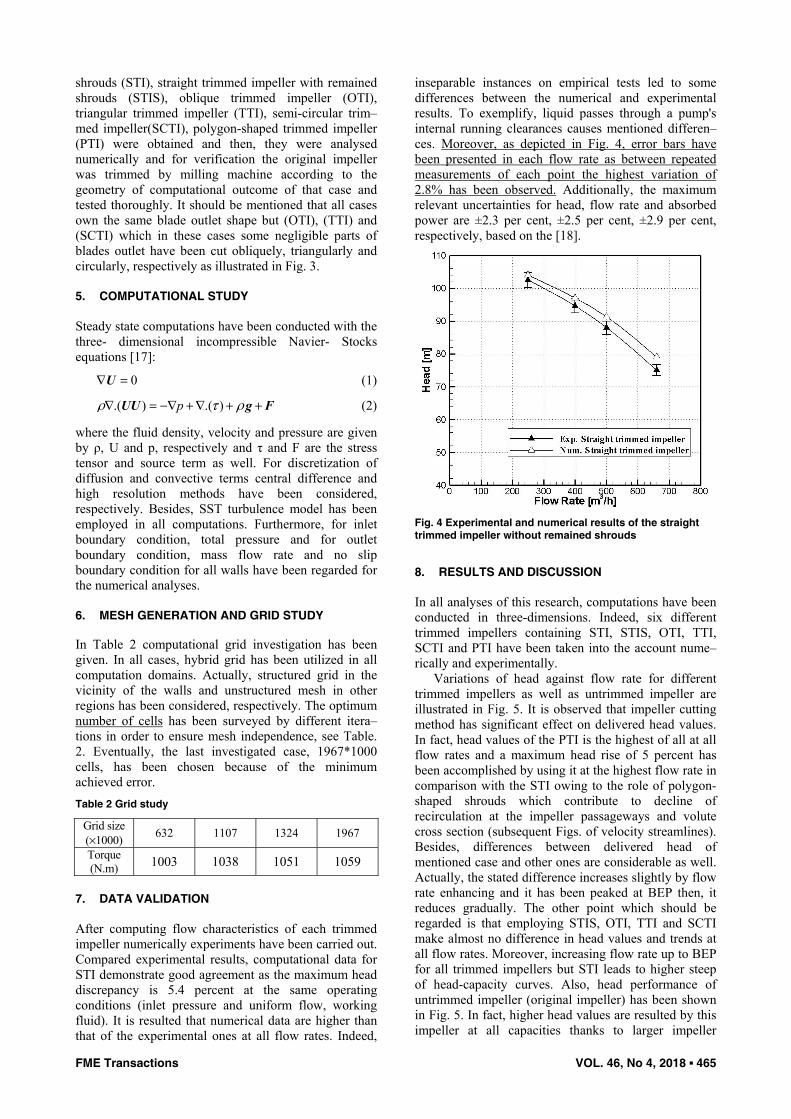
After computing flow characteristics of each trimmed impeller numerically experiments have been carried out. Compared experimental results, computational data for STI demonstrate good agreement as the maximum head discrepancy is 5.4 percent at the same operating conditions (inlet pressure and uniform flow, working fluid). It is resulted that numerical data are higher than that of the experimental ones at all flow rates. Indeed,
inseparable instances on empirical tests led to some differences between the numerical and experimental results. To exemplify, liquid passes through a pump's internal running clearances causes mentioned differen–ces. Moreover, as depicted in Fig. 4, error bars have been presented in each flow rate as between repeated measurements of each point the highest variation of 2.8% has been observed. Additionally, the maximum relevant uncertainties for head, flow rate and absorbed power are ±2.3 per cent, ±2.5 per cent, ±2.9 per cent, respectively, based on the [18].
Fig. 4 Experimental and numerical results of the straight trimmed impeller without remained shrouds
8. RESULTS AND DISCUSSION
In all analyses of this research, computations have been conducted in three-dimensions. Indeed, six different trimmed impellers containing STI, STIS, OTI, TTI, SCTI and PTI have been taken into the account nume–rically and experimentally.
Variations of head against flow rate for different trimmed impellers as well as untrimmed impeller are illustrated in Fig. 5. It is observed that impeller cutting method has significant effect on delivered head values. In fact, head values of the PTI is the highest of all at all flow rates and a maximum head rise of 5 percent has been accomplished by using it at the highest flow rate in comparison with the STI owing to the role of polygon-shaped shrouds which contribute to decline of recirculation at the impeller passageways and volute cross section (subsequent Figs. of velocity streamlines). Besides, differences between delivered head of mentioned case and other ones are considerable as well. Actually, the stated difference increases slightly by flow rate enhancing and it has been peaked at BEP then, it reduces gradually. The other point which should be regarded is that employing STIS, OTI, TTI and SCTI make almost no difference in head values and trends at all flow rates. Moreover, increasing flow rate up to BEP for all trimmed impellers but STI leads to higher steep of head-capacity curves. Also, head performance of untrimmed impeller (original impeller) has been shown in Fig. 5. In fact, higher head values are resulted by this impeller at all capacities thanks to larger impeller
466 ▪ VOL. 46, No 4, 2018 FME Transactions
diameter due to transferring more energy to outgoing flow through impeller passageways. Additionally, reduced gap between untrimmed impeller exit and volute casing provided smoother head curve rather than trimmed ones.
Fig. 6 indicates overall efficiency values of each impeller at different flow rates. Based on Fig. 6, amongst trimmed impellers, the highest efficiency has been accomplished at BEP of STI that is by 3.6 percent higher than that of the corresponding point of PTI. Likewise, at high flow rate, there is higher efficiency values in the case of equipped centrifugal pump with STI compared to other trimmed impellers. The effi–ciency reduction of PTI can be attributed to the increased losses due to higher gap between the varied impeller circumference and volute casing which negati–vely influences efficiency performance. Moreover, with the use of this impeller (PTI) the efficiency curve drops more compared to other impellers. Results also demonstrate that by increasing flow rate efficiency differences between different trimmed impellers decline. As it is depicted in the Fig. 6, TTI owns the highest efficiency at low flow rate followed by SCTI while the PTI shows the lowest efficiency in this case. Besides, the BEP position of all cases are identical but PTI that shifted slightly towards the high flow rate. Furthermore, untrimmed impeller and STI illustrate almost similar efficiency figures at all capacities but high flow rates that higher efficiency values have been resulted for untrimmed impeller. Also, untrimmed impeller provides a BEP displacement of 5.6 percent towards high flow rate.
Fig. 5 Variation of head with flow rate
Pressure distributions of all cases are shown in Fig. 8 at the mid- span plane of the impellers (Fig. 7). Based on Fig. 8, there are lower pressure gradients in the case of STI (Fig. 8 (a)). In other words, the stated impeller could decline pressure difference at impeller passage–ways that caused lower delivered head values in comparison with other trimmed impellers. Amongst all trimmed impellers, the PTI owns the highest pressure gradient of all hence, the highest head values are resulted by using it (Fig. 8 (f)). Likewise, the most heterogeneous pressure field is caused using PTI due to varied outlet edge. Furthermore, on the splitter leading edge of the volute of PTI (Fig. 8 (f)) the pressure gradient is enhanced the most which seems that further
investigations are needed considering the effects of polygon-shaped impellers in future research. Besides, at the tongue of volute of all figures, a pressure drop is observed which is minimized in the centrifugal pumps equipped with OTI as well as PTI. Indeed, unlike other cases, there are more space between circumference of the mentioned impellers and volute tongue for outgoing flow from impeller that results in reduction of pressure drop in this region.
Fig. 6 Variation of overall efficiency with flow rate
Fig. 7 Impeller mid-span plane
(a)
(b)
(c)
(d)
(e)
(f)
Fig. 8 Pressure distribution (a) STI (b) STIS (c) OTI (d) TTI (e) SCTI (f) PTI
FME Transactions VOL. 46, No 4, 2018 ▪ 467
In Fig. 9 the velocity streamlines of different impellers are indicated. In all impellers some re- circulation are seen on the pressure side of the impeller blades and it is because of the difference between the flow angles and impeller blade angles. Additionally, higher velocity gradients are observed in the proximity of the impeller with polygon-shaped shrouds. The shrouds of PTI cause stronger interaction between impeller outlet and volute casing due to the varied peripheral edge of the mentioned impeller. Consequently, the flow losses rise negatively affects the efficiency of this impeller as demonstrated in Fig. 6. Another point is that STI and TTI show more uniform flow field rather than others as higher efficiency performance are accomplished by employing the two mentioned impellers (Fig. 6). Moreover, some vortexes are resulted in the gap of impellers and pump’s volute tongue. Indeed, as stated, limitation between the tongue of volute and impeller leads to some wakes in the vicinity of the volute tongue but their impacts are negligible.
TTI (e) SCTI (f) PTI Fig. 10 depicts velocity streamlines of different
cases at volute cross section at BEP. It is seen that secondary flows vary in each case. Indeed, the mentioned phenomenon in trimmed impellers of STI
(Fig. 10 (a)) and OTI (Fig. 10 (c)) are asymmetry while, other cases of STIS (Fig. 10 (b)), TTI (Fig. 10 (d)) and SCTI (Fig. 10 (e)) show symmetry secondary flows thanks to the remained shrouds which conduct flow. This almost explains why the head and efficiency performances differ from one type of trimmed impeller to other one. Furthermore, the impeller outlet shapes of STIS, TTI and SCTI increase the strength of secondary flows that are presented in Figs. 10 (b) and (d) and (e), respectively. Unlike above pointed out impellers, straight, oblique and polygon cutting of impeller circumference beneficially influences the flow field. In other words, flow with more uniformity has been obtained by declining secondary flows in STI and OTI. Besides, secondary flows in the case of PTI (Fig. 10 (f)) not only demonstrate irregular forms but also show weaker ones in comparison with other trimmed impellers.
(a) (b)
(c) (d)
(e) (f)
Fig. 10 Velocity streamlines at volute cross section
STI (b) STIS (c) OTI (d) TTI (e) SCTI (f) PTI
9. CONCLUSIONS Different trimmed impellers, straight trimmed
impeller without remained shrouds (STI), straight trimmed impeller with remained shrouds (STIS), oblique trimmed impeller (OTI), triangular trimmed impeller (TTI), semi-circular trimmed impeller (SCTI) and polygon-shaped trimmed impeller (PTI) have been analysed numerically and experimentally. Numerical and experimental results have been compared and showed reasonable compatibility. Data analyses illustrated that impeller trimming method has considerable influence on the centrifugal pump performance. Amongst all surveyed cases, PTI depicted the highest head values at all flow rates as higher pressure gradient have been observed through the PTI’s
468 ▪ VOL. 46, No 4, 2018 FME Transactions
passageways compared to other cases while the stated trimmed impeller showed the lowest efficiency values at all capacities. Also, it is revealed that STI delivered the highest efficiency values at all flow rates but minimum capacity. Besides, the BEP of PTI shifts towards the high flow rate and the drop speed of its efficiency enhances by decreasing flow rate.
It seems that more studies are required considering various impeller trimming methods such as vibration performance, pulsation performance, axial and radial thrusts and other aspects accordingly.
REFERENCES
[1] Khoeini D., Tavakoli M. R., The optimum position of impeller splitter blades of a centrifugal pump equipped with vaned diffuser, FME Transactions, Vol. 46, No. 2, pp. 205-210, 2018.
[2] Khoeini D., Shirani E., Enhancement of a centri-fugal pump performance by simultaneous use of splitter blades and angular impeller diffuser, International Journal of Fluid Machinery and Systems, In press, 2018.
[3] Khoeini D., Riasi A., Shahmoradi A., Effects of Volute Throat Enlargement and Fluid Viscosity on the Performance of an Over Hung Centrifugal Pump, International Journal of Fluid Machinery and Systems, Vol. 10, No. 1, pp. 30-39, 2017.
[4] Shankar V.K, et al.: A comprehensive review on energy efficiency enhancement initiatives in centrifugal pumping system” Appl. Energy, Vol. 181, pp. 495–513, 2016.
[5] Ivanović L. T., Erić M. D., Stojanović B. Ž., Ilić A. B., Determination of Tooth Clearances at Trochoidal Pump, FME Transactions Vol. 39, pp. 117-126, 2011.
[6] Zhou P., , Tang J., Mou J., Zhu B., Effect of impeller trimming on performance, World Pumps Volume, Issue 9, pp. 38–41, 2016.
[7] Khalifa A. E., Performance and Vibration of a Double Volute Centrifugal Pump: Effect of Impeller Trimming, Paper No. IMECE2014-36060, pp. V04AT04A063; doi:10.1115/IMECE2014-36060, ASME, 2016.
[8] Qu X., Wang L., Effects of Impeller Trimming Methods on Performances of Centrifugal Pump, J. Energy Eng. 04016008, 2016.
[9] Weidong S. et al: Numerical Prediction and Performance Experiment in a Deep-well Centrifugal Pump with Different Impeller Outlet Width, CHINESE JOURNAL OF MECHANICAL ENGINEERING, Vol. 26, No. 1, pp. 46-52, 2013.
[10] Zhou L., Shi W., Li W., Agarwal R., Numerical and Experimental Study of Axial Force and Hydraulic Performance in a Deep-Well Centrifugal Pump With Different Impeller Rear Shroud Radius, J. Fluids Eng. Vol. 135 No. 10, Paper No: FE-13-1086; doi: 10.1115/1.4024894, 2013.
[11] Savar M., Kozmar H., Sutlovic I., Improving centrifugal pump efficiency by impeller trimming, Desalination, Vol 249, pp. 654–659, 2009.
[12] Nemdili A., Hellmann D. H., The requirements to successful centrifugal pump application for desali–nation and power plant processes, Desalination, Vol. 126, pp. 199-205, 1999.
[13] Singh G., Mitchell J.W., Energy savings from pump impeller trimming, ASHRAE Journal, Vol 40, No. 4, pp. 60–63, 1998.
[14] Yang S.S., Kong F.Y., Jiang W.M., Qu X.Y., Effects of impeller trimming influencing pump as turbine, Computers & Fluids Volume Vol. 67, pp. 72–78, 2012.
[15] API standard 610 (2004) Centrifugal Pumps for Petroleum, Petrochemical and Natural Gas Industries, 10th ed.
[16] ISO 9906 (1999) Rotodynamic Pumps-Hydraulic Performance Acceptance Tests-Grades 1 and 2, International Standardization Organization, Geneva.
[17] Barn Menter F.R., Two-equation eddy-viscosity turbulence models for engineering applications, AIAA Journal, Vol. 32, No. 8, pp. 1598–1605, 1994.
[18] Moffat, R.J., Contributions to the theory of single-sample uncertainty. ASME Journal of Fluids and Engineering, Vol. 104, pp. 250-260, 1982.
NOMENCLATURE
F Source term
P Pressure
U Velocity
ρ Fluid Density
τ Stress tensor scale
ПРОТОЧНЕ КАРАКТЕРИСТИКЕ ЦЕНТРИФУГАЛНЕ ПУМПЕ КОД ПРИМЕНЕ
РАЗЛИЧИТИХ МЕТОДА КОРИГОВАЊА РАДНОГ КОЛА
Д. Кхоеини, М.Р. Таваколи
Применом нумеричке и експерименталне методе проучаван је утицај различитих начина кориговања пречника радног кола центрифугалне пумпе. Коришћени су следећи случајеви кориговања: по правој линији са и без преостале облоге, по косој линији, полукружно и у облику полигона. Верификација резултата израчунавања извршена је упоређивањем експерименталних и нумеричких података пошто је утврђена девијација од 5,4%. Резултати су показали да метод кориговања пречника радног кола има великог утицаја на учинак пумпе јер је највећа вредност добијена применом методе кориговања у облику полигона са облогом при свим брзинама протока, што је за 5% више у односу на примену конвенциналне методе (по правој линији). Осим тога, утврђено је да је степен искоришћења код коригованог радног кола у облику полигона редукован за 3,6% у оптималној радној тачки.