Flow Characterization and Modeling of Strong Round SyntheticJets in Crossflow
Xi Xia∗ and Kamran Mohseni†
University of Florida, Gainesville, Florida 32611-6250
DOI: 10.2514/1.J054880
This study focuses on the flow field of a round synthetic jet issuing into a crossflow. Six cases are investigated in
which the jet-to-freestream velocity ratios range between 2.8 and 8.3. This corresponds to a medium-to-strong
transverse jet, which is characterized using both two-dimensional hot-wire anemometry and particle image
velocimetry techniques. A self-similar model is developed for the centerline trajectory and velocity of a transverse
synthetic jet. The resulting scaling laws are validated with experimental data. The scaling coefficients are found to be
independent of the synthetic jet strength (characterized by the stroke ratio) for large-velocity-ratio cases, provided
that the jet velocity is calculated based on the momentum flux of the leading vortex ring of the synthetic jet.
Furthermore, the velocity component parallel to the crossflow is enhanced over the crossflow velocity in the near field
and fundamentally different from continuous jets. This can be explained by the induced effect of the asymmetric
vortex rings in the near field, which are a result of the interaction between the crossflow and the synthetic jet.
Nomenclature
Af = far-field trajectory coefficientAn = near-field trajectory coefficientAs = characteristic area of jet cross section, m2
B = cavity depth of the synthetic jet actuator, mmBf = far-field w-velocity coefficientBn = near-field w-velocity coefficientD = cavity diameter of the synthetic jet actuator, mmd = orifice diameter of the synthetic jet actuator, mmf = jet driving frequency, HzL = stroke length, mmΔ _Mx = x-component momentum deficit, N_Mz = z-component momentum flux, N_m = mass flux, kg∕sn = unit vector normal to the jet centerlineRes = Reynolds number at the synthetic jet exitr = jet-to-freestream velocity ratios = unit vector tangential to the jet centerlineU = mean flow velocity, m∕su = x-component velocity, m∕su∞ = crossflow velocity, m∕sw = z-component velocity, m∕swj = effective jet velocity, m∕sx = direction parallel to the crossflowxc = x coordinate of the jet centerline, mmz = direction perpendicular to the crossflowzc = z coordinate of the jet centerline, mmα = angle between themeasured flow and the hot-wire probe
axis, degΔ = peak-to-peak deflection of the piezoelectric membrane,
μmΓ = circulation of a vortex, m2∕sν = dynamic viscosity, �N · s�∕m2
I. Introduction
T HE synthetic jet [1–4] is a unique type of jet as its formation doesnot require an internal flow source. For this reason, it is also
called a zero-net-mass-flux (ZNMF) jet. The mechanism of asynthetic jet resembles the propulsive technique of squids orcephalopods [5,6], which create a net-momentum-flux flow byperiodically taking in fluid from the surroundings and then ejectinghigh-momentum shear layers that roll into vortex rings. It is thevortex-ring formation that fundamentally distinguishes synthetic jetsfrom continuous jets. The formation process for a starting vortex ringhas been studied byMaxworthy [7], Saffman [8], Didden [9], Glezer[10], and Gharib and his colleagues [11–13] among others. Later,research interests have been focused on the basic flow of syntheticjets issued into a quiescent environment. In the near field of asynthetic jet, Smith and Glezer [1] and Smith and Swift [14] havefound that the jet formation and evolution is dictated by anondimensional stroke ratio, which is the reciprocal of the Strouhalnumber. Holman et al. [15] found that the stroke ratio dictates the jetformation criterion. However, the far-field flow seems to depend onboth the stroke ratio and the Reynolds number [14,16,17]. In the farfield, the scaled-mean-velocity and turbulent-intensity profiles of allsynthetic jets can be collapsed onto a single self-similar profile[1,18–20]. Because self-similarity is also an intrinsic feature for thefar field of continuous jets, we recently proposed a unified approach[17] to model the far field of both continuous and synthetic jets.Another striking feature of synthetic jets lies in their enhancedentrainment and mixing compared with continuous jets [14,21,22],which can be modeled by an enhanced effective eddy viscosityassociated with the synthetic jet [19].Because of the absence of any flow sources as well as enhanced
entrainment and mixing, synthetic jets have been widely used in avariety of applications [3,4] such as propulsion and maneuvering[6,23], separation control of boundary layers [24–28], as well as flowcontrol over airfoils [29–34]. Recently, synthetic jets have also beenused as acoustic liners that are activated in the resonant mode todissipate acoustic energy in engine ducts [35]. In many synthetic-jetflow control applications, the actuator operates by issuing a syntheticjet into a background crossflow. This operational principle issupported by the finding that the interaction between a synthetic jetand crossflow could facilitatemomentum transfer between inside andoutside of the boundary layer [36–39], and further change thepressure distribution of external flow [25,30,40,41] or modify thevorticity distribution of the flow field [27,31,42,43]. Therefore,studying the flow field of a synthetic jet in crossflow is necessary inunderstanding the control effect of synthetic jet actuators.Previous experimental [36,43–49] and numerical [42,48,50–54]
investigations of a transverse synthetic jet have focused on the
*Graduate Research Assistant, Department of Mechanical and AerospaceEngineering. Student Member AIAA.
†William P. Bushnell Endowed Chair in Mechanical and AerospaceEngineering Department and Electrical and Computer EngineeringDepartment; [email protected]. Associate Fellow AIAA.
interaction of the jet with the crossflow boundary layer. Thesepublications provide an understanding about the vortex generationand evolution as well as the mean flow features in the near-wallregion. Specifically, as shown in Fig. 1, Yehoshua and Seifert [44]and Jabbal and Zhong [43] have found that the interaction betweenthe crossflow and a vortex ring would modify the vorticitydistribution of the vortex in an asymmetric manner and rotate thevortex ring axis toward the upstream of the crossflow. Themajority ofthese studies generally share two common features: a relatively weakjet strength compared with the crossflow (a jet-to-crossflow velocityratio of approximately 1 or less) and a jet penetration depth that iscomparable to boundary-layer thickness. To this end, the studies ofweak jets are primarily related to the applications of boundary-layercontrol. However, for vehicle propulsion or maneuvering, vortexthrusters could operate in the regime of transverse synthetic jets withmedium-to-large velocity ratios. Among the limited literature on thissubject, previous studies [55–57] have mainly investigated the meanflow field to obtain the penetration and centerline trajectory of strongsynthetic jets (velocity ratio much larger than 1). In an attempt topromote the study of strong synthetic jets in crossflow, this studywilldevelop a similaritymodel for the centerline trajectory and velocity ofa strong synthetic jet in a near-uniform crossflow, which has a thinlaminar boundary layer. The motivation for this model is twofold.One comes from the provenmodels of a transverse continuous jet, forwhich similarity analysis [58,59] has been applied to derive scalinglaws for velocity, scalar concentration, and jet trajectory. The secondoriginates from a series of synthetic-jet studies [19,20,57,60] thatseek self-similarity solutions of synthetic jets based on relevantmodels of continuous jets. Because the far fields of continuous jetsand synthetic jets resemble each other if scaled properly [17], it ispossible to extend the solution for a transverse continuous jet to thecase of a synthetic jet in the current study.Previous experimental studies have applied particle image
velocimetry (PIV) [43,44,46–48,61] and hot-wire anemometry(HWA) [36,44,45,56] for flow-field characterization. The HWA isprimarily used for sampling the mean flow, whereas the PIVenablesinstantaneous velocity measurement to help understand theformation and evolution of the vortical structures. In this study,both two-dimensional (2D) HWA and phase-locked PIV will beapplied for flow-field measurement. However, as discussed here, theaccuracy of the HWAwould decrease as the angle between the probeaxis and the mean velocity of the measured flow increases. Toovercome this difficulty in measuring the 2D flow in the center planeof a transverse synthetic jet, a rotary stage together with an iterativeangle-detection scheme was applied to automatically align the probeaxis with the flow direction for each sampling location.This paper is organized as follows. Section II introduces the
experimental approaches for measuring the 2D jet flow using HWAand PIV. Section III presents the preliminary results of the flow fieldfor different cases of transverse synthetic jets. Section IVprovides theself-similar models for the centerline trajectory and velocity of atransverse synthetic jet, and the model for estimating the effectivesynthetic jet velocity. Section V presents the model validation for theproposed centerline trajectory and velocity relations, as well asphysical analysis and discussions. Our final conclusions are givenin Sec. VI.
II. Experimental Approaches
A. Experimental Setup
To experimentally characterize the flow field of transversesynthetic jets, the background crossflow is created by an engineeringlaboratory design (ELD) wind tunnel at the University of Florida.This is a closed-circuit, low-Reynolds-number wind tunnel, thevelocity of which can be maintained between 1 and 90 m∕s using aPID controller, with an uncertainty within 0.05 m∕s. For presentstudy, the flow temperature is maintained at 20°C. The tunnel housesa 0.61 m × 0.61 m × 2.44 m test section, inside which the necessaryapparatus for generating the synthetic jet and acquiring the flow-fielddata are mounted.The synthetic jet is created from a circular cavity sealed by a
piezoelectric disk on one end, and is connected to the surroundingfluid through a round jet orifice on the other. The diameter (D) anddepth (B) of the cavity are 33.5 and 2 mm, respectively, whereas theorifice has a diameter (d) of 2 mm and a thickness of 1 mm. Asinusoidal voltage is applied on the piezoelectric material to drive theoscillatory motion of the disk and causes the periodic suction andejection behaviors of the actuator. The jet strength can be controlledby adjusting the amplitude and frequency of the driving voltage, andquantified by the nondimensional stroke ratio, L∕d, where the strokelength L is the equivalent length of a hypothetical cylindrical fluidslug coming out of the actuator orifice in each stroke. According toKrishnan andMohseni [19], L � αpΔD2∕d2, where αp is a constantand Δ is the peak-to-peak deflection of the piezoelectric membrane.Here, Δ is measured with a laser nano-sensor (LMI LNS type 4),similar to that used in previous studies [16,19]. The total uncertaintyassociated with the calculation of L∕d is around 10%.As shown in Fig. 2, the synthetic jet actuator is mounted flush to
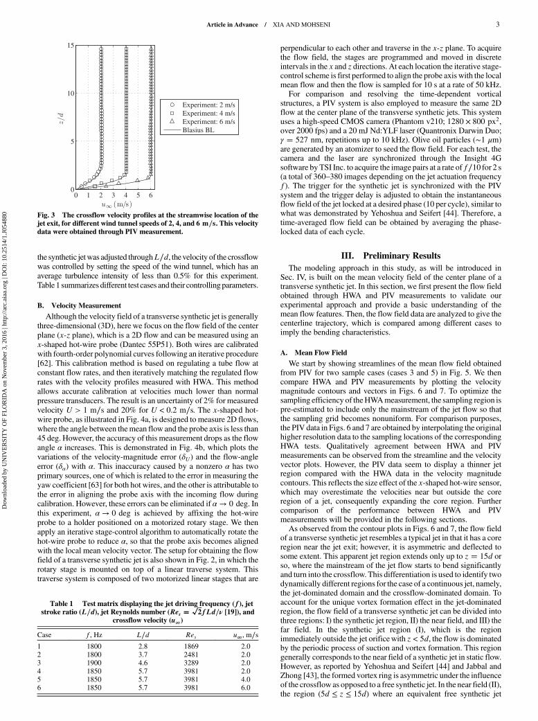
one side of a 30 cm × 20 cm × 0.5 cm acrylic flat plate, which isplaced vertically inside the wind tunnel and parallel to thebackground flow. In this way, the synthetic jet is issued perpendicularto the flow of the wind-tunnel test section, and forms a transversesynthetic jet. The traverse system is mounted on the floor of the windtunnel and the blockage is about 2% of the tunnel cross section. Forclarity, the stage dimensions are exaggerated in Fig. 2. The probesupport creates a vertical distance of 0.3 m between the traversesystem and the flowmeasurement plane, and so the blockage effect isnegligible. As will be discussed in Sec. IV, the transverse jet model inthe current study requires the background flow to be uniform, at leastin the self-similar region of a synthetic jet (starting 10d?15d awayfrom the jet exit). Therefore, it is desirable to have a crossflow with athin laminar boundary layer. For this purpose, the flat plate has beendesigned to have a smooth leading edge (elliptical shape with anaspect ratio of 10) to avoid any disturbances or flow separation. Thisgives a boundary-layer thickness (δ) of less than 3d near the jet exitaccording to the Blasius boundary-layer estimation, which matcheswell with the experimental data as shown in Fig. 3. Based on theBlasius boundary layer, we estimate the momentum thickness (θ) tobe 0.32d, 0.22d, and 0.18d for crossflow speeds of 2, 4, and 6 m∕s,respectively.Experiments were conducted with different combinations of
crossflow velocities and synthetic jet strengths. While the strength of
Fig. 1 Schematic showing the 2D flow field of the center plane of a roundsynthetic jet in a crossflow.
Fig. 2 Schematic showing the top view of theHWAsystem (out of scale).
2 Article in Advance / XIA AND MOHSENI
Dow
nloa
ded
by U
NIV
ER
SIT
Y O
F FL
OR
IDA
on
Nov
embe
r 3,
201
6 | h
ttp://
arc.
aiaa
.org
| D
OI:
10.
2514
/1.J
0548
80
the synthetic jetwas adjusted throughL∕d, thevelocity of the crossflowwas controlled by setting the speed of the wind tunnel, which has anaverage turbulence intensity of less than 0.5% for this experiment.
Table 1 summarizes different test cases and their controllingparameters.
B. Velocity Measurement
Although the velocity field of a transverse synthetic jet is generallythree-dimensional (3D), here we focus on the flow field of the center
plane (x-z plane), which is a 2D flow and can be measured using anx-shaped hot-wire probe (Dantec 55P51). Both wires are calibrated
with fourth-order polynomial curves following an iterative procedure[62]. This calibration method is based on regulating a tube flow atconstant flow rates, and then iteratively matching the regulated flow
rates with the velocity profiles measured with HWA. This methodallows accurate calibration at velocities much lower than normalpressure transducers. The result is an uncertainty of 2% for measured
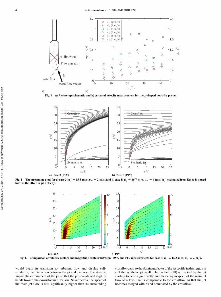
velocity U > 1 m∕s and 20% for U < 0.2 m∕s. The x-shaped hot-wire probe, as illustrated in Fig. 4a, is designed to measure 2D flows,
where the angle between themean flow and the probe axis is less than45 deg. However, the accuracy of this measurement drops as the flowangle α increases. This is demonstrated in Fig. 4b, which plots the
variations of the velocity-magnitude error (δU) and the flow-angleerror (δα) with α. This inaccuracy caused by a nonzero α has twoprimary sources, one of which is related to the error in measuring the
yaw coefficient [63] for both hot wires, and the other is attributable tothe error in aligning the probe axis with the incoming flow duringcalibration. However, these errors can be eliminated if α → 0 deg. Inthis experiment, α → 0 deg is achieved by affixing the hot-wireprobe to a holder positioned on a motorized rotary stage. We then
apply an iterative stage-control algorithm to automatically rotate thehot-wire probe to reduce α, so that the probe axis becomes alignedwith the local mean velocity vector. The setup for obtaining the flow
field of a transverse synthetic jet is also shown in Fig. 2, in which therotary stage is mounted on top of a linear traverse system. Thistraverse system is composed of two motorized linear stages that are
perpendicular to each other and traverse in the x-z plane. To acquirethe flow field, the stages are programmed and moved in discreteintervals in the x and z directions. At each location the iterative stage-control scheme is first performed to align the probe axis with the localmean flow and then the flow is sampled for 10 s at a rate of 50 kHz.For comparison and resolving the time-dependent vortical
structures, a PIV system is also employed to measure the same 2Dflow at the center plane of the transverse synthetic jets. This systemuses a high-speed CMOS camera (Phantom v210; 1280 × 800 px2,over 2000 fps) and a 20 mJ Nd:YLF laser (Quantronix Darwin Duo;γ � 527 nm, repetitions up to 10 kHz). Olive oil particles (∼1 μm)are generated by an atomizer to seed the flow field. For each test, thecamera and the laser are synchronized through the Insight 4Gsoftware by TSI Inc. to acquire the image pairs at a rate of f∕10 for 2 s(a total of 360–380 images depending on the jet actuation frequencyf). The trigger for the synthetic jet is synchronized with the PIVsystem and the trigger delay is adjusted to obtain the instantaneousflow field of the jet locked at a desired phase (10 per cycle), similar towhat was demonstrated by Yehoshua and Seifert [44]. Therefore, atime-averaged flow field can be obtained by averaging the phase-locked data of each cycle.
III. Preliminary Results
The modeling approach in this study, as will be introduced inSec. IV, is built on the mean velocity field of the center plane of atransverse synthetic jet. In this section, we first present the flow fieldobtained through HWA and PIV measurements to validate ourexperimental approach and provide a basic understanding of themean flow features. Then, the flow field data are analyzed to give thecenterline trajectory, which is compared among different cases toimply the bending characteristics.
A. Mean Flow Field
We start by showing streamlines of the mean flow field obtainedfrom PIV for two sample cases (cases 3 and 5) in Fig. 5. We thencompare HWA and PIV measurements by plotting the velocitymagnitude contours and vectors in Figs. 6 and 7. To optimize thesampling efficiency of theHWAmeasurement, the sampling region ispre-estimated to include only the mainstream of the jet flow so thatthe sampling grid becomes nonuniform. For comparison purposes,the PIV data in Figs. 6 and 7 are obtained by interpolating the originalhigher resolution data to the sampling locations of the correspondingHWA tests. Qualitatively agreement between HWA and PIVmeasurements can be observed from the streamline and the velocityvector plots. However, the PIV data seem to display a thinner jetregion compared with the HWA data in the velocity magnitudecontours. This reflects the size effect of the x-shaped hot-wire sensor,which may overestimate the velocities near but outside the coreregion of a jet, consequently expanding the core region. Furthercomparison of the performance between HWA and PIVmeasurements will be provided in the following sections.As observed from the contour plots in Figs. 6 and 7, the flow field
of a transverse synthetic jet resembles a typical jet in that it has a coreregion near the jet exit; however, it is asymmetric and deflected tosome extent. This apparent jet region extends only up to z � 15d orso, where the mainstream of the jet flow starts to bend significantlyand turn into the crossflow. This differentiation is used to identify twodynamically different regions for the case of a continuous jet, namely,the jet-dominated domain and the crossflow-dominated domain. Toaccount for the unique vortex formation effect in the jet-dominatedregion, the flow field of a transverse synthetic jet can be divided intothree regions: I) the synthetic jet region, II) the near field, and III) thefar field. In the synthetic jet region (I), which is the regionimmediately outside the jet orificewith z < 5d, the flow is dominatedby the periodic process of suction and vortex formation. This regiongenerally corresponds to the near field of a synthetic jet in static flow.However, as reported by Yehoshua and Seifert [44] and Jabbal andZhong [43], the formed vortex ring is asymmetric under the influenceof the crossflow as opposed to a free synthetic jet. In the near field (II),the region (5d ≤ z ≤ 15d) where an equivalent free synthetic jet
Table 1 Test matrix displaying the jet driving frequency (f), jetstroke ratio (L∕d), jet Reynolds number (Res �
Fig. 3 The crossflow velocity profiles at the streamwise location of thejet exit, for different wind tunnel speeds of 2, 4, and 6 m∕s. This velocitydata were obtained through PIV measurement.
Article in Advance / XIA AND MOHSENI 3
Dow
nloa
ded
by U
NIV
ER
SIT
Y O
F FL
OR
IDA
on
Nov
embe
r 3,
201
6 | h
ttp://
arc.
aiaa
.org
| D
OI:
10.
2514
/1.J
0548
80
would begin its transition to turbulent flow and display self-
similarity, the interaction between the jet and the crossflow starts to
impact the entrainment of the jet so that the jet spreads and slightly
bends toward the downstream direction. Nevertheless, the speed of
the main jet flow is still significantly higher than its surrounding
crossflow, and so the dominant factor of the jet profile in this region is
still the synthetic jet itself. The far field (III) is marked by the jet
starting to bend significantly and the decay in speed of the main jet
flow to a level that is comparable to the crossflow, so that the jet
becomes merged within and dominated by the crossflow.
0
0.4
0.8
1.2
1.6
2
2.4
0
a) b)
10 20 30 400
0.2
0.4
0.6
0.8
1
1.2
Fig. 4 a) A close-up schematic and b) errors of velocity measurement for the x-shaped hot-wire probe.
−5 0
a) Case 3 (PIV) b) Case 5 (PIV)
5 10 15 20 250
5
10
15
20
25
30
35
Synthetic jet
Crossflow
−5 0 5 10 15 20 250
5
10
15
20
25
30
35
Synthetic jet
Crossflow
Fig. 5 The streamline plots for a) case 3:wj � 15.3 m∕s, u∞ � 2 m∕s, and b) case 5:wj � 16.7 m∕s, u∞ � 4 m∕s.wj2 estimated from Eq. (14) is usedhere as the effective jet velocity.
−5
a) HWA b) PIV
0 5 10 15 20 250
5
10
15
20
25
30
35
0
2
4
6
8
10
−5 0 5 10 15 20 250
5
10
15
20
25
30
35
0
2
4
6
8
10
Fig. 6 Comparison of velocity vectors and magnitude contour between HWA and PIV measurements for case 3: wj � 15.3 m∕s, u∞ � 2 m∕s.
4 Article in Advance / XIA AND MOHSENI
Dow
nloa
ded
by U
NIV
ER
SIT
Y O
F FL
OR
IDA
on
Nov
embe
r 3,
201
6 | h
ttp://
arc.
aiaa
.org
| D
OI:
10.
2514
/1.J
0548
80
B. Jet Centerline Trajectory
The properties associated with the jet centerline, such as location
and velocities, are the main focus of this study. The centerline here
refers to the curve corresponding to the local maximum speed inside
themain jet region. To accurately identify the centerline locationwith
the experimentally obtained flow field, a contour-line-searching
algorithm is used based on the velocity-magnitude contours, as
illustrated in Fig. 8. Here, we first note that the PIV contour captures a
secondary jet stream that does not appear in the HWA contour.
Although more details are not presented here, we note that this
secondary jet stream is created by the trailing vortices, which are
formed after the pinch-off [11] of the leading vortex rings. Again, this
different flow feature likely reflects a finer spatial resolution of the
PIV measurement and the spatial-averaging effect of the HWA
measurement. The resultant centerline points are qualitatively
divided into two groups, the near-field and the far-field, based on
identifying the transitional region where the jet trajectory shows a
notably different bending trend. The same can be done for the other
cases and the results are compared in Fig. 9. A good agreement
between the HWA and PIV results can be confirmed for all cases.
−5 0 5 10 15 20 250
5
10
15
20
25
30
35
0
2
4
6
8
10
−5 0 5 10 15 20 250
5
10
15
20
25
30
35
0
2
4
6
8
10
a) HWA b) PIVFig. 7 Comparison of velocity vectors and magnitude contour between HWA and PIV measurements for case 5: wj � 16.7 m∕s, u∞ � 4 m∕s.
−5 0 5 10 15 20 250
5
10
15
20
25
30
35
0
5
10
15Near fieldFar field
−5 0 5 10 15 20 250
5
10
15
20
25
30
35
a) HWA b) PIV
Fig. 8 Velocity-magnitude contours and calculated centerline points obtained from a) HWA and b) PIV measurements, respectively, for case 3.
Fig. 9 The centerline points calculated from HWA and PIV data for a) cases 1–3 and b) cases 4–6.
Article in Advance / XIA AND MOHSENI 5
Dow
nloa
ded
by U
NIV
ER
SIT
Y O
F FL
OR
IDA
on
Nov
embe
r 3,
201
6 | h
ttp://
arc.
aiaa
.org
| D
OI:
10.
2514
/1.J
0548
80
Furthermore, we can conclude from Figs. 9a and 9b that both
increasing jet strength and weakening crossflow will decrease the
bending angle of the trajectory and increase the depth the jet flow
penetrates into the crossflow.
IV. Theoretical Modeling
As both continuous jets and synthetic jets are self-similar in the far
field, Krishnan and Mohseni [19] were able to model a round
synthetic jet in a quiescent environment using the Schlichting jet
solution [64,65], a model that was originally developed for a
continuous jet. Following the same idea, this study seeks to extend the
modeling approach of a transverse continuous jet to a transverse
synthetic jet. This is achieved by adopting Hasselbrink andMungal’s
model [59], which gives the similarity solutions of a transverse
continuous jet by applying conservation equations to a control
volume containing the mainstream of the jet in crossflow. By further
defining an effective synthetic jet velocity in a momentum
conservation sense, we obtain the similarity relations about the
centerline trajectory and velocity for a transverse synthetic jet.
A. Scaling Laws for a Transverse Synthetic Jet
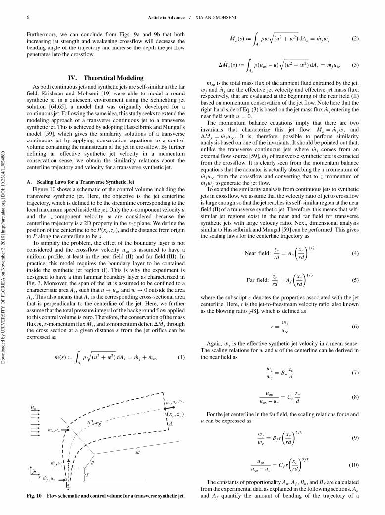
Figure 10 shows a schematic of the control volume including the
transverse synthetic jet. Here, the objective is the jet centerline
trajectory, which is defined to be the streamline corresponding to the
localmaximum speed inside the jet. Only the x-component velocityuand the z-component velocity w are considered because the
centerline trajectory is a 2D property in the x-z plane. We define the
position of the centerline to beP�xc; zc�, and the distance from origin
to P along the centerline to be s.To simplify the problem, the effect of the boundary layer is not
considered and the crossflow velocity u∞ is assumed to have a
uniform profile, at least in the near field (II) and far field (III). In
practice, this model requires the boundary layer to be contained
inside the synthetic jet region (I). This is why the experiment is
designed to have a thin laminar boundary layer as characterized in
Fig. 3. Moreover, the span of the jet is assumed to be confined to a
characteristic area As, such that u → u∞ and w → 0 outside the areaAs. This also means that As is the corresponding cross-sectional area
that is perpendicular to the centerline of the jet. Here, we further
assume that the total pressure integral of the background flow applied
to this control volume is zero. Therefore, the conservation of themass
flux _m, z-momentum flux _Mz, and x-momentumdeficitΔ _Mx through
the cross section at a given distance s from the jet orifice can be
expressed as
_m�s� ≔ZAs
��������������������u2 � w2�
qdAs � _mj � _m∞ (1)
_Mz�s� ≔ZAs
ρw����������������������u2 � w2�
qdAs � _mjwj (2)
Δ _Mx�s� ≔ZAs
ρ�u∞ − u�����������������������u2 � w2�
qdAs � _mju∞ (3)
_m∞ is the total mass flux of the ambient fluid entrained by the jet.wj and _mj are the effective jet velocity and effective jet mass flux,respectively, that are evaluated at the beginning of the near field (II)based on momentum conservation of the jet flow. Note here that theright-hand side of Eq. (3) is based on the jet mass flux _mj entering thenear field with u � 0.The momentum balance equations imply that there are two
invariants that characterize this jet flow: _Mz � _mjwj andΔ _Mx � _mju∞. It is, therefore, possible to perform similarityanalysis based on one of the invariants. It should be pointed out that,unlike the transverse continuous jets where _mj comes from anexternal flow source [59], _mj of transverse synthetic jets is extractedfrom the crossflow. It is clearly seen from the momentum balanceequations that the actuator is actually absorbing the x momentum of_mju∞ from the crossflow and converting that to z momentum of_mjwj to generate the jet flow.To extend the similarity analysis from continuous jets to synthetic
jets in crossflow, we assume that the velocity ratio of jet to crossflowis large enough so that the jet reaches its self-similar region at the nearfield (II) of a transverse synthetic jet. Therefore, this means that self-similar jet regions exist in the near and far field for transversesynthetic jets with large velocity ratio. Next, dimensional analysissimilar to Hasselbrink andMungal [59] can be performed. This givesthe scaling laws for the centerline trajectory as
Near field:zcrd
� An
�xcrd
�1∕2
(4)
Far field:zcrd
� Af
�xcrd
�1∕3
(5)
where the subscript c denotes the properties associated with the jetcenterline. Here, r is the jet-to-freestream velocity ratio, also knownas the blowing ratio [48], which is defined as
r � wj
u∞(6)
Again, wj is the effective synthetic jet velocity in a mean sense.The scaling relations for w and u of the centerline can be derived inthe near field as
wj
wc
� Bn
zcd
(7)
u∞u∞ − uc
� Cn
zcd
(8)
For the jet centerline in the far field, the scaling relations forw andu can be expressed as
wj
wc
� Bfr
�xcrd
�2∕3
(9)
u∞u∞ − uc
� Cfr
�xcrd
�2∕3
(10)
The constants of proportionality An, Af, Bn, and Bf are calculatedfrom the experimental data as explained in the following sections.An
and Af quantify the amount of bending of the trajectory of aFig. 10 Flow schematic and control volume for a transverse synthetic jet.
6 Article in Advance / XIA AND MOHSENI
Dow
nloa
ded
by U
NIV
ER
SIT
Y O
F FL
OR
IDA
on
Nov
embe
r 3,
201
6 | h
ttp://
arc.
aiaa
.org
| D
OI:
10.
2514
/1.J
0548
80
transverse synthetic jet in the near and far field, respectively. Largervalues of the coefficients essentially correspond to less bending. Bn
andBf quantify the decay of the z-component velocity,where a largervalue of the coefficient indicates a stronger decay behavior. It hasbeen found that, for a continuous jet with large velocity ratio, An, Af,Bn, and Bf are constants (around 2.5, 1.6, 0.16, and 0.94,respectively) [59]. This suggests the existence of a common set ofscaling laws for continuous jets. In this study, a main objective is toextend this unified model to synthetic jets and find the coefficientscorresponding to the scaling laws.Before we proceed, it is important to note that the scaling laws
associated with the trajectory and the velocity wc [Eqs. (4), (5), (7),and (9)] are obtained with the assumption of invariant _Mz, whereasthe scaling laws associated with uc [Eqs. (8) and (10)] are derivedbased on invariance ofΔ _Mx. Therefore, the validity of these two setsof scaling laws depends on the invariance of _Mz and Δ _Mx,respectively. For the former, the following section will propose aneffective jet velocity that conserves _Mz by nature. For the latter, itsvalidity will be discussed in Sec. V.C.
B. Effective Jet Velocity and Velocity Ratio
The previous section adopts the scaling laws for a transversecontinuous jet and applies a similar approach to the case of a syntheticjet. Essentially, this model is based upon the assumption that aconstant momentum flux _Mz in the z direction is being added to thenear field (II) of the transverse synthetic jet. As a result, an effectivejet velocity, wj, can be defined so that _Mz � _mjwj. However,contrary to the assumption, the momentum flux generated by asynthetic jet actuator is pulsed in nature. To account for thedifference, a momentum-addition approach is incorporated into themodel for synthetic jets.Because the z-momentum flux is assumed to be conserved in the
near and far field of a transverse jet, the averaged momentum flux atthe jet exit should equal _Mz during an entire actuation period. Basedon this model and a slug assumption that assumes the fluid to beejected with a “top-hat” velocity profile at a constant rate during each
stroke,Krishnan andMohseni [19] estimated the effective jet velocityat the jet exit of a synthetic jet to be
wj1 ����2
pfL (11)
Based on this effective jet velocity, the jet-to-freestream velocityratio r1 is calculated using Eq. (6) and listed in Table 2.Recently, Xia and Mohseni [16] demonstrated that, in the absence
of crossflow, the far-field momentum flux of a round synthetic jet isalways smaller than the prediction from the slug model. They furtherpointed out that the deceleration effect during the suction phase is onereason for the mismatch. The other is associated with the pinch-offprocess [11,12,66,67] that results in the generation of trailing vorticalstructures containing a much smaller momentum flux per unitcirculation, in comparison with that of the leading vortex rings. Theyfurther showed that the primary contribution to the far-fieldmomentum flux is the impulse carried by the fully-developed vortexring formed during each stroke. Moreover, Jabbal and Zhong [43]also showed that the penetration and the core flow of a transversesynthetic jet are determined by the trajectory of thevortex rings. It canbe implied from their study that the main-stream trajectory of atransverse synthetic jet is primarily attributable to the propagation ofthe leading vortex rings, whereas the trailing vortical structures movealong trajectories away from the jet centerline, as shown in Fig. 1.From this notion, the initial momentum flux of the transversesynthetic jet may be calculated with the impulse of the vortex rings.Based on this model [16], _Mz in Eq. (2) could be calculated from
_Mz �ρπ3
32f2d2L2α20C (12)
where α0 � 1.2 and C is the fraction of the total circulation in thevortex ring. C can be roughly estimated by
C ��
1 if L∕d < L�∕d�L�∕d�∕�L∕d� if L∕d > L�∕d (13)
where L� is the characteristic stroke length associated with the jetformation number [11,12,16] for synthetic jets. Subsequently, theeffective jet velocity wj can be obtained by
wj2 ��������2C
p
4πα0fL (14)
Thus, a novel jet-to-freestream velocity ratio, r2, is estimated withwj from Eq. (14) and listed in Table 2. We now evaluate theperformance of Eqs. (11) and (14) by comparing the predicted jeteffective velocities with experimental data of the jet centerlinevelocities, as shown in Fig. 11. We can generally observe that the
Table 2 Effective jet velocities andvelocity ratios for all cases
a) HWA b) PIVFig. 11 Variation of time-averaged z-component velocity along the centerline for different transverse synthetic jets, obtained from a) HWA and b) PIVmeasurements.
Article in Advance / XIA AND MOHSENI 7
Dow
nloa
ded
by U
NIV
ER
SIT
Y O
F FL
OR
IDA
on
Nov
embe
r 3,
201
6 | h
ttp://
arc.
aiaa
.org
| D
OI:
10.
2514
/1.J
0548
80
peak centerline velocities obtained from both HWA and PIVmeasurements are better predicted by wj2. Therefore, the following
analysiswill be based on the effective jet velocitywj2 and thevelocityratio r2. It should be noted that although the overall agreementbetween the twomeasurements is good in the far field, the HWA datafor some cases seem to measure slightly higher peak velocities in the
near field compared with the PIV data. A similar observation has alsobeen reported by Yehoshua and Seifert [44], who attributed the
different mean velocities to the differences in spatial and temporalresolutions between HWA and PIV measurements.
V. Model Validation
This section will provide validation of the scaling laws obtained inSec. IV for the centerline trajectory and velocities of transversesynthetic jets, based on both HWA and PIV velocity field data. The
0 5 10 15 20 250
a) HWA b) PIV
5
10
15
20
25
30
Increasi
ng velocity
ratio
0 5 10 15 20 250
5
10
15
20
25
30
Increasi
ng velocity
ratio
Fig. 12 The centerline trajectories (solid line and dashed line represent the near field and far field, respectively) obtained by fitting Eqs. (4) and (5) to thecalculated centerline points in Fig. 9.
0 0.5 1 1.50
1
2
3
4
5
Continuous j
et
0 0.5 1 1.5 20
1
2
3
4
5
6
Continuous jet
0 0.5 1 1.50
1
2
3
4
5
a) Near field, HWA b) Far field, HWA
c) Near field, PIV d) Far field, PIV
Continuous j
et
0 0.5 1 1.5 20
1
2
3
4
5
6
Continuous jet
Fig. 13 Validation of the scaling relations [Eqs. (4) and (5) represented by the dashed lines] for the trajectory of transverse synthetic jets.
8 Article in Advance / XIA AND MOHSENI
Dow
nloa
ded
by U
NIV
ER
SIT
Y O
F FL
OR
IDA
on
Nov
embe
r 3,
201
6 | h
ttp://
arc.
aiaa
.org
| D
OI:
10.
2514
/1.J
0548
80
objective here is to quantify the coefficients corresponding to the
scaling laws and then verify the universality of the coefficients for
transverse synthetic jets with different velocity ratios.
A. Trajectory Relations
The centerline trajectories have been obtained from flow field data
in Sec. III.B. We now move on to verify the model proposed in
Sec. IV by fitting Eqs. (4) and (5) to the centerline points in the near
and far field, respectively. The results are shown in Fig. 12 and
corresponds to the data presented in Fig. 9. It can be observed that the
scaling laws presented in Eqs. (4) and (5) accurately capture the
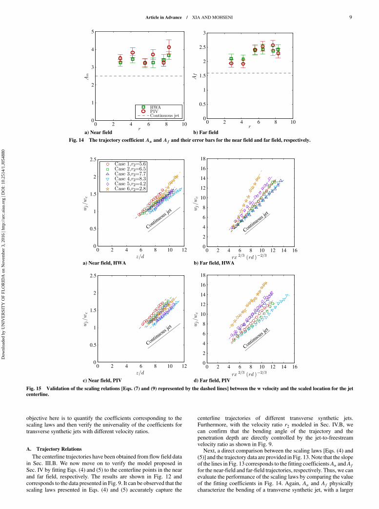
centerline trajectories of different transverse synthetic jets.Furthermore, with the velocity ratio r2 modeled in Sec. IV.B, wecan confirm that the bending angle of the trajectory and thepenetration depth are directly controlled by the jet-to-freestreamvelocity ratio as shown in Fig. 9.Next, a direct comparison between the scaling laws [Eqs. (4) and
(5)] and the trajectory data are provided in Fig. 13. Note that the slopeof the lines in Fig. 13 corresponds to the fitting coefficientsAn andAf
for the near-field and far-field trajectories, respectively. Thus, we canevaluate the performance of the scaling laws by comparing the valueof the fitting coefficients in Fig. 14. Again, An and Af physicallycharacterize the bending of a transverse synthetic jet, with a larger
0
a) Near field b) Far field
2 4 6 8 100
1
2
3
4
5
0 2 4 6 8 100
0.5
1
1.5
2
2.5
3
Fig. 14 The trajectory coefficientAn and Af and their error bars for the near field and far field, respectively.
0 2 4 6 8 10 120
0.5
1
1.5
2
2.5
Continuous je
t
0 2 4 6 8 10 12 14 160
2
4
6
8
10
12
14
16
18
Continuous j
et
0 2 4 6 8 10 120
0.5
1
1.5
2
2.5
Continuous je
t
0 2 4 6 8 10 12 14 160
2
4
6
8
10
12
14
16
18
Continuous j
et
a) Near field, HWA b) Far field, HWA
c) Near field, PIV d) Far field, PIV
Fig. 15 Validation of the scaling relations [Eqs. (7) and (9) represented by the dashed lines] between the w velocity and the scaled location for the jetcenterline.
Article in Advance / XIA AND MOHSENI 9
Dow
nloa
ded
by U
NIV
ER
SIT
Y O
F FL
OR
IDA
on
Nov
embe
r 3,
201
6 | h
ttp://
arc.
aiaa
.org
| D
OI:
10.
2514
/1.J
0548
80
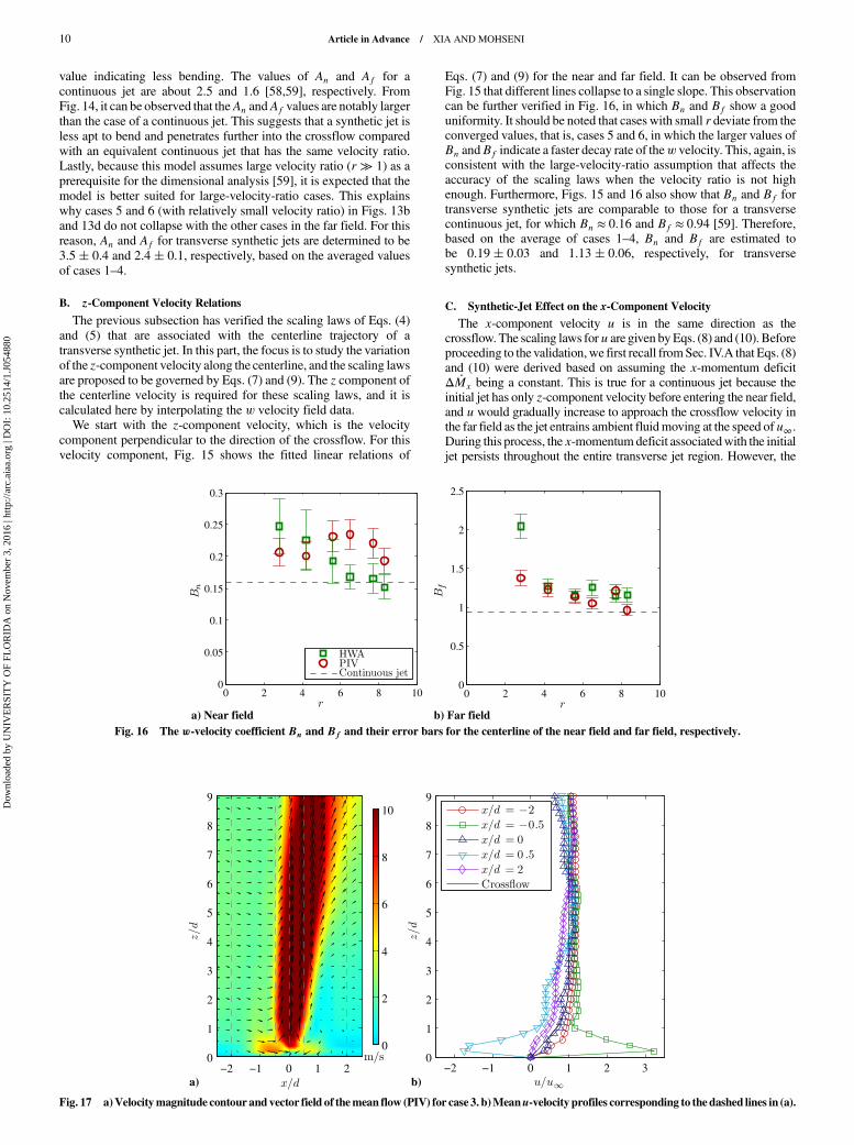
value indicating less bending. The values of An and Af for a
continuous jet are about 2.5 and 1.6 [58,59], respectively. From
Fig. 14, it can be observed that theAn andAf values are notably larger
than the case of a continuous jet. This suggests that a synthetic jet is
less apt to bend and penetrates further into the crossflow compared
with an equivalent continuous jet that has the same velocity ratio.
Lastly, because this model assumes large velocity ratio (r ≫ 1) as aprerequisite for the dimensional analysis [59], it is expected that the
model is better suited for large-velocity-ratio cases. This explains
why cases 5 and 6 (with relatively small velocity ratio) in Figs. 13b
and 13d do not collapse with the other cases in the far field. For this
reason, An and Af for transverse synthetic jets are determined to be
3.5� 0.4 and 2.4� 0.1, respectively, based on the averaged values
of cases 1–4.
B. z-Component Velocity Relations
The previous subsection has verified the scaling laws of Eqs. (4)
and (5) that are associated with the centerline trajectory of a
transverse synthetic jet. In this part, the focus is to study the variation
of the z-component velocity along the centerline, and the scaling laws
are proposed to be governed by Eqs. (7) and (9). The z component of
the centerline velocity is required for these scaling laws, and it is
calculated here by interpolating the w velocity field data.
We start with the z-component velocity, which is the velocity
component perpendicular to the direction of the crossflow. For this
velocity component, Fig. 15 shows the fitted linear relations of
Eqs. (7) and (9) for the near and far field. It can be observed fromFig. 15 that different lines collapse to a single slope. This observationcan be further verified in Fig. 16, in which Bn and Bf show a gooduniformity. It should be noted that cases with small r deviate from theconverged values, that is, cases 5 and 6, in which the larger values ofBn andBf indicate a faster decay rate of thew velocity. This, again, isconsistent with the large-velocity-ratio assumption that affects theaccuracy of the scaling laws when the velocity ratio is not highenough. Furthermore, Figs. 15 and 16 also show that Bn and Bf fortransverse synthetic jets are comparable to those for a transversecontinuous jet, for which Bn ≈ 0.16 and Bf ≈ 0.94 [59]. Therefore,based on the average of cases 1–4, Bn and Bf are estimated tobe 0.19� 0.03 and 1.13� 0.06, respectively, for transversesynthetic jets.
C. Synthetic-Jet Effect on the x-Component Velocity
The x-component velocity u is in the same direction as thecrossflow. The scaling laws foru are given byEqs. (8) and (10). Beforeproceeding to the validation,we first recall fromSec. IV.A that Eqs. (8)and (10) were derived based on assuming the x-momentum deficitΔ _Mx being a constant. This is true for a continuous jet because theinitial jet has only z-component velocity before entering the near field,and u would gradually increase to approach the crossflow velocity inthe far field as the jet entrains ambient fluidmoving at the speed ofu∞.During this process, the x-momentumdeficit associatedwith the initialjet persists throughout the entire transverse jet region. However, the
0 2 4 6 8 100
0.05
a) Near field b) Far field
0.1
0.15
0.2
0.25
0.3
0 2 4 6 8 100
0.5
1
1.5
2
2.5
Fig. 16 The w-velocity coefficient Bn and Bf and their error bars for the centerline of the near field and far field, respectively.
−2 −1 0 1 20
a) b)
1
2
3
4
5
6
7
8
9
0
2
4
6
8
10
−2 −1 0 1 2 30
1
2
3
4
5
6
7
8
9
Fig. 17 a)Velocitymagnitude contour and vector field of themean flow (PIV) for case 3. b)Meanu-velocity profiles corresponding to the dashed lines in (a).
10 Article in Advance / XIA AND MOHSENI
Dow
nloa
ded
by U
NIV
ER
SIT
Y O
F FL
OR
IDA
on
Nov
embe
r 3,
201
6 | h
ttp://
arc.
aiaa
.org
| D
OI:
10.
2514
/1.J
0548
80
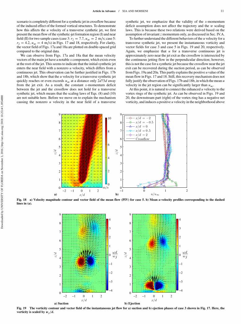
scenario is completely different for a synthetic jet in crossflow because
of the induced effect of the formed vortical structures. To demonstrate
how this affects the u velocity of a transverse synthetic jet, we first
present themean flow of the synthetic-jet formation region (I) and near
field (II) for two sample cases (case 3: r2 � 7.7, u∞ � 2 m∕s; case 5:r2 � 4.2, u∞ � 4 m∕s) in Figs. 17 and 18, respectively. For clarity,
the vector field of Figs. 17a and 18a are plotted on double-spaced grid
compared to the original data.
We can observe from Figs. 17a and 18a that the mean velocity
vectors of themain jet have a notable x component, which exists even
at the root of the jet. This seems to indicate that the initial synthetic jet
enters the near field with a nonzero u velocity, which differs from a
continuous jet. This observation can be further justified in Figs. 17b
and 18b, which show that the u velocity for a transverse synthetic jetquickly reaches or even exceeds u∞ at a distance only 2d?3d away
from the jet exit. As a result, the constant x-momentum deficit
between the jet and the crossflow does not hold for a transverse
synthetic jet, which means that the scaling laws of Eqs. (8) and (10)
are not suitable here. Before we move on to explain the mechanism
causing the nonzero u velocity in the near field of a transverse
synthetic jet, we emphasize that the validity of the x-momentum
deficit assumption does not affect the trajectory and the w scaling
laws. This is because these two relations were derived based on the
assumption of invariant zmomentum only, as discussed in Sec. IV.A.
To further understand the different behaviors of the u velocity for atransverse synthetic jet, we present the instantaneous vorticity and
vector fields for case 3 and case 5 in Figs. 19 and 20, respectively.
Again, we emphasize that u for a transverse continuous jet is
approximately zero near the jet exit as the crossflow is intersected by
the continuous jetting flow in the perpendicular direction; however,
this is not the case for a synthetic jet because the crossflow near the jet
exit can be recovered during the suction period, as can be observed
fromFigs. 19a and 20a. This partly explains the positiveuvalue of themean flow in Figs. 17 and 18. Still, this recoverymechanism does not
fully justify the observation of Figs. 17b and 18b, inwhich themeanuvelocity in the jet region can be significantly larger than u∞.At this point, it is natural to connect the enhanced u velocity to the
vortex rings of the synthetic jet. As can be observed in Figs. 19 and
20, the downstream part (right) of the vortex ring has a negative net
vorticity, and induces a positive uvelocity in the neighborhood above
−2 −1 0 1 20
a) b)
1
2
3
4
5
6
7
8
9
0
2
4
6
8
10
−1 0 1 20
1
2
3
4
5
6
7
8
9
Fig. 18 a) Velocity magnitude contour and vector field of the mean flow (PIV) for case 5. b) Mean u-velocity profiles corresponding to the dashedlines in (a).
−2 −1 0 1 20
a) Suction b) Ejection
1
2
3
4
5
6
7
8
9
−4
−3
−2
−1
0
1
2
3
4
−2 −1 0 1 20
1
2
3
4
5
6
7
8
9
−4
−3
−2
−1
0
1
2
3
4
Fig. 19 The vorticity contour and vector field of the instantaneous jet flow for a) suction and b) ejection phases of case 3 shown in Fig. 17. Here, thevorticity is scaled by wj∕d.
Article in Advance / XIA AND MOHSENI 11
Dow
nloa
ded
by U
NIV
ER
SIT
Y O
F FL
OR
IDA
on
Nov
embe
r 3,
201
6 | h
ttp://
arc.
aiaa
.org
| D
OI:
10.
2514
/1.J
0548
80
and a negative uvelocity in the neighborhood below. On the contrary,the upstream part of the vortex ring induces a positive u velocitybelow it and a negative u velocity above it. Thus, the total induced uvelocity should be symmetric in themean sense for a synthetic jet in aquiescent environment. However, for a synthetic jet in crossflow,these induced effects cause the crossflow to be enhanced in theregions below the upstream-part (left) vortex ring and above thedownstream-part vortex ring, which is evident from the velocityvectors near the vortex rings (vortex pairs in the 2D plot) shown inFigs. 19 and 20. Based on this observation, we can conclude that theinteractions between the crossflow and the vortex ring result in anasymmetrically induced effect of the vortex ring, which is eventuallytranslated into an enhanced mean u velocity. Because of thisasymmetrically enhanced flow in the vicinity of the vortex ring, thevortex ring axis also becomes tilted, as has been reported by JabbalandZhong [43]. The finding of the increased crossflowvelocity in thenear field indicates that the interaction between the synthetic jet andthe crossflow also enhances the flow momentum outside theboundary layer. This could be an auxiliary contribution to themomentummixingmechanism that has been proposed to cause delayof flow separation [36–39].Lastly, we note that the effect of the crossflow boundary layer on
the formation and evolution of the vortex ring is marginal in thisstudy. According to Yehoshua and Seifert [44] and Jabbal and Zhong[43], the established vorticity field associatedwith the boundary layerwould cancel out the vorticity of the upstream part of the vortex ringand adds to the vorticity of the downstream part, which might createfurther asymmetric enhancement of the u velocity. However, in thecurrent study of strong synthetic jet versus weak crossflow, theaverage nondimensional vorticity, �ωd∕wj, for the boundary layer isaround 0.1 and the thickness is less than 3d. In this case, the vorticitydistribution of the vortex ring is hardly affected by the weak and thinboundary layer. Quantitatively, for the fully generated vortex ringlocated at the center of Fig. 19a, the nondimensional circulation,Γ∕�wjd�, corresponding to the upstream part and the downstreampart are calculated to be 2.68 and −2.60, respectively, using theQ-criterion [68]. Similarly, the two circulations for the fullydeveloped vortex ring in Fig. 20a are estimated to be 2.90 and−2.99,respectively. Therefore, the small difference between the circulationsof the upstream-part and downstream-part vortex ring demonstrates asmall influence of the crossflow boundary layer.
VI. Conclusions
The flow field of strong synthetic jets in crossflow is investigatedusing HWA and PIV. An automated rotary stage together with an
iterative angle-finding algorithm is adopted to improve the accuracyof the HWA. Similarity analysis is successfully extended fromcontinuous jets to model the centerline trajectory and velocity ofsynthetic jets in crossflow, based on the two invariants of the flow, thez-direction momentum and x-direction momentum deficit.Experimental data are used to validate the scaling laws for thecenterline velocity and trajectory of the jet, with different jet-to-freestream velocity ratios being tested. The HWA and PIVmeasurements generally have a goodmatchingwith each other for thetested mean velocity field of transverse jet. However, because of thespatial averaging effect, the HWA anemometry tends to measure alarger jet region. It is found that the effective jet velocity is betterpredicted in a momentum conservation sense, based on themomentum flux of the leading vortex rings instead of the momentumflux of the ejected slug at the jet exit.The scaling laws for the trajectory and the z-component velocity of
a transverse synthetic jet are given by Eqs. (4), (5), (7), and (9),whereas the corresponding coefficients, An, Af, Bn, and Bf, aredetermined to be 3.5, 2.4, 0.19, and 1.13, respectively. These scalingcoefficients show good consistency for different synthetic jets withlarge velocity ratios, whereas significant variation of the coefficientscan be observed for the small-velocity-ratio cases. This observation isconsistent with the basic assumption of the scaling laws that the jet-to-velocity ratio should be significantly larger than unity. Bycomparing the scaling coefficients for the centerline trajectorybetween synthetic jets and continuous jets, it is concluded that asynthetic jet is less likely to deflect and penetrates further than acontinuous jet.Another finding of this study is that the u velocity of a transverse
synthetic jet displays a dramatic difference from that of a continuousjet. Specifically, u is observed to be notably increased in the near fieldof a transverse synthetic jet, whereas u for a continuous jet isapproximately zero in the same region. Thus, the scaling laws for theu velocity are not applicable for the case of a transverse synthetic jet.This increased u velocity can be attributed to an asymmetric inducedeffect by the vortex rings, and it indicates an enhanced momentum ofthe crossflow outside the boundary layer. Therefore, the enhancedcrossflow could provide additional contribution to enhancingmomentum inside the boundary layer and delaying flow separation,by means of momentum mixing across the boundary layer.
Acknowledgments
This work is supported by a grant from the Office of NavalResearch. We are grateful to the referees for their valuable commentsthat lead to great improvements of this paper. We would like to
−2 −1 0 1 20
1
2
3
4
5
6
7
8
9
−4
−3
−2
−1
0
1
2
3
4
−2 −1 0 1 20
1
2
3
4
5
6
7
8
9
−4
−3
−2
−1
0
1
2
3
4
a) Suction b) Ejection
Fig. 20 The vorticity contour and vector field of the instantaneous jet flow for a) suction and b) ejection phases of case 5 shown in Fig. 18.
12 Article in Advance / XIA AND MOHSENI
Dow
nloa
ded
by U
NIV
ER
SIT
Y O
F FL
OR
IDA
on
Nov
embe
r 3,
201
6 | h
ttp://
arc.
aiaa
.org
| D
OI:
10.
2514
/1.J
0548
80
appreciateAdamDeVoria and Thomas Linehan for their assistance insetting up the particle image velocimetry experiment. We would liketo thankMichael Kreig, YimingXu, and Peter Zhang for their helpfulcomments.
References
[1] Smith, B. L., andGlezer, A., “The Formation andEvolution of SyntheticJets,” Physics of Fluids, Vol. 10, No. 9, 1998, pp. 2281–2297.doi:10.1063/1.869828
[2] Glezer, A., and Amitay, M., “Synthetic Jets,” Annual Review of Fluid
Mechanics, Vol. 34, No. 1, 2002, pp. 503–529.doi:10.1146/annurev.fluid.34.090501.094913
[3] Cattafesta, L. N., and Sheplak,M., “Actuators for Active FlowControl,”Annual Review of Fluid Mechanics, Vol. 43, No. 1, 2011, pp. 247–272.doi:10.1146/annurev-fluid-122109-160634
[4] Mohseni, K., and Mittal, R., Synthetic Jets: Fundamentals and
Applications, CRC Press, Boca Raton, FL, 2014, Chaps. 1, 6, 9, 10.[5] O’Dor, R. K., “The Forces Acting on Swimming Squid,” Journal of
Experimental Biology, Vol. 137, No. 1, 1988, pp. 421–442.[6] Krieg, M., and Mohseni, K., “Thrust Characterization of a Bioinspired
Vortex Ring Thruster for Locomotion of Underwater Robots,” IEEE
Journal of Oceanic Engineering, Vol. 33, No. 2, 2008, pp. 123–132.doi:10.1109/JOE.2008.920171
[7] Maxworthy, T., “Some Experimental Studies of Vortex Rings,” Journalof Fluid Mechanics, Vol. 81, No. 3, 1977, pp. 465–495.doi:10.1017/S0022112077002171
[8] Saffman, P. G., “The Number of Waves on Unstable Vortex Rings,”Journal of Fluid Mechanics, Vol. 84, No. 4, 1978, pp. 625–639.doi:10.1017/S0022112078000385
[9] Didden, N., “On the Formation of Vortex Rings: Rolling-Up andProduction of Circulation,” Zeitschrift für AngewandteMathematik und
Physik, Vol. 30, No. 1, 1979, pp. 101–116.doi:10.1007/BF01597484
[10] Glezer, A., “The Formation of Vortex Rings,”Physics of Fluids, Vol. 31,No. 12, 1988, pp. 3532–3542.doi:10.1063/1.866920
[11] Gharib, M., Rambod, E., and Shariff, K., “A Universal Time Scale forVortex Ring Formation,” Journal of Fluid Mechanics, Vol. 360, 1998,pp. 121–140.doi:10.1017/S0022112097008410
[12] Mohseni, K., and Gharib, M., “A Model for Universal Time Scale ofVortex Ring Formation,” Physics of Fluids, Vol. 10, No. 10, 1998,pp. 2436–2438.doi:10.1063/1.869785
[13] Rosenfeld, M., Rambod, E., and Gharib, M., “Circulation andFormation Number of Laminar Vortex Rings,” Journal of Fluid
Mechanics, Vol. 376, 1998, pp. 297–318.doi:10.1017/S0022112098003115
[14] Smith, B. L., and Swift, G. W., “Synthetic Jets at Larger ReynoldsNumber and Comparison to Continuous Jets,”AIAAPaper 2001-3030,June 2001.
[15] Holman, R., Utturkar, Y., Mittal, R., Smith, B. L., and Cattafesta, L.,“Formation Criterion for Synthetic Jets,”AIAA Journal, Vol. 43, No. 10,2005, pp. 2110–2116.doi:10.2514/1.12033
[16] Xia, X., and Mohseni, K., “Far-Field Momentum Flux of High-Frequency Axisymmetric Synthetic Jets,” Physics of Fluids, Vol. 27,No. 11, 2015, Paper 115101.doi:10.1063/1.4935011
[18] Mallinson, S. G., Hong, G., and Reizes, J. A., “Some Characteristics ofSynthetic Jets,” AIAA Paper 1999-3651, 1999.
[19] Krishnan, G., and Mohseni, K., “Axisymmetric Synthetic Jets: AnExperimental and Theoretical Examination,” AIAA Journal, Vol. 47,No. 10, 2009, pp. 2273–2283.doi:10.2514/1.42967
[20] Krishnan, G., and Mohseni, K., “An Experimental and AnalyticalInvestigation of Rectangular Synthetic Jets,” ASME Journal of Fluids
Engineering, Vol. 131, No. 12, 2009, Paper 121101.doi:10.1115/1.4000422
[21] Cater, J. E., and Soria, J., “TheEvolution ofRoundZero-Net-Mass-FluxJets,” Journal of Fluid Mechanics, Vol. 472, 2002, pp. 167–200.doi:10.1017/S0022112002002264
[22] Smith, B. L., and Swift, G. W., “AComparison Between Synthetic Jetsand Continuous Jets,” Experiments in Fluids, Vol. 34, No. 4, 2003,
pp. 467–472.doi:10.1007/s00348-002-0577-6
[23] Mohseni, K., “Pulsatile Vortex Generators for Low-SpeedManeuveringof Small Underwater Vehicles,” Ocean Engineering, Vol. 33, No. 16,2006, pp. 2209–2223.doi:10.1016/j.oceaneng.2005.10.022
[24] Seifert, A., Bachar, T., Koss, D., Shepshelovich, M., andWygnanski, I.,“Oscillatory Blowing: A Tool to Delay Boundary-Layer Separation,”AIAA Journal, Vol. 31, No. 11, 1993, pp. 2052–2060.doi:10.2514/3.49121
[25] Amitay,M., andGlezer, A., “Role ofActuation Frequency in ControlledFlowReattachment over a StalledAirfoil,”AIAAJournal, Vol. 40,No. 2,2002, pp. 209–216.doi:10.2514/2.1662
[26] Amitay, M., and Glezer, A., “Controlled Transients of FlowReattachment over Stalled Airfoils,” International Journal of Heat
and Fluid Flow, Vol. 23, No. 5, 2002, pp. 690–699.doi:10.1016/S0142-727X(02)00165-0
[27] Yehoshua, T., and Seifert, A., “Active Boundary Layer Tripping UsingOscillatory Vorticity Generator,” Aerospace Science and Technology,Vol. 10, No. 3, 2006, pp. 175–180.doi:10.1016/j.ast.2005.10.007
[28] Zhang, S., and Zhong, S., “Experimental Investigation of FlowSeparation Control Using an Array of Synthetic Jets,” AIAA Journal,Vol. 48, No. 3, 2010, pp. 611–623.doi:10.2514/1.43673
[29] Seifert, A., Eliahu, S., Greenblatt, D., and Wygnanski, I., “Use ofPiezoelectric Actuators for Airfoil Separation Control,” AIAA Journal,Vol. 36, No. 8, 1998, pp. 1535–1537.doi:10.2514/2.549
[30] Amitay, M., Smith, D. R., Kibens, V., Parekh, D. E., and Glezer, A.,“Aerodynamic Flow Control over an Unconventional Airfoil UsingSynthetic JetActuators,”AIAAJournal,Vol. 39,No. 3, 2001, pp. 361–370.doi:10.2514/2.1323
[31] Mittal, R., and Rampunggoon, P., “On theVirtual Aeroshaping Effect ofSynthetic Jets,” Physics of Fluids, Vol. 14, No. 4, 2002, pp. 1533–1536.doi:10.1063/1.1453470
[32] Gilarranz, J. L., Traub, L. W., and Rediniotis, O. K., “A New Class ofSynthetic JetActuators—Part II: Application to FlowSeparationControl,”ASMEJournal of Fluids Engineering, Vol. 127,No. 2, 2005, pp. 377–387.doi:10.1115/1.1882393
[33] Raju, R., Mittal, R., and Cattafesta, L., “Dynamics of Airfoil SeparationControl Using Zero-Net-Mass-Flux Forcing,” AIAA Journal, Vol. 46,No. 12, 2008, pp. 3103–3115.doi:10.2514/1.37147
[34] Williams, D., Kerstens, W., Pfeiffer, J., King, R., and Colonius, T.,“UnsteadyLift Suppressionwith aRobustClosedLoopController,”ActiveFlow Control II, edited by King, R., Springer, Berlin, 2010, pp. 19–30.
[35] Zhang, Q., and Bodony, D. J., “Numerical Simulation of Two-Dimensional Acoustic Liners with High-Speed Grazing Flow,” AIAA
Journal, Vol. 49, No. 2, 2011, pp. 365–382.doi:10.2514/1.J050597
[36] Smith, D. R., “Interaction of a Synthetic Jet with a Crossflow BoundaryLayer,” AIAA Journal, Vol. 40, No. 11, 2002, pp. 2277–2288.doi:10.2514/2.1564
[37] Jabbal, M., and Zhong, S., “The Near Wall Effect of Synthetic Jets in aBoundary Layer,” International Journal of Heat and Fluid Flow,Vol. 29, No. 1, 2008, pp. 119–130.doi:10.1016/j.ijheatfluidflow.2007.07.011
[38] Zhong, S., and Zhang, S., “Further Examination of the Mechanism ofRound Synthetic Jets in Delaying Turbulent Flow Separation,” Flow,
Turbulence, and Combustion, Vol. 91, No. 1, 2013, pp. 177–208.doi:10.1007/s10494-013-9469-5
[39] Wen, X., and Tang, H., “On Hairpin Vortices Induced by CircularSynthetic Jets in Laminar and Turbulent Boundary Layers,” Computersand Fluids, Vol. 95, 2014, pp. 1–18.doi:10.1016/j.compfluid.2014.02.002
[40] Smith, D. R., Amitay, M., Kibens, V., Parekh, D., and Glezer, A.,“Modification of Lifting Body Aerodynamics Using Synthetic JetActuators,” Proceedings of the AIAA Aerospace Sciences Meeting and
Exhibit, AIAA Paper 1998-0209, Jan. 1998.[41] Duvigneau, R., and Visonneau, M., “Simulation and Optimization of
Stall Control for an Airfoil with a Synthetic Jet,” Aerospace Science andTechnology, Vol. 10, No. 4, 2006, pp. 279–287.doi:10.1016/j.ast.2006.01.002
[42] Mittal, R., Rampunggoon, P., and Udaykumar, H. S., “Interaction of aSynthetic Jet with a Flat Plate Boundary Layer,” Proceedings of the
AIAA Computational Fluid Dynamics Conference, AIAA Paper 2001-2773, June 2001.
[43] Jabbal, M., and Zhong, S., “Particle Image Velocimetry Measurementsof the Interaction of Synthetic Jets with a Zero-Pressure GradientLaminar Boundary Layer,” Physics of Fluids, Vol. 22, No. 6, 2010,Paper 063603.doi:10.1063/1.3432133
[44] Yehoshua, T., and Seifert, A., “Boundary Condition Effects onOscillatory Momentum Generators,” Proceedings of the 33rd AIAA
Fluid Dynamics Conference and Exhibit, AIAA Paper 2003-3710,June 2003.
[45] Milanovic, I.M., andZaman,K. B.M.Q., “Synthetic Jets in Crossflow,”AIAA Journal, Vol. 43, No. 5, 2005, pp. 929–940.doi:10.2514/1.4714
[46] Schaeffler, N. W., and Jenkins, L. N., “Isolated Synthetic Jet inCrossflow: Experimental Protocols for a Validation Dataset,” AIAA
Journal, Vol. 44, No. 12, 2006, pp. 2846–2856.doi:10.2514/1.13743
[47] Ramasamy,M.,Wilson, J. S., andMartin, P. B., “Interaction of SyntheticJet with Boundary Layer Using Microscopic Particle ImageVelocimetry,” Journal of Aircraft, Vol. 47, No. 2, 2010, pp. 404–422.doi:10.2514/1.45794
[48] Sahni, O.,Wood, J., Jansen,K. E., andAmitay,M., “Three-DimensionalInteractions Between a Finite-Span Synthetic Jet and a Crossflow,”Journal of Fluid Mechanics, Vol. 671, 2011, pp. 254–287.doi:10.1017/S0022112010005604
[49] Yehoshua, T., and Seifert, A., “Empirical Model for the Evolution of aVortex-Pair Introduced into a Boundary Layer,” AerospaceLab, No. 6,2013, pp. 1–12.
[50] Rumsey, C., Gatski, T., Sellers, W., Vatsa, V., and Viken, S., “Summaryof the 2004 Computational Fluid Dynamics Validation Workshop onSynthetic Jets,” AIAA Journal, Vol. 44, No. 2, 2006, pp. 194–207.doi:10.2514/1.12957
[51] Dandois, J., Garnier, E., and Sagaut, P., “Unsteady Simulation of aSynthetic Jet in a Crossflow,” AIAA Journal, Vol. 44, No. 2, 2006,pp. 225–238.doi:10.2514/1.13462
[52] Rumsey, C. L., Schaeffler, N.W., Milanovic, I. M., and Zaman, K. B. M.Q., “Time-Accurate Computations of Isolated Circular Synthetic Jets inCrossflow,”Computers and Fluids, Vol. 36, No. 6, 2007, pp. 1092–1105.doi:10.1016/j.compfluid.2006.09.002
[53] Zhou, J., and Zhong, S., “Numerical Simulation of the Interaction of aCircular Synthetic Jet with a Boundary Layer,” Computers and Fluids,Vol. 38, No. 2, 2009, pp. 393–405.doi:10.1016/j.compfluid.2008.04.012
[54] Wu, D. K. L., and Leschziner, M. A., “Large-Eddy Simulations ofCircular Synthetic Jets in Quiescent Surroundings and in TurbulentCross-Flow,” International Journal of Heat and Fluid Flow, Vol. 30,No. 3, 2009, pp. 421–434.doi:10.1016/j.ijheatfluidflow.2009.01.007
[55] Gordon,M., and Soria, J., “ScalarMixing of Zero-Net-Mass-Flux Jets inCrossflow,” Proceedings of the 14th Australasian Fluid Mechanics
Conference, Australasian Fluid Mechanics Soc., Adelaide, SA,Dec. 2001, pp. 729–732.
[56] Ugrina, S., “Experimental Analysis and Analytical Modeling ofSynthetic Jet-Cross Flow Interactions,” Ph.D. Thesis, Univ. ofMaryland, College Park, MD, 2007.
[57] Xia, X., and Mohseni, K., “Modeling and Experimental Investigationof Synthetic Jets in Cross-Flow,” AIAA Paper 2010-0106, Jan.2010.
[58] Paul, C., “Mixing of Turbulent Advected Line Puffs,” Ph.D. Thesis,Univ. of Hong Kong, Hong Kong, June 1996.
[59] Hasselbrink, E. F., andMungal, M. G., “Transverse Jets and Jet Flames.Part 1. Scaling Laws for Strong Transverse Jets,” Journal of Fluid
Mechanics, Vol. 443, 2001, pp. 1–25.[60] Xia, X., and Mohseni, K., “An Experimental and Modeling
Investigation of Synthetic Jets in a Coflow Wake,” International
Journal of Flow Control, Vol. 3, No. 1, 2011, pp. 19–36.doi:10.1260/1756-8250.3.1.19
[61] Gordon, M., and Soria, J., “PIV Measurements of a Zero-Net-Mass-Flux-Jet in Cross Flow,” Experiments in Fluids, Vol. 33, No. 6, 2002,pp. 863–872.doi:10.1007/s00348-002-0518-4
[62] Johnstone, A., Uddin, M., and Pollard, A., “Calibration of Hot-WireProbes Using Non-Uniform Mean Velocity Profiles,” Experiments in
Fluids, Vol. 39, No. 3, 2005, pp. 527–534.doi:10.1007/s00348-005-0972-x
[63] Jorgensen, F. E., How to Measure Turbulence with Hot-Wire
Mathematics and Mechanics, Vol. 13, No. 4, 1933, pp. 260–263.[65] Schlichting, H., Boundary Layer Theory, 2nd ed., McGraw–Hill, New
York, 1955, Chap. XXIII (23).[66] Shusser, M., and Gharib, M., “Energy and Velocity of a Forming Vortex
Ring,” Physics of Fluids, Vol. 12, No. 3, 2000, pp. 618–621.doi:10.1063/1.870268
[67] Mohseni, K., Ran, H., and Colonius, T., “Numerical Experiments onVortex Ring Formation,” Journal of Fluid Mechanics, Vol. 430, 2001,pp. 267–282.doi:10.1017/S0022112000003025
[68] Chakraborty, P., Balachandar, S., and Adrian, R. J., “On theRelationships Between Local Vortex Identification Schemes,” Journalof Fluid Mechanics, Vol. 535, 2005, pp. 189–214.doi:10.1017/S0022112005004726